Operation Manual
18 Pages
Preview
Page 1
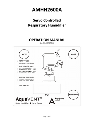
AMHH2600A Servo Controlled Respiratory Humidifier
OPERATION MANUAL (rev. 02 of 28/11/2012)
Page 1 of 18
CONTENTS PAGE
1.0 Introduction 1.1 Intended Use 1.1.2 Contraindications 1.2 Definitions
Page 03 03 03 03
2.0 Product Specifications 2.1 Transport and Storage 2.2 Statement on Environmental Management
04 05 05
3.0 Explanation of Controls and Indicators 3.1 Front panel 3.1.1 Display Window 3.1.2 Function Button 3.1.3 Mode 3.1.4 Patient Mode Indicator 3.1.5 Mute Button 3.1.6 Alarm Indicator 3.2 Right side panel 3.2.1 Heater Wire Power Socket 3.2.2 Temperature Probe socket 3.2.3 Mains Switch 3.3 Left side panel 3.3.1 Power Cord 3.3.2 Product Labelling 3.4 Electrical Rating 3.5 Safety Protection
06 06 07 07 09 10 12 12 13 14 14 14 14 14 14 15 15
4.0 Setting up the Humidifier
15
5.0 Operating the Humidifier 5.1 Basic Steps 5.2 Setting the Airway and Chamber Temperatures 5.2.1 Circuits with a Heater Wire 5.2.2 Circuits without a Heater Wire 5.3 Over-temperature Protection
15 15 16 16 17 17
6.0 Routine Maintenance 6.1 Cleaning 6.2 Maintenance 6.2.1 Calibration Check of Temperature Probes 6.2.2 Monthly Checks 6.2.3 Warranty
17 17 17 17 18 18
Page 2 of 18
1.0 INTRODUCTION 1.1 Intended use AMHH2600A Respiratory Humidifier is intended to be used to warm and humidify gases delivered to patients who require mechanical ventilation or other respiratory support via a tracheal tube or face mask. The clinical setting is in critical care units in hospitals. Gas is passed over the surface of heated water to add humidity and achieve a target gas temperature. Gas temperature can be maintained by a heater wire element contained within the tubing of the breathing circuit connected to the patient. Gas temperature is controlled accurately and measured via temperature probes located at the patient (proximal) end of the breathing circuit and at the humidification chamber outlet. The temperature of the gas at the patient-end of the breathing circuit is determined by the mode setting and displayed on the 4-digit LED display. AMHH2600A can be operated with or without a heater wire breathing circuit. 1.1.2 Contraindications There are no contraindications for use of the humidifier. Patient suitability for respiratory support using the humidifier is a medical decision, based on clinical or patient needs. 1.2 Definitions
NOTE: Symbols provide additional information which is intended to highlight procedures or conditions which may otherwise be misinterpreted or overlooked. CAUTION: A CAUTION symbol highlights the possibility of damage to the equipment if a procedure is not followed. WARNING: A WARNING symbol refers to conditions with a possibility of personal injury if a procedure is not followed.
Page 3 of 18
2.0 PRODUCT SPECIFICATIONS Dimensions: W135mm x D170mm x H156mm (without chamber) Weight: 2.9kg (without chamber) Electrical Rating: Supply Frequency: 50-60Hz Supply Voltage: 230V ± 23V Supply Current: 1.0A max at 230V Heater Plate Heater: 150w Heater Wire Capacity: 60W Gas Inlet Temperature Range: 18-26°C Temperature Control Heater Wire Circuit: Invasive mode airway T: 40°C / chamber T: 37°C Non –Invasive airway T: 34°C / chamber T: 31°C Non-Heater Wire Circuit: Invasive mode airway T: 37°C Non –Invasive airway T: 31°C Display: 4 digit 14 segment LED Range: 5.0 to 80.0°C; accuracy: ±0.5°C (at 25-40°C) Alarm Parameters: Heater Wire Circuit: High Airway Temperature Alarm: An immediate, audible alarm at a displayed gas temperature of 41°C or if the airway temperature exceeds 42°C Low Airway Temperature Alarm: An audible alarm between 10 minutes at 29.5°C and 60 minutes at 34.5°C High Humidity Alarm: An audible alarm if gas temperature exceeds 41°C Low Humidity Alarm: An audible alarm if the temperature is lower than 26°C over 10 minutes Non-Heater Wire Circuit: High Airway Temperature Alarm: An audible alarm if gas temperature exceeds 41°C Low Airway Temperature Alarm: An audible alarm if gas temperature descends to 29.5°C in invasive mode or to 26°C in non-invasive mode High Humidity Alarm: Light will ‘blink’, but no alarm will sound, if humidity gas temperature exceeds 66°C Low Humidity Alarm: An audible alarm if the temperature is lower than 26°C over 10 minutes Standards Compliance The humidifier is designed to conform to requirements of IEC 60601-1 and IEC 60601-1-2 Classified as: Class 1 Type B Drip Proof Continuous Operation Not to be used in the presence of flammable anaesthetic vapour General Information Fuses in this equipment should only be replaced with fuses of the correct type and rating as indicated on the appropriate labels or in the Technical Manual. A full technical description including circuit diagrams, parts list and service data is available. The safety, reliability and performance of this equipment are dependent upon: 1. The equipment being operated, maintained and repaired according to the instructions supplied 2. All servicing, calibration and repairs being carried out by a qualified service technician 3. Compliance with local electrical installation regulations Page 4 of 18
4. Maintenance of grounding integrity by connection to a "hospital grade" receptacle. Always disconnect supply before servicing 5. This product is intended for use by a qualified medical practitioner. Users should ensure that they are familiar with the use of the humidifier before connecting the device to a patient Further information please contact a Great Group Medical (GGM) distributor in your country, or contract GGM directly at: Great Group Medical Co., Ltd. No.81, Seconds 1, Guoguang Rd., Dali Dist, Taichung City 41262, Taiwan Tel. +886.4.2407.1449 ext 103 Fax.+886.4.2407.2796 [email protected] www.greatgroup.com.tw 2.1 Transport and Storage Transport Temperature: Storage Temperature:
minus 10 to 50°C (14 to 122°F) at 30 to 95% relative humidity minus 10 to 50°C (14 to 122°F) at 30 to 95 % relative humidity
2.2 Statement on Environmental Management GGM designs, manufactures and markets medical devices. These activities do not create a risk to the environment and therefore it is not viewed as requiring specific management. GGM is certified to ISO13485 and GMP. GGM does recognise the importance of addressing environmental issues. These are addressed in procedures or by Management Practice as appropriate. Routine audits are carried out as part of the QMS as required by ISO13485 – these also include examination of environmental issues, health and safety as well as Quality Management. The Company Secretary has been appointed to monitor the environmental impact of our activities and to take action to ensure that GGM’s activities impact minimally on the environment. Actions taken include: All clean cardboard and paper waste is collected for recycling A programme in place to improve energy efficiency through estates management Use of near home workers, where suitable, to minimise unnecessary travel Use of electronic data transmission and storage to minimise the use of paper where this is cost effective and available
Page 5 of 18
3.0 EXPLANATION OF CONTROLS AND INDICATORS 3.1 AMHH2600A Front Panel
Page 6 of 18
3.1.1. Display Window In normal working conditions, the LED displays the actual temperature of gas being delivered from the chamber or as measured at the patient-end of the breathing circuit. It automatically shows the lower of the 2 temperature measurements. Symbols:
A40.0
Airway temperature
A=40
Airway temperature set point
C37.0
Chamber temperature
C=37
Chamber temperature set point
H100
Heater plate temperature
ER.01
Error code
LOCK
Button is locked
UNL.K Button is unlocked
A.OPN
Airway temperature probe is faulty(open)
A.SHT
Airway temperature probe is faulty(short)
3.1.2. Function Button Locked / Unlock The system will automatically “Lock” the panel after 60 seconds when powered on and display the chamber temperature. Hold FUNCTION for 3 seconds = Unlock Hold FUNCTION for 3 seconds = Lock 【The system will re-lock automatically after 60 seconds, if there is no further panel operation】
Temperature Displays After powered on, the panel shows the lower temperature of either the Chamber or Airway Temperatures. Using FUNCTION you can view a variety of temperature settings, as below
C37.0
A.
UNL.K
C37.0
A40.0
C37.0
H 66
FUNCTION
FUNCTION
FUNCTION
FUNCTION
Hold 3Sec
Push
Push
Push
To display Airway Temperature, hold FUNCTION for 3 seconds + push FUNCTION once after 5 seconds. Page 7 of 18
Airway Temperature will switch back to the lowest temperature between Chamber and Airway Temperatures.
C37.0
UNL.K
C37.0
A40.0 After 5 Sec
B.
FUNCTION
FUNCTION
Hold 3Sec
Push 1 times
To maintain Airway Temperature on the display, hold FUNCTION for 3 seconds + push FUNCTION once + hold FUNCTION for 3 seconds
C37.0
UNL.K
C37.0
A40.0
LOCK
A40.0 Maintain
C.
FUNCTION
FUNCTION
FUNCTION
Hold 3Sec
Push 1 times
Hold 3Sec
To display Chamber Temperature, hold FUNCTION for 3 seconds + push FUNCTION once after 5 seconds. Chamber Temperature will switch back to the lowest temperature between Chamber and Airway Temperatures.
A36.0
UNL.K
A36.0
C37.0 After 5 Sec
D.
FUNCTION
FUNCTION
Hold 3Sec
Push 1 times
To maintain Chamber Temperature on the display, hold FUNCTION for 3 seconds + push FUNCTION once+ hold FUNCTION for 3 seconds.
A36.0
UNL.K
A36.0
C37.0
LOCK
C37.0 Maintain
E.
FUNCTION
FUNCTION
FUNCTION
Hold 3Sec
Push 1 times
Hold 3Sec
To display Heater Plate Temperature, hold FUNCTION for 3 seconds + push FUNCTION 3 times. Heater Plate temperature will display for 5 seconds and switch back to the lowest temperature between Chamber and Airway temperatures. Page 8 of 18
UNL.K
C37.0
FUNCTION
A40.0
FUNCTION Push 1 times
Hold 3Sec
F.
C37.0
C37.0
H 66
FUNCTION
FUNCTION
Push 1 times
Push 1 times
After 5 sce
To maintain on Heater Plate Temperature on the display, hold FUNCTION for 3 seconds + push FUNCTION 3 times + hold FUNCTION for 3 seconds.
C37.0
UNL.K
C37.0
A40.0
C37.0
H 66
LOCK
H 66 Maintain
G.
FUNCTION
FUNCTION
FUNCTION
FUNCTION
FUNCTION
Hold 3Sec
Push 1 times
Push 1 times
Push 1 times
Hold 3Sec
To return to Airway/Chamber/Heater Plate Temperatures
A40.0
A40.0
Maintain
OR
FUNCTION
UNL.K
OR
After 5 Sec
C37.0)
Hold 3 Sec
H 66
H 66
Maintain
【Attention】 Push the button, ‘beep’ x 1 sounding will be heard Hold button 3 seconds, ‘beep’ x 2 soundings will be heard 3.1.3. Mode
Heater Wire Mode When powered on, the system will automatically switch to “Heater Wire Mode”, when a breathing circuit equipped with a heater wire is used. The system will switch to “Non-Heater Wire Mode” after holding MODE for 3 seconds. 【Attention】 It is not possible to switch to “Non-Heater Wire Mode”, if a breathing circuit equipped with a heater wire Page 9 of 18
remains connected. The system will automatically switch to “Heater Wire Mode” when it connects with a heater wire again after turning off the heater wire. Patient Mode 1. The Patient Mode button will be locked after 60 seconds when powered on 2. Once powered on, the system defaults to “Invasive Mode” 3. Hold FUNCTIONfor 3 seconds + push MODE once and system will switch to “Non-Invasive Mode” 3.1.4. Patient Mode Indicator
【Invasive mode】default setting Heater Wire Mode: Airway T 40°C / Chamber 37°C Non-Heater Wire Mode: Airway T 37°C / Chamber T ≤66°C
【Non-Invasive mode】 Heater Wire Mode: Airway T 34°C / Chamber T 31°C Non-Heater Wire Mode: Airway T 31°C / Chamber T ≤66°C
【In Heater Wire Mode, the operation of changing Invasive Mode to Non-Invasive Mode】 Indicator Light
Display
Button
Description Current temperature of Chamber
Hold FUNCTION 3 seconds to unlock Current temperature of Chamber It is unlocked now Push MODE once and the system will switch to Non-Invasive mode Display will show Airway Temperature set point 34°C and remain for 1.5 seconds LED indicator will ‘blink’ 3 times Display will show Chamber Temperature set point 31°C and remain for 1.5 seconds
【In Heater Wire Mode, the operation of changing Non-Invasive Mode to Invasive Mode】 Indicator Light
Display
Button Page 10 of 18
Description
Current temperature of Chamber
Hold FUNCTION 3 seconds to unlock Current temperature of Chamber It is unlocked now Push MODE once and the system will switch to Non-Invasive mode Display will show Airway Temperature set point 40°C and remain for 1.5 seconds LED indicator will ‘blink’3 times Display will show Chamber Temperature set point 37°C and remain for 1.5 seconds
【In Non-Heater Wire Mode, the operation of changing Invasive Mode to Non-Invasive Mode】 Indicator Light
Display
Button
Description Current Airway Temperature
Hold FUNCTION 3 seconds to unlock Current Airway Temperature It is unlocked now Push MODE once and the system will switch to Non-Invasive mode Display will show Airway Temperature set point 31°C and remain for 1.5 seconds LED indicator will ‘blink’ 3 times Display will show Chamber Temperature set point <66°C and remain for 1.5 seconds
Page 11 of 18
【In Non-Heater Wire Mode, the operation of changing Non-Invasive Mode to Invasive Mode】 Indicator Light
Display
Button
Description Current Airway Temperature
Hold FUNCTION 3 seconds to unlock Current Airway Temperature It is unlocked now. Push MODE once and the system will switch to Non-Invasive mode Display will show Airway Temperature set point 37°C and remain for 1.5 seconds LED indicator will ‘blink’ 3 times Display will show Chamber Temperature set point <66°C and remain for 1.5 seconds
3.1.5. Mute Button
Pressing “Mute” will silence all alarms for 2 minutes. The alarm indicator will continue to flash until the cause of the alarm has been resolved. 3.1.6. Alarm Indicators 1. TEMPERATURE PROBE: <Alarm> When the temperature probe does not connect or is defective, the system will alarm with sound and continuous flashing LED 2. INSPIRATORY HEATER WIRE: <Alarm> When the inspiratory heater wire does not connect or is defective, the system will alarm with sound and continuous flashing LED 3. EXPIRATORY HEATER WIRE: <Alarm> When the expiratory wire heater wire does not connect or is defective, the system will alarm with 1 sound and continuous flashing LED 4. CHAMBER TEMPERATURE HIGH: <Alarm> When the Chamber Temperature is higher than 41°C, the system will alarm with sound 【Attention】 When in Non-Heater Wire Mode, the alarm will be inaudible but will ‘blink’ in yellow. alarm will sound if Chamber Temperature exceeds 66°C.
5.
AIRWAY TEMPERATURE HIGH <Alarm> Page 12 of 18
An
Heater wire on: When the Airway Temperature is higher than 42°C or when the display temperature is higher than 41°C Heater Wire off: When the Airway Temperature is higher than 41°C, the system will alarm with sound with continuous flashing LED 6.
CHAMBER TEMPERATURE LOW < Alarm> When the Chamber Temperature is lower than 26°C over 10 minutes, the system will alarm with sound and continuous flashing LED
7.
AIRWAY TEMPERATURE LOW < Alarm> Heater Wire Mode: Lower than 29.5°C over 10 minutes or lower than 34.5°C over 60 minutes in invasive mode, the system will have continuous flashing LED Non-Heater Wire Mode: Lower than 29.5°C and over 10 minutes in “Invasive Mode” , the system will alarm with sound and continuous flashing LED Lower than 26°C over 10 minutes in “Non-Invasive Mode”, the system will alarm with sound and continuous flashing LED
8.
SEE MANUAL <Alarm> When the red LED illuminates, a microprocessor fault has occurred and the system will no longer function. The system should be disconnected from the patient and the system serviced or repaired. Error Codes : ER.01: Heater wire is short-circuited ER.02: Heater wire fuse (F4) is open circuit ER.03: Thermal cut-out is open circuit
3.2 Right Side Panel
Page 13 of 18
3.2.1.
Heater Wire Power Socket The heater wire power connection plugs into this socket
3.2.2.
Temperature Probe Socket The temperature probe plugs into this socket
3.2.3.
Mains Switch Turns power to the humidifier on and off
3.3 Left Side Panel
3.3.1.
Power Cord Connect the humidifier to an AC power source as indicated on the side panel
3.3.2.
Product Labeling Product number Power supply Serial number
Page 14 of 18
3.4 Electrical Rating Supply Voltage: Supply Frequency:
AC 230V±23V or AC 115V±12V 50Hz/60Hz
3.5 Safety Protection Over-current protection : 115V/3A (fast burn type)/ 230V/1.5A (fast burn type) Over-heat protection: 115 ±3°C thermostat (manual reset type) 4.0
SETTING UP THE HUMIDIFIER 1. Select a suitable humidification chamber. Refer to the chamber instructions for use. Ensure that the chamber base and heater plate are undamaged; are clean and dry and no foreign objects are contained within the chamber 2. Slide the humidification chamber onto the heater plate. Push the chamber fully onto the plate. A guard will automatically lock the chamber in place 3. If using an auto-feed chamber, suspend a sterile water bag >1m above the humidifier and connect the chamber feed line to the water bag. If a line clamp is present, ensure that it is in the released position 4. Connect tubing from the gas supply to the inlet port of the chamber 5. Connect the inspiratory limb tubing of the circuit to the outlet port of the chamber 6. If using a heater wire circuit, connect the heater wire power connection(s) to the humidifier via the appropriate connecting cable 7. Insert the temperature probe sensors into the proximal and distal temperature probe ports on the breathing circuit. Push the temperature probe plug into the socket on the side of the humidifier. The humidifier is now ready to be powered on 8. To remove the chamber, push down on the guard. Pull the chamber forward until its rim is touching the guard. Remove fingers from the guard and pull the chamber away from the heater plate. Use this technique to avoid touching the hot heater plate or chamber base. Note that breathing circuits and humidification chambers should be replaced regularly in accordance with hospital infection control procedures and manufacturers’ instructions for use WARNING: When mounting a humidifier adjacent to a patient, ensure that the humidifier is always positioned lower than the patient DO NOT allow the chamber to be filled above the maximum fill level. Liquid could enter the breathing circuit if the chamber is allowed to overfill DO NOT fill the chamber with water in excess of 37°C Ensure that both temperature probe sensors are correctly and securely fitted. Failure to do so may result in temperatures in excess of 41°C being delivered to the patient
5.0 OPERATING THE HUMIDIFIER 5.1 Basic Steps 1. Plug the humidifier power cable into an AC supply of the voltage and maximum power rating specified on the side panel of the humidifier 2. Ensure that the humidification chamber and breathing circuit are installed and properly connected 3. Switch on the ventilator or gas supply. Perform flow and pressure testing applicable to the ventilator in use Page 15 of 18
4. Power on the humidifier using the power on/off switch at the side 5. The following information will then be displayed for a period of 1 second each: a. Company name “GGM” b. Model number eg. VH2600A c. Software version eg.V1.00 d. Set Airway Temperature (in °C) eg. A=40 e. Set Chamber Temperature) eg. C=37 6. If the display shows anything other than a temperature after the start-up sequence is completed, the unit should be removed from the patient for investigation 7. If a heater wire circuit is in use, ensure that the heater wire cable(s) is connected securely 8. At any time during use, if the gas flow is stopped or interrupted, the humidifier should be turned off WARNING: Unless the cause and effects of any alarm are understood and assessed to be of no hazard to the patient, the humidifier should be immediately powered off and disconnected from the patient The temperature delivered to the patient may exceed 41°C if the Airway Temperature probe is not inserted correctly at the patient-end of the inspiratory limb tubing Do not touch the heater plate as the surface temperature may exceed 85°C Other accessible metal surfaces may exceed 55°C Always ensure that the gas supply is flowing through the humidifier before connecting to the patient DO NOT use a heater wire breathing circuit in the presence of flammable anaesthetic vapour Monitor the water level in the chamber (or water bag for auto-feed feed chambers) and refill as necessary The liquid output of the humidifier may exceed 44mg.H2O/L flow if operating temperatures exceed 37°C at the chamber Electric shock hazard - do not disassemble the humidifier. In case of a fault or suspected fault, refer the system to a qualified service technician The power rating of the outlet socket on some ventilators may be less than the maximum required by the humidifier. The function of this humidifier may be adversely affected by the operation of high frequency surgical apparatus, shortwave or microwave equipment in the vicinity Some pressure regulated neonatal ventilators may cause the generation of high temperatures to reach the patient upon disconnection and reconnection of the inspiratory limb tubing, or disconnection only of the expiratory limb tubing. To prevent this occurring, it is recommended that the humidifier is powered off 5 minutes before disconnection of the tubing limb Keep the temperature probe outside an incubator or on top of patient bedclothes during use with neonates 5.2 Setting the Airway and Chamber Temperatures 5.2.1 Circuits with a Heater Wire Use of a heater wire circuit means that the humidifier employs 2 independent heating systems – (1.) the heater plate which heats the water (and therefore the gas exiting the chamber) and (2.) the heater wire itself. The heater wire maintains or increases the temperature of the gas as it travels along the tubing limb. The temperature of the gas leaving the chamber is regulated by the heater plate. The temperature at the chamber outlet is monitored by the first temperature probe. To see this temperature, refer to 3.1.2(c) above. In invasive mode, gas leaving the humidification chamber is 37°C and fully saturated. It is further heated by 3°C (by the heater wire) in the breathing circuit inspiratory limb tubing to reach 40°C at the proximal temperature port. It cools down in this unheated segment between the proximal temperature port and the patient’s lungs. Formation of water condensate is expected along this unheated section. Patients whose airways are by passed by a tracheal tube should receive inspiratory gases at core body Page 16 of 18
temperature 37°C and fully saturated (44mg.H2O/L of flow) in order to optimise mucociliary secretion transport. To achieve this, select “Invasive Mode”. As gas for inhalation passes the patient-end temperature port on the breathing circuit, it is expected that it will reduce to 37°C when delivered to the carina of the lungs. 5.2.2 Circuits without a Heater Wire The humidifier is set to HEATER WIRE as default when powered on It will switch to NON-HEATER WIRE Mode when holding ‘MODE’ for 3 seconds after powering on
N-H.W Hold 3 seconds, ‘beep’ x 2 sounds
Non-Heater Wire
In this mode, the temperature of the gas delivered to the patient is maintained by the heater plate only. This is controlled by the patient-end temperature probe. The temperature probe at the chamber outlet monitors and limits the temperature of the gas at this point to a maximum of 66°C. Gas leaves the humidification chamber at approximately 50°-65°C. It cools as it moves along the unheated inspiratory limb tubing. Water condensation will form. A water trap must be used to collect this condensate.
5.3 Over-temperature Protection If the heater plate temperature exceeds 115 ±3°C, power to the humidifier is discontinued by the activation of a thermostat. There will be no display or lighted indicators. On cooling, the overheat protector must be manually reset by opening the unit and depressing the red button found under the surface of the heater plate. This should only be carried out by Great Group Medical Co., Ltd or an authorised representative. 6.0 ROUTINE MAINTENANCE 6.1 Cleaning The humidifier must be powered off and the power cord disconnected from the power supply before cleaning Use only detergents and solutions indicated for use in cleaning surfaces of ventilators and similar equipment found in a critical care unit 6.2 Maintenance It is necessary to avoid contamination and wear of the humidifier by checking the system regularly. A review of maintenance requirement is advised once in every 12-month period. 6.2.1 Calibration Check of Temperature Probes Temperature probes should be checked once in every 12-month period to ensure that they are operating within manufacturer’s specifications. See below: The following procedure should be carried out by a hospital or servicing technician: 1. Use a calibrated mercury (Hg) thermometer 2. Place the thermometer and the patient (proximal) end of the probe into a container of water which is between 32°C and 40°C. 3. Turn the humidifier on. Allow the temperature of the probe and thermometer to stabilise. When stable, compare the temperature displayed on the display to the reading on the thermometer. The display should be within ± 0.5°C of the thermometer reading. If not, then it is recommended that the probe is replaced.
Page 17 of 18
6.2.2 Monthly Checks Check the temperature probe for damage to sensor tips, abrasion of the cable or damage to electrical contacts. Replace if necessary. Probes with gold plated electrical contacts may be ethylene oxide sterilised; other parts should be cleaned with a swab dipped in alcohol. The heater base may be cleaned by using cloth dampened with warm water. Check the heater wire cables for damage and replace as necessary. Insert the temperature probe and heater wire limb(s) assembly to the heater base. Power the humidifier ‘on’ and observe that the humidifier conducts the self test. Observe correct operation of self test. Check for correct display of ambient temperature and that no alarms are immediately activated. Ensure that the heater plate surface is clean and free from debris or abrasion. Routine maintenance will ensure continuous usage 6.2.3 Warranty The humidifier (excluding accessories) is warranted against manufacturing defects for a period not exceeding 2-years from the date of purchase of a previously unused unit. Accessories, such as temperature probes and heater wire cables are warranted for a period of 1 (one) year from the date of purchase. Specific warranty undertakings and exclusions are provided separately and are available upon request.
Great Group Medical Co., Ltd. No.168, Xingong 2nd Rd., Tianzhong Township, Changhua County, Taiwan Puh: +886.4.8758181; Faksi: +886.4.8756161 [email protected] www.greatgroup.com.tw
Page 18 of 18