Service Manual & Parts List
116 Pages
Preview
Page 1
Equipment for neonatal and premature infants: Infant Warmer
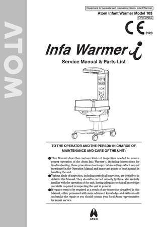
Atom Infant Warmer Model 103 ORIGINAL
0123
Service Manual & Parts List
TO THE OPERATOR AND THE PERSON IN CHARGE OF MAINTENANCE AND CARE OF THE UNIT: ●●This Manual describes various kinds of inspection needed to ensure proper operation of the Atom Infa Warmer i, including instructions for troubleshooting, those procedures to change certain settings which are not mentioned in the Operation Manual and important points to bear in mind in handling the unit. ●●Various kinds of inspection, including periodical inspection, are described in detail in this Manual. They should be carried out only by those who are fully familiar with the operation of the unit, having adequate technical knowledge and skills required in inspecting the unit in general. ●●If repairs seem to be required as a result of any inspection described in this Manual, either personnel with more advanced knowledge and skills should undertake the repair or you should contact your local Atom representative for repair service.
INTRODUCTION This Service Manual describes procedures for inspecting, repairing and changing the settings of the Infa Warmer i. It also describes precautions and troubleshooting in alarm conditions. The procedures described in this Service Manual should be carried out only by personnel trained in electricity and the operation of the unit. Neither Atom Medical Corporation nor its representative will be responsible for the quality and performance of the unit if the unit should not be handled as instructed or if unauthorized parts should be used in repairs. It should be noted that any responsibility arising from inspecting, repairing or changing the settings of the unit lies with the person who carried it out. Read this Service Manual carefully and familiarize yourself thoroughly with its contents before inspecting, repairing or changing the settings of the unit. Keep this Manual where it is readily accessible for reference when needed. For more detailed information on inspecting, repairing and changing the settings of the unit, contact your local Atom representative. Read the Operation Manual thoroughly before using the Service Manual.
SAFETY INFORMATION Please read the Manual carefully before operating the unit. Please follow the instructions when operating the unit.
Basic Instructions 1. Medical institutions are responsible for the maintenance, inspection and care of the unit. 2. When you choose to have the unit maintained and inspected or when the unit is found to be in need of repairs from the results of inspection, consult your local Atom representative and take one of the following measures. 1) Ask someone who has completed a training course specified by Atom and who has sufficient technical knowledge and skills to do the work. 2) Ask Atom to send its service engineer if a person who has completed a training course specified by Atom and who has sufficient technical knowledge and skills is not available. 3) Ask Atom for its approval of returning the unit for repair service. 3. Follow the instructions for safety. Read the operating precautions thoroughly before operating the unit. 4. Inspect the unit on a periodical basis. Periodical inspection is needed to use the unit in the optimum condition. 5. Ensure that the unit will not be used if it is found to be defective. Take proper measures to ensure that a defective unit will not be used by mistake before it is properly inspected, repaired and has its settings changed for normal operation. Such measures include indicating on the unit that it is under inspection/ repair and keeping it away from other devices that function correctly.
1
Definition of Warning Indication Three levels of warning indication are used throughout this Service Manual & Parts List and on the unit. They are defined as follows. A DANGER notice indicates an immediately hazardous situation which, if not avoided, DANGER: will result in death or serious injury, serious damage to property such as total loss of use of equipment, or fire. A WARNING notice indicates an indirectly (potentially) hazardous situation which, WARNING: if not avoided, will result in death or serious injury, serous damage to property such as total loss of use of equipment, or fire. A CAUTION notice indicates a hazardous situation which, if not avoided, can result in CAUTION: minor or moderate injury, partial damage to equipment, and loss of data stored in computers.
Definition of Symbols 1. Symbols to indicate danger, warning or caution Symbol Title and indication General attention Indicates unspecified general danger, warning, or caution. Caution: Hot surface Indicates that the surface can be dangerously hot under certain conditions.
2. Symbols to prohibit action Symbol
Title and indication
General prohibition Indicates unspecified general prohibition. Prohibition of use of fire Indicates prohibition of use of fire where an external use of fire may cause the unit to ignite under certain conditions. 3. Symbols to give instructions for action Symbol
Title and indication
General instruction Indicates unspecified general action on the part of the user. Connect a ground wire Instructs the user to connect the ground wire without fail where the unit is provided with a ground terminal.
2
4. Symbols of international standards (IEC) Symbol
Title and indication
Equipment partially on Indicates that a part of the device is “ON.” Equipment partially off Indicates that a part of the device is “OFF.” Type BF applied part Indicates that the device is classified as Type BF in terms of the degree of protection against an electric shock. Bell silenced Indicates either a control switch to silence the bell permanently or temporarily or that the bell is silenced. Caution Indicates that the user needs to see a relevant accompanying document before operating the unit.. Caution against electrostatic discharge Indicates that appropriate precautions must be taken against electrostatic discharge. Lighting Indicates a switch that controls lighting. Recycle mark (battery) Indicates that recycling is recommended. Date of manufacture Indicates the date when the unit was manufactured in the factory. WEEE symbol In the EC area, an electrical and electronic product falling in one of the categories specified by “DIRECTIVE 2002/96/EC OF THE EUROPEAN PARLIAMENT AND OF THE COUNCIL of 27 January 2003 on Waste Electrical and Electronic Equipment (WEEE)” should be disposed of in a manner consistent with relevant laws and regulations. This symbol indicates that the above-mentioned requirement applies to this product. 5. Other symbols Symbol
Title and indication
Setting Indicates that a setting is increased. Setting Indicates that a setting is decreased. Alarm Indicates a power failure alarm.
3
Symbol
Title and indication AC power Indicates that the device is connected to AC power. Battery Indicates that the unit is being powered by the Power Pack i (UPS). Alarm Indicates that a system of the unit is in an abnormal condition. Alarm 1. In manual control (when monitoring the skin temperature): Indicates that the skin temperature has become 40°C or higher. 2. In servo control: Indicates that the skin temperature deviates from the set temperature by 1.0°C or by 0.5°C. Alarm Indicates that a wire of the skin temperature probe has snapped or short-circuited. Alarm Indicates that 15 minutes have elapsed since the heater was turned on. Alarm Indicates that the canopy is tilted. Setting Indicates a setting of the skin temperature. Skin temperature Indicates a detected current skin temperature of the infant. Heater Indicates the manual control mode, the manual control mode switch and the heater output. Skin temperature Indicates the servo control mode, the servo control mode switch and the skin temperature probe connecting port. Preheat Indicates the preheat mode and the preheat mode switch. Peripheral temperature Indicates the function related to the infant’s peripheral temperature (skin temperature 2). Temperature unit Indicates the switch to select either °C or °F as the unit of the temperature to be displayed. Timer Indicates the timer.
4
Symbol
Title and indication Timer Indicates the timer switch. SpO2 Indicates the alarm limit selector switch.
SpO2 Indicates the sensitivity selector switch. (Masimo) SpO2 Indicates the patient cable connecting port. SpO2 Indicates that the SpO2 lower alarm limit is set to lower than 85%. SpO2 (Masimo) Indicates that the current sensitivity is “APOD.” SpO2 (Masimo) Indicates that the current sensitivity is “NORM.” SpO2 (Masimo) Indicates that the current sensitivity is “MAX.” SpO2 Indicates a detected current SpO2 value. Pulse rate Indicates a detected pulse rate.
(Nellcor)
(Nellcor)
(Nellcor)
(Nellcor)
SpO2 Indicates that the SatSeconds limit is set. Also indicates that the SatSeconds point is increasing or decreasing. SpO2 Alarm Indicates an interference alarm. SpO2 Alarm Indicates a pulse search alarm or a pulse timeout alarm. SpO2 Alarm Indicates a sensor off alarm. Load capacity Indicates the maximum load capacity.
5
Symbol
Title and indication Prohibition of lubrication Indicates that lubrication is prohibited. Avoid getting caught Indicates that the user must avoid getting caught in the gap in the device.
General Precautions
DANGER To prevent a hazardous explosion, do not handle the unit where oxygen, nitrous oxide or a flammable anesthetic gas is used.
WARNING Do not touch the unit with a wet hand. Connect the power cord of the unit only to a power outlet including a ground terminal and meeting the rated electrical requirements of the unit. If a fingertip or a tool should touch a harness or a terminal in the unit, an electric shock or a short circuit may result. Be sure to disconnect the power cord before handling the unit.
CAUTION Only qualified personnel belonging to Atom or a qualified service person properly trained in the handling of the unit should inspect, repair, change the settings of, or disasseble and assemble the unit. When replacing a part, make sure that the new part you intend to use is the one specified by Atom. Using a part that is not specified by Atom may compromise the sefety feature or the unit. Do not handle the unit in an electromagnetic environment where electrocautery or imaging devices such as MRI and CT equipment are used, or near equipment provided with an electromotor that consumes a lot of currents. The electronics of the unit may be affected by the radiation of various kinds of electromagnetic waves in the hospital and be led to malfunction. Do not disinfect the unit by immersing it in a medical fluid, autoclaving or with EOG. Follow the instructions of the Operation Manual in cleaning and disinfection. Do not immerse the unit in a medical fluid. A portion of the medical fluid may enter the unit and short the electronic cuicuits inside. After repairing, disassembling and assembling, changing the settings of, or cleaning and disinfecting the unit, check that the unit operates properly.
6
CONTENTS INTRODUCTION... 1 PLEASE READ WITHOUT FAIL [1]
[2]
1-1.
DANGER... 10
1-2.
WARNING... 11
1-3.
CAUTION... 13
Parts Identification... 15 Main Body... 15 Support Column... 16 Operation Panel... 17
MAINTENANCE Inspection before Use... 21 Quarterly Inspection... 23 Inspection Checklist... 24 Periodical Replacement Parts... 25 Main Body... 26 Others... 27
Troubleshooting... 28 5-1. 5-2. 5-3.
Alarms... 28 Troubleshooting... 32 Troubleshooting Flowchart... 33 5-3-1. Canopy... 34 5-3-2. SpO2... 37 5-3-3. Power Unit... 44 5-3-4. Mattress Platform... 50 5-3-5. Base... 54
DISASSEMBY AND REPLACEMENT [6]
Disassembly and Replacement Procedures... 56 6-1.
Canopy... 56 6-1-1. Replacing the Upper Covers of the Canopy... 56 6-1-2. Replacing the Lower Covers of the Canopy... 57 6-1-3. Replacing the Heater Module.. 57 6-1-4. Replacing the Heater... 58 6-1-5. Replacing the Microswitch... 59 6-1-6. Replacing the LED Lighting Unit... 60
Replacing the Lighting Lamp Cover... 60 Support Column... 61 6-2-1. Replacing the Rear Cover of the Support Column... 61 6-2-2. Replacing the Front Cover of the Support Column... 61 6-2-3. Replacing the Pulse Oximeter Board... 61 6-2-4. Replacing the Insulating Substrate... 62 6-2-5. Replacing the Relay Board... 63 6-2-6. Replacing the Skin Temperature Probe Board... 63 Power Unit... 64 6-3-1. Replacing the Light Control Knob... 64 Replacing the Power Switch... 65 Replacing the Light Control Switch... 65 6-3-4. Replacing the Speaker... 65 6-3-5. Replacing he Triac Board... 66 6-3-6. Replacing the Power Transformer... 66 6-3-7. Replacing the Battery for Power Failure Alarm... 67 6-3-8. Replacing the Fuse for the Main Board... 68 6-3-9. Replacing the Main Board... 68 6-3-10. Replacing the LED Board... 68 6-3-11. Replacing the Upper/ Lower Operation Panel Sheets... 69 6-3-12. Replacing the Cable for Power Supply Part... 69 6-3-13. Replacing the Cable for Lighting Lamp/Tilting Knob... 69 6-3-14. Replacing the Cable for Relay Board . ... 70 6-3-15. Replacing the Cable for Skin Temperature Probe Board ... 70 6-3-16. Replacing the Connector Cap... 70 Table Unit... 71 6-4-1. Replacing the Front Baby Guard/Side Baby Guard... 71 6-4-2. Replacing the Rear Baby Guard... 72 6-3-2. 6-3-3.
Cleaning and Disinfection... 26 4-1. 4-2.
[5]
6-3.
Maintenance Inspection... 20 3-1. 3-2. 3-3. 3-4.
[4]
6-2.
Operating Precautions... 10
2-1. 2-2. 2-3.
[3]
6-1-7.
6-4.
[7]
Block Diagram... 87
[9]
Wiring Diagram... 88
[10] Parts List... 89 10-1. Fig.1 Overall View and Accessories... 90 10-2. Fig.2 Canopy... 92 10-3. Fig.3 Support Column... 94 10-4. Fig.4 Power Unit... 96 10-5. Fig.5 Mattress Platform... 98 10-6. Fig.6 Main Body and Base... 100
Appendix [11] Technical Information... 102 11-1. Principle of Operation... 102 11-1-1. Description of the Principle of Operation... 102 11-1-2. Illustration of the Principle of Operation... 103 11-2. Technical Data... 104 11-3. EMC Level and Classification... 108
[12] Disposal... 112
INFORMATION
INFORMATION
[8]
DISASSEMBY AND REPLACEMENT
6-6.
7-9.
Setting the Fast Response (Nellcor only)... 86 Switching between the CPR/Apgar Modes... 86
MAINTENANCE
6-5.
7-8.
PLEASE READ WITHOUT FAIL
Replacing the Pivot Shaft... 72 Replacing the Cushioning Material... 72 6-4-5. Replacing the Rotary Damper... 73 6-4-6. Replacing the Mattress Platform... 74 6-4-7. Replacing the Corner Cover... 74 6-4-8. Replacing the Wire for Tilting Unit... 74 6-4-9. Replacing the Tilting Unit (for Mattress Platform)... 75 Main Body... 75 6-5-1. Replacing the Hi-Low Drive Board for Hi-Low Stand... 76 6-5-2. Replacing the Fuse for the Hi-Low Drive Board for Hi-Low Stand (for the Primary Side/Secondary Side)... 77 6-5-3. Replacing the Power Transformer... 77 6-5-4. Replacing the Breaker... 78 6-5-5. Replacing the AC Inlet... 78 6-5-6. Replacing the Cord Cleat... 79 6-5-7. Replacing the Connector Cap for Power Pack i... 79 Base... 79 6-6-1. Replacing the Caster... 79 6-6-2. Replacing the Relay Board for Hi-Low Pedal... 80 6-6-3. Replacing the Foot Switch... 80 6-6-4. Replacing the Hi-Low Stand Actuator... 80 6-4-3. 6-4-4.
Settings... 82
7-5. 7-6. 7-7.
List of Setting Items... 82 Enabling/ Disabling the Key Click... 83 Adjusting the Alarm Volume... 83 Changing the Temperature Deviation Limit of the Set Temperature Alarm... 84 Changing the Averaging Time (Masimo only)... 84 Changing the Synclonizing Pulse Beep Volume... 85 SatSeconds (Nellcor only)... 85
APPENDIX
7-1. 7-2. 7-3. 7-4.
Operating Precautions
[1] Operating Precautions Please follow the operating instructions described in this Service Manual & Parts List for the safe use of the unit. The unit should be operated only by those who have been trained and instructed properly in its operation under the supervision of qualified medical personnel familiar with the currently known risks and benefits associated with the use of a radiant warmer. The unit should be operated only for its intended use.
1-1.
DANGER
Death or serious injury, damage to equipment or a fire will result if the instructions given below are not followed. Monitor the infant’s skin temperature when operating the unit. The operator must monitor the infant’s skin temperature when operating the unit. Avoid unattended use of the unit. Do not leave the unit unattended with the baby guards folded down. If the baby guards are left folded down, the infant may fall out and get fatally injured. Never leave the unit unattended with the baby guards folded down. Do not tilt the mattress platform with the baby guards folded down. If the mattress platform is tilted with the baby guards folded down, the infant may fall out. When you pull up and lock the baby guards in position, be sure to check that no mattress sheet or linen is caught between any of the baby guards and the mattress platform. Make sure that the baby guards are locked securely. If linen or other object is caught between any of the baby guards and the mattress platform, remove it. Otherwise, the baby guards will not be locked completely. The baby guards may swing down and the infant may fall out of the unit and suffer serious or fatal injury. Stop using the unit immediately and seek repair if the locking mechanism of the baby guards or other related parts should be found faulty in any way. The infant may fall out. Never place a body warmer or any other possible ignition source in or near the unit. Use of oxygen will increase the risk of explosion or fire. Body warmers or other devices in which fire is used or which will generate a spark may cause an explosion or a fire if used near the unit. Do not use the unit in the presence of a flammable anesthetic gas. The unit may cause an explosion or a fire if used in the presence of such a gas. Do not use ether, alcohol or any other ignitable substance. Even a small amount of ether, alcohol or any other ignitable substance may cause a fire when mixed with the oxygen supplied to the unit. Do not hang any flammable materials on the canopy. It may cause a fire.
10
Operating Precautions
PLEASE READ WITHOUT FAIL
Ground the unit securely. Otherwise, a leakage current may cause an electric shock. In order to complete the ground connection, connect the power cord only to a properly grounded 3P power outlet including a ground terminal. Do not operate the unit if you have any doubt about its ground connection. Do not use a device generating high frequency near the unit. To prevent malfunction of the unit due to jamming, do not use electric surgical knives, portable and mobile communication equipment and other devices which generate high frequency near the unit during its operation. Analyze arterial gas levels repeatedly when a high oxygen environment is required. When the infant requires a high oxygen environment, it is extremely important and essential to periodically analyze arterial gas levels. Follow the doctor’s instructions in measuring the oxygen concentration because ignoring essential requirements may increase the risk of retinopathy of prematurity and other adverse effects. Do not give a shock to the unit or let it hit anything. The screws or fixed parts may become loose. If the unit is to be used beyond its expected life span, overall repairs including replacement of parts must be carried out.
1-2.
WARNING
Death or serious injury due to a fire or an electric shock will result if the instructions given below are not followed. Be sure to follow the doctor’s instructions in setting the infant’s skin temperature. Be sure to follow the doctor’s instructions in supplying oxygen. Use only oxygen for medical use. Be sure to bear in mind the following precautions during oxygen supply. • Do not place a body warmer, a flashlight, oils and fats, or flammable vaporizable matters near the unit. • Use pure cotton for the infant’s clothing, bed sheets, etc. Do not use any material that is easily charged with static electricity. • Use pure cotton or fire-proof materials for the clothing of doctors, nurses and ambulance staff who handle this unit. Bear in mind the following precautions while using oxygen supply equipment. • If oil, grease or a grease-like substance should get in contact with pressurized oxygen, a violent spontaneous ignition may occur. Do not let such substances stick to the oxygen pressure regulator, the oxygen cylinder valve, piping, connections and other parts of oxygen supply equipment. • On a high-pressure oxygen cylinder, use only a tested pressure reducing valve or pressure regulating valve indicated specifically for oxygen supply. Do not use such a valve for any gas other than air or oxygen. It is dangerous to use a valve to supply a gas other than air or oxygen and then to supply oxygen again.
11
Operating Precautions
Smoking is prohibited in the room where the unit is installed. Do not place any possible ignition sources in the room. Avoid damaging the power cord. A damaged power cord may cause a fire or an electric shock. • Do not get the power cord caught between the unit and the wall, a shelf or the floor. • Do not place the power cord near a heating apparatus or heat it. • Do not put anything heavy on the power cord. • Always grasp the power plug with your hand to remove the power cord from the power outlet. A damaged power cord should be replaced immediately with a new one. Use only the power cord supplied with the unit. Otherwise, a fire or an electric shock may result. Do not touch the heater with your hand when the heater is on. You may burn yourself. Do not touch the power plug with a wet hand. Touching the power plug with a wet hand may cause an electric shock. Do not disassemble or modify the unit. Disassembling or modifying the unit may cause a fire, an electric shock or injury. Do not install the unit where it will be exposed to excessive humidity, dust or steam. Installing the unit in such a place may cause a fire or an electric shock. Before cleaning and disinfecting the unit, be sure to turn the power switch off, remove the power plug, and allow the heater temperature to drop sufficiently. The power outlet should be located near the unit to prevent accidental contact with a trailing power cord. Use a separate power outlet for each unit. Do not put many loads on one power outlet. In order to complete the ground connection, connect the power cord only to a properly grounded 3P power outlet including a ground terminal. Do not operate the unit if you have any doubt about its ground connection. Ground peripheral electric equipment securely. Never connect the unit to a power outlet other than that specified. The unit should be serviced only by qualified personnel. Be sure to inspect the unit at the start of each day. Operating the unit without inspecting it before at the start of each day may let a defect pass unnoticed and cause a potentially unfavorable outcome.
12
Operating Precautions
1-3.
PLEASE READ WITHOUT FAIL
Check for conformity to the applicable standard if the unit is going to be connected to another medical device for use as a system. Accessory equipment connected to the analogue and digital interfaces must comply with the relevant IEC standards (e.g. IEC 60950 for data processing equipment). Furthermore all configurations should comply with IEC 60601-1-1. But the items that are not specified as part of the system should not be connected. Anybody who connects additional equipment to the signal input or signal output configures a medical system, and therefore should make the medical system comply with the requirements of IEC 60601-1-1 on his or her own responsibility. If in doubt, consult your local Atom representative.
CAUTION
Injury or damage to surrounding objects may result if the instructions given below are not followed. Be sure to clean and disinfect the unit before using it for the first time after purchase. The unit is shipped without being disinfected. During the standby mode, be sure to preheat the unit in order to keep the mattress surface temperature stable. Place the infant on the mattress only after the mattress surface temperature has stabilized. Do not twist or pull the cords by force. If any defect should be found, ask an expert for repair without attempting to repair it yourself. When feeding the cords and tubes into the unit, be very careful not to let them wind or tighten around the patient. Remove the power plug from the power outlet before moving the unit to another place or when the unit is not going to be used for a long time. Moving the unit to another place with the power plug connected to the power outlet will damage the power cord and may cause a fire or an electric shock. Remove the power plug from the power outlet before cleaning and disinfecting the unit. Cleaning and disinfecting the unit with the power plug connected to the power outlet may cause an electric shock. Install the unit on a stable surface. Installing the unit on an unstable platform or a tilted surface will cause it to fall or drop and may injure someone. Therefore, before installing the unit, make sure that the place where the unit is to be installed is stable and strong enough to support the weight of the unit. Install the unit out of reach of small children. Do not operate the unit with the canopy covered with a cloth, etc. Operating the unit covered with a cloth or pressed tightly against the wall may cause a fire or an electric shock due to overheating. Do not install the unit in direct sunlight or near a heating apparatus.
13
Operating Precautions
Do not expose the unit to extraordinarily high temperature or excessive humidity. Do not place anything heavy on the unit. Do not let the unit hit anything, fall, or drop inadvertently. Do not attach any peripheral device that is not specified by Atom to the unit. Check the operation of the peripheral devices. If a device transmitting or receiving weak signals is installed near the unit, it may be affected by the electromagnetic waves generated by the latter. Check the operation of the peripheral devices for any effect before using the unit in clinical settings. Stop using the unit immediately if any trouble is detected. Be sure to cover the mattress with a mattress sheet. The mattress is not breathable and may cause a bedsore.
14
Parts Identification
2-1.
PLEASE READ WITHOUT FAIL
[2] Parts Identification Main Body ① ⑭ ⑬ ⑫
②
⑪
⑩✽
⑮
⑨
③ ④
⑯
⑧ ⑦
5A
BREAKER
5A
⑰ UPS
230V~ 50/60Hz
⑤
⑤
⑱
⑥
No. ① ② ③ ④ ⑤ ⑥ ⑦ ⑧ ⑨
Name Canopy Lighting lamp Mattress Baby guard Foot switch Caster Mattress platform tilting lever Mattress platform Tube introduction slit packing
No. ⑩* ⑪ ⑫ ⑬ ⑭ ⑮ ⑯ ⑰ ⑱
Name Resuscitator Operation panel Alarm lamp Heater Canopy fixing screw I/O port (communication connector) Breaker Connector for the Power Pack i (UPS) AC inlet
* The figure shows the unit in which the Resuscitation Unit (P type, E type) or the Blender Unit (P type, E
type) is installed. For information on the Resuscitation Unit (P type, E type) or the Blender Unit (P type, E type), see the Service Manual of the Unit concerned.
15
Parts Identification
2-2.
Support Column
①
②✽
③ ④ ⑤ No. ① ②* ③ ④ ⑤
Name Operation panel Resuscitator Skin temperature connecting port 1 Skin temperature connecting port 2 SpO2 connector jack
* The figure shows the unit in which the Resuscitation Unit (P type, E type) or the Blender Unit (P type, E type) is installed. For information on the Resuscitation Unit (P type, E type) or the Blender Unit (P type, E type), see the Service Manual of the Unit concerned.
16
Parts Identification
Operation Panel
PLEASE READ WITHOUT FAIL
2-3.
Alarm
Temperature
Timer
Pulse oximeter
Others (Masimo)
(Nellcor)
Alarm Symbol
Function External alarm indicator Comes on when a high priority alarm occurs, except for a power failure alarm. Mains on indicator Comes on when the power cord is connected to the AC power source. Battery operation indicator Comes on when the optional Power Pack i (UPS: option) is being used as a power source. Power failure alarm indicator Comes on when the power cord gets disconnected from the AC power source while the unit is in operation or in the event of power failure. System failure alarm indicator Flashes when a system error or some other trouble is detected. Alarm silence indicator Comes on when an audible alarm is silenced.
Symbol
Function Set temperature alarm indicator Comes on when a displayed skin temperature deviates from the set temperature by more than 1ºC (or 0.5ºC alternatively) in the servo control mode. Flashes when skin temperature 1 exceeds 40ºC in the manual control mode. Skin temperature probe alarm indicator Flashes when a wire of the skin temperature probe has snapped or short-circuited in the servo control mode. Comes on when it has snapped or short-circuited in the manual control mode. Baby check alarm indicator Comes on in 15 minutes when the heater output is set to 35% or higher. Can be reset by pressing the alarm silence/reset switch but comes on again in another 15 minutes. Canopy tilt alarm indicator Comes on when the canopy is tilted.
17
Parts Identification
Temperature
Timer
Symbol
Symbol
Function Operation mode indicator (servo control mode) The servo control mode indicator is on in servo control operation. (It flashes when the skin temperature is being set.) Operation mode indicator (manual control mode) The manual control mode indicator is on in manual control operation. (It flashes when the heater output is being set.) Preheat indicator Comes on when the preheating function is on (only in the manual control mode). Heater output indicator Indicates the heater output level (1~100%) with a bar graph. Skin temperature display 1) Displays the infant’s skin temperature detected by the skin temperature 1 probe. 2) Displays the infant’s skin temperature detected by the skin temperature 2 probe while the skin temperature 2 selector switch is being pressed. Setting display 1) Displays a set skin temperature in servo control operation. In this case, the “ ºC ” indicator on the upper right of the display is on. (The display flashes when the skin temperature is being set.) 2) Displays the heater output in manual control operation. In this case, the “ % ” indicator on the lower right of the display is on. 3) Displays “ ” in preheating. Switch Servo control mode switch Press this switch to select servo control operation. Manual control mode switch Press this switch to select manual control operation. Preheat switch Press this switch in the manual control mode to start preheating. Skin temperature 2 selector switch While this switch is being pressed, the infant’s skin temperature detected by the skin temperature 2 probe is displayed on the skin temperature display. ºC/ºF selector switch Press and hold this switch for one second to toggle between ºC and ºF.
18
Function Timer display Displays up to 60 minutes 00 seconds. Second counter Counts up 6 seconds twice every 30 seconds. The lamps come on one by one from 0 to 6, indicating 0, 1, 2...6 seconds. Switch Timer switch Press this switch to start/reset the timer.
Pulse oximeter Symbol
Function SpO2 display Displays a detected SpO2. If an SpO2 sensor is not connected or if an SpO2 sensor is not attached properly to the infant, it will be indicated on this display. When the SpO2 upper alarm limit or the SpO2 lower alarm limit is being set, the selected setting is displayed here. If the SpO2 lower alarm limit should be set lower than 85%, the “<85%” indicator on the upper left of the display will come on. Pulse rate display Displays a detected pulse rate. If an SpO2 sensor is not connected or if an SpO2 is not attached properly to the infant, it will be indicated on this display. When the pulse rate upper alarm limit or the pulse rate lower alarm limit is being set, the selected setting is displayed here. SIQ bar graph Indicates the timing of pulses and the quality of input signals. The bar rises and falls in time with a pulse. The height of each bar is in proportion to the quality of the input signal concerned. The more reliable a measured value is, the higher the bar becomes. The less reliable a measured value is, the (Masimo) lower the bar becomes. Blip bar Rises and falls in time with a pulse.
(Nellcor)
Parts Identification
Others
Symbol
Symbol
(Masimo) (Masimo) (Masimo) (Masimo)
(Nellcor)
(Nellcor)
(Nellcor)
(Nellcor)
Function Alarm limit selector switch Press this switch to select one of the four alarms: the SpO2 upper limit alarm, the SpO2 lower limit alarm, the pulse rate upper limit alarm and the pulse rate lower limit alarm. When either the SpO2 upper limit alarm or the SpO2 lower limit alarm is selected, “ ” or “ ” on the left of the SpO2 display flashes. When either the pulse rate upper limit alarm or the pulse rate lower limit alarm is selected, “ ” or “ ” on the left of the pulse rate display flashes. Sensitivity selector switch Press this switch to set the sensitivity to a low (“APOD”), normal (“NORM”), or high (“MAX”) level. (APOD) sensitivity indicator Comes on when the current sensitivity is “APOD.” (NORM) sensitivity indicator Comes on when the current sensitivity is “NORM.” (MAX) sensitivity indicator Comes on when the current sensitivity is “MAX.” SatSeconds indicator Comes on when the SatSeconds limit is set. Flashes when counting up or counting down. Interference alarm indicator Comes on or flashes when interference is detected. Pulse search alarm indicator Comes on when no pulse is detected. Flashes if it becomes impossible to detect a pulse during SpO2 measurement. Sensor off alarm indicator Flashes if the sensor attached to the patient has come off. Also flashes if the patient cable or the sensor was come off the unit. Comes on when the SpO2 lower alarm limit is set to lower than 85%.
PLEASE READ WITHOUT FAIL
Pulse oximeter
Function Setting up/down switch Press this switch to set the skin temperature, the heater output, and the upper/lower alarm limits to a desired level. To set the skin temperature, press the servo control mode switch and then this switch. To set the heater output, press the manual control mode switch and then this switch. To set a upper or lower alarm limit, press the alarm limit selector switch to select the SpO2 upper limit alarm, the SpO2 lower limit alarm, the pulse rate upper limit alarm or the pulse rate lower limit alarm, and then press this switch. Alarm silence/reset switch Press this switch to silence or reset an audible alarm. Power switch Press this switch to turn the power on or off. You can turn on the lighting lamp and adjust the height of the Hi-Low stand even when the power switch is off. Light control switch Controls the intensity of lighting.
19
Maintenance Inspection
[3] Maintenance Inspection In order to use the unit safely for a longer period, perform the maintenance inspections described below.
CAUTION Medical institutions are responsible for performing the maintenance inspections. They are allowed to entrust the maintenance inspections of the unit to an appropriate external contractor. Clean and disinfect the unit and its accessories before maintenance inspections, repairs, or disposal.
• Inspection before use Check the basic functional operation of each part of the unit every time you are going to use the unit. • Quarterly inspection Check the operation of each function of the unit every three months. • Periodical inspection Periodical inspection needs to be performed annually. Contact your local Atom representative for periodical inspection. • Parts requiring periodical replacement Some parts need to be replaced periodically depending on their period of use.
20