Service Manual
88 Pages
Preview
Page 1
0 - 12
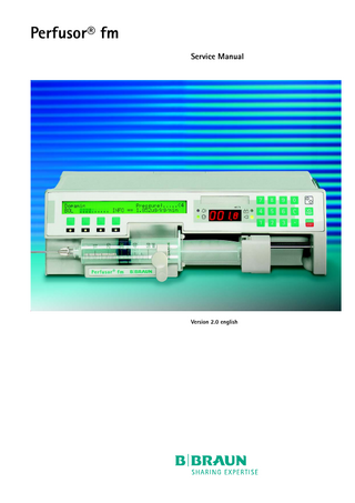
Perfusor® fm Service Manual
Version 2.0 english
0-
2.0, 27.04.06
0
This Service Manual is valid for
Voltages 200 V to 240 V: Order - No. Perfusor® fm, German... 871 5823 Perfusor® fm, French... 871 5920 Perfusor® fm, Dutch... 871 5939 Perfusor® fm, Italian... 871 5963 Perfusor® fm, Danish... 871 5831 Perfusor® fm, Norwegian... 871 5840 Perfusor® fm, Swedish... 871 5858 Perfusor® fm, Finnish... 871 5866 Perfusor® fm, Spanish... 871 5874 Perfusor® fm, Portuguese... 871 5882 Perfusor® fm, English (BSI)... 871 5890 Perfusor® fm, English... 871 5904 Perfusor® fm, Turkish... 871 5912 Perfusor® fm, Czech... 871 5947 Perfusor® fm, Polish... 871 5955 Voltages 100 V to 120 V: Perfusor® fm, English (BSI)... 871 5815 Perfusor® fm, Dutch... 871 5971 Perfusor® fm, Spanish... 871 5980 Perfusor® fm, Kastelanisch... 871 5998
This Service Manual is available under the following part number:
Designation Part No. Service Manual Perfusor® fm, english... 8713 9117
Languages of this Manual
Designation Part No. Service Manual Perfusor® fm, german... 8713 9116
The complete Service Manual contains the following pages:
Page 0-1 to page 0-10 Page 1-1 to page 1-8 Page 2-1 to page 2-14 Page 3-1 to page 3-16 Page 4-1 to page 4-20 Page 5-1 to page 5-2 Page 6-1 to page 6-2 Page 7-1 to page 7-2 Page 8-1 to page 8-4 Page 9-1 to page 9-2 Page 10-1 to page 10-4 Page A-1 to page A-2
0- 2
Perfusor® fm, 2.0 gb
2.0, 27.04.06
0-
Table of Contents
0
Important Preliminary Remarks
Service Work Technical Safety Checks Current Versions Revision Service Responsibility of the Manufacturer Quality Management Checks and Repair Notes on ESD Spare Parts and Test Equipment Setting Off List of Abbreviations
Page Page Page Page Page Page Page Page Page Page Page
0-5 0-5 0-5 0-5 0-6 0-6 0-6 0-6 0-7 0-7 0-8
Contact Persons
Technical Training Entry for Technical Training Ordering of Spare Parts and Test Equipment Service Hotline Return of Spare Parts and Test Equipment Safety Officer (§ 30 MPG) Translation
Page Page Page Page Page
0-9 0-9 0-9 0-9 0-9
Page Page
0-9 0-9
System Overview
Physical Construction Operation Flow Chart Function Accessories
Page Page Page Page
1-1 1-2 1-3 1-7
Software
Software Update Compatibility Approved Software Versions Language Groups Error Messages and Alarms Software Default Values
Page Page Page Page Page Page
2-1 2-2 2-2 2-5 2-6 2 - 12
Service Program
Structure of the Service Program Start / Quit the Service Program Additional Functions with Plugged Service Connector Unit Data History Data Unit Modifications Alignment Calibration
Page Page
3-1 3-2
Page Page Page Page Page Page
3-3 3-4 3-6 3-7 3 - 11 3 - 14
Mains Fuses Battery Unit Feet Syringe Adapter Syringe Holder Mains Transformer
Page Page Page Page Page Page
4-1 4-2 4-2 4-3 4-3 4-4
Unit Elements
Perfusor® fm, 2.0 gb
0-3
2.0, 27.04.06
0
Table of Contents
Housing Cover Unit Holder Hinge Hooks Assembly Plate of Battery Module Potential Equalization Bolt Recessed Plug fm Recessed Plug Rear Panel Board Assembly Plate of Power Supply Module Left Assembly Plate A Stepper Motor Right Assembly Plate B Middle Assembly Plate C Syringe Recognition Recess Drive Unit LCD Module Guide Rail Operating Unit Controller Board with Satellite Boards Analog Board Extensions
Page Page Page Page Page Page Page Page Page Page Page Page Page Page Page Page Page Page Page
4-5 4-6 4-6 4-6 4-7 4-7 4-8 4-8 4-9 4-9 4 - 10 4 - 10 4 - 11 4 - 12 4 - 13 4 - 14 4 - 16 4 - 16 4 - 17
Page Page Page
4 - 18 4 - 19 4 - 19
Checks after Repair
Page
5-1
Maintenance
Page
6-1
Technical Safety Check TSC
Page
7-1
Procedural Instructions for Inspection
Check: Distance of Operating Unit Potentiometer Alignment Functional Inspection Electrical Safety
Page Page Page Page Page
8-1 8-2 8-3 8-3 8-3
Test Equipment and Special Tools
Test Equipment Special Tools Consumables
Page Page Page
9-1 9-1 9-1
Revision Service-Documentation Current Information
Page Page
A-1 A-1
Spare Parts List Appendix
0-4
Perfusor® fm, 2.0 gb
2.0, 27.04.06
0-
Service Work
Technical Safety Checks
Important Preliminary Remarks
0
The present manual is for your information only. The possession of this manual does not authorize the performance of service work. Service tasks may only be executed by persons, who -
have received appropriate training on the system from B. Braun
-
are included in the revision service
-
possess the necessary test equipment and mechanical aids, and
-
fulfill the personal requirements (training and knowledge).
The user is obliged to perform or to have performed the Technical Safety Checks on those medial products for which these checks have been prescribed by the manufacturer and to carry them out according to the indications of the manufacturer as well as the generally approved technical standards while adhering to the periods stated (§ 6 MP BetreibV). B. Braun also recommends training on the Technical Safety Checks, or to perform at least the steps indicated in the current version of the manual, as: -
the TSC requires that the instructions in the manuals are observed
-
the manuals are a reference for measurements
-
depending on the unit type, the Service Program must be called which may lead to a dangerous unit condition in case of inappropriate operation. Furthermore, a special service connector may be necessary.
Current Versions
This manual version corresponds to the state when the manual was written. B Braun reserves the right to make technical modifications. The state of the revision is indicated by the index number in the footer of every page.
Revision Service
The possession of this manual does not automatically mean inclusion in the revision service. You will be included in the revision service after:
Perfusor® fm, 2.0 gb
-
technical training by B. Braun Melsungen or
-
a written order placed with the sales department of B. Braun (fee required).
0- 5
2.0, 27.04.06
0
Important Preliminary Remarks
Responsibility of the Manufacturer
Quality Management
The manufacturer, person who assembles, installs or imports the device can only be held responsible for safety, reliability and performance if -
mounting, enhancements, new settings, changes or repairs are carried out by duly authorized persons,
-
the electrical installation in the corresponding room meets the requirements of the VDE 0107, VDE 0100 part 710 or IEC 60364-7-710 and the national standards,
-
the device is used in accordance with the instructions for use and the Service Manual,
-
the Technical Safety Checks are performed at regular intervals,
-
a current manual which corresponds to the revision state is used when carrying out maintenance, repair and service,
-
the service technician takes part in the revision service,
-
the technician has participated in a technical training course for the specific B. Braun unit.
B. Braun is certified in accordance with DIN EN ISO 9001 and ISO 13485. This certification also includes maintenance and service. The unit has the CE label. The CE label confirms that the device corresponds to the “Directive of the Council for Medical Products 93/42/EC” of June 14, 1993.
Checks and Repair
Training may only be performed by B. Braun. The possession of the manual does not authorize the performance of repairs. The instructions on electrostatic sensitive components (ESD standards) must be observed. After repair a device check or diagnosis is to be carried out.
Notes on ESD
0- 6
Semiconductors can be destroyed by electrostatic discharge. Especially MOS components can be damaged by interference from electrostatic fields, even without discharge via contact. This type of damage is not immediately recognizable. Unit malfunctions can even occur after a longer period of operation.
Perfusor® fm, 2.0 gb
2.0, 27.04.06
Important Preliminary Remarks
0
Each workstation must be equipped according to the recommendations with the necessary static protective measures, if ESD components or boards are handled. Each workstation must be equipped with a conductive table surface. The conductive surface, the soldering iron or the soldering stations must be grounded via protective resistors. Chairs must be of antistatic design. The floor or floor mats should be of electrically conductive material.
Fig.: 0 - 1 Spare Parts and Test Equipment
Personnel must wear conductive wristbands which are connected to a central ground potential via protective resistors, e.g. the ground contact of a wall outlet. Furthermore it is recommended that personnel wear cotton clothing and electrically conductive shoes to prevent electrostatic charge.
Only use original spare parts from the manufacturer. Do not tamper with assembly groups which can only be exchanged completely. The spare parts required are listed in Section 9. Service personnel are responsible for the calibration of their test equipment. Original test equipment can be calibrated at the works of B. Braun. Further information is available upon request.
Setting Off
Additional notes and warnings are set off as follows: Note Is used for additional or special notes concerning information and working steps. CAUTION Is used for working steps which may result in damage to the unit, system or to a connected device. WARNING IS USED FOR WORKING STEPS WHICH MAY RESULT IN PERSONAL INJURY. References to chapters are shown as follows (see “Setting Off“ ➨ pg. 0 - 8) References to figures and tables are shown as follows Fig.: 2 - 3 or Table 2 - 1
Perfusor® fm, 2.0 gb
0- 7
2.0, 27.04.06
0
Important Preliminary Remarks
References to item numbers in figures are shown as follows (Fig.: 1 - 1 / Item 1) In this case “Fig.: 1 – 1“ is the figure number and “Item 1“ the item number within the figure. When the Service Manual is stored as pdf-file, these references are displayed green. Click with the mouse button on a reference to jump to the corresponding source. Menu commands are described as: Menu File.
List of Abbreviations
0- 8
Abbreviations which are not generally known, but are used in this manual, are listed below. ESD
Electrostatic Discharge
PCA
Patient Controlled Analgesia
TSC
Technical Safety Checks
TEMP
Temperature
Perfusor® fm, 2.0 gb
0 - 12
0-
Contact Persons
0
Technical Training
Via local representative.
Entry for Technical Training
Application for a technical training course must be made via the responsible representative.
Ordering of Spare Parts and Test Equipment
Please contact your local B. Braun subsidary. International Technicians (Intercompany) Nadja Machal Fax: +49 5661 / 75 -47 89 e-mail: [email protected]
Service Hotline
Karl Tippel, Tanja Kördel Phone: +49 5661 / 71 - 35 25 Fax: +49 5661 / 71 - 35 26 e-mail: [email protected] e-mail: [email protected]
Return of Spare Parts and Test Equipment
B. Braun Melsungen AG Schwarzenberger Weg 73-79 Wareneingang Werk C 34 212 Melsungen Germany
Safety Officer (§ 30 MPG)
Dr. Ludwig Schütz e-mail: [email protected]
Translation
PAS GmbH, Brückner GmbH, Germany
Perfusor® fm, 2.0 gb
0- 9
2.0, 27.04.06
0
For your notes:
0 - 12
Perfusor® fm, 2.0 gb
1-8
1-
Physical Construction
System Overview
1
The Perfusor® fm is a compact stackable syringe pump. It provides high precision delivery for the administration of small and large volumes. -
Standard delivery range: 0.1 ml/h to 200 ml/h
-
The adjustable maximum value (max. 999.9 ml/h) can be changed in the Service Program.
-
The unit is operated via the membrane keyboard.
-
Display via LED- and LCD-display, as well as 4 light emitting diodes.
-
Semiautomatic syringe change.
-
Functional sequence and monitoring microprocessor controlled.
The unit can be retrofitted with memory cards for extended application (extension port available). Switching between the standard and extended operating modes is possible with the keypad.
Battery module Keypad
LCD-display Softkeys
LED-display
Syringe tray
Drive unit
Syringe holder Fig.: 1 - 1 Unit design Perfusor® fm
Perfusor® fm, 2.0 gb
Unit holder
fm system mount
fm recessed plug Optical interface
Support mount Potential equalization
Staff call and Mains connection service connector 12 V supply and RS232 interface
1- 1
2.0, 27.04.06
1
System Overview
Operation Flow Chart
Switch On
Standard operation
Extension port occupied (see corresponding instructions for use)
Service connector inserted (see operating program diagram)
Special function when pump stopped 1
Insert syringe
Dose calculation
Purge 2
Bolus
Standby / Pause Set delivery rate
Volume preselection
Time preselection Drug selection
Start infusion
Rate calculation
Stop infusion
Change delivery rate
Syringe changes
CC Mode 5 via external PC Occlusion pressure
Battery capacity
Data lock
Syringe selection Recall info Recall bolus 1
Contrast Clock 4
Terminate infusion
1
Function only available if enabled in the Service Program.
2
Can be disabled in the Service Program from software version PFAC on.
3 From software version PFAD00001 on 4
From software version PFAD00002 on
5
Not available from software version PFAE00002 on
Fig.: 1 - 2 See instructions for use for detailed information.
1- 2
Perfusor® fm, 2.0 gb
2.0, 27.04.06
System Overview
Function
1
Two independent software-controlled microprocessor systems control and monitor the hardware. On the basis of their functions, they are defined as a control microprocessor and function processor. Both systems work with independent clock frequencies and have access to different program and data memories. All safetyrelevant functions are handled by both processors and the results are counter checked (CF- and FC-latch). The design of the Perfusor® fm is shown in the block diagram (Fig.: 1 - 3).
Fig.: 1 - 3
Perfusor® fm, 2.0 gb
1- 3
2.0, 27.04.06
1
System Overview
Internal Connection Diagram of Boards (PCBs)
Fig.: 1 - 4 Motor Control
Fig.: 1 - 5
1- 4
Perfusor® fm, 2.0 gb
2.0, 27.04.06
System Overview
1
Drive The drive consists of the drive unit with claw drive motor and push-button sensor, and the stepper motor which is connected to the drive unit via a toothed belt. The pump motor can run in pump mode and syringe change mode (backward and forward fast mode). -
Motor operation: fast mode
The comparator is switched off in fast mode, because a set phase position is not specified. The current supplied to the drivers are switched to I max. by the (FAST) signal and the sin/cos converter is by-passed. In forward operation the drive advances until the push-button sensor is initiated. The comparator is replaced by a counter, which limits the motor steps to max. 64 after the pushbutton sensor has been touched. The remaining brake path is accomplished in micro step operation. In the event of an error, the syringe is thus not emptied during a syringe change. The level converter switches the (OVERRUN) signal off after recognition of the push-button sensor. The correct shut-down of the fast mode is accomplished via the sensor, as well as the control and function microprocessor. The function of the push-button sensor and switching off of the counter is only tested for the first syringe change after switch-on. The motor is turned reverse in micro-steps in the reverse mode. The actual phase position (KPH I) is compared with the set phase position (KPH II). If the signals are consistent, the (MS1) voltage is applied to the drivers via T1. If the push-button leaves the sensor, the full step mode is activated via the (FAST) signal and the motor is accelerated to maximum frequency. -
Motor operation: pump mode
The motor is driven with 48 steps per revolution in bipolar mode by the motor output stage. Each complete step is subdivided into 5 micro-steps. The timer of the function microprocessor generates the five-fold step change frequency (MS-A and MS-B) as a PWM signal as a reference signal for the motor current comparator. After each fifth micro-step a positive edge (MS1) is sent to the phase generator. The phase generator generates the phase position of (PH I) and (PH II) for the current direction of the motor winding. (MOTRL) activates reversal of the motor. The position of the motor from the output stage is fed back to the hardware comparator as (PH1R) and (PH2R) signal for the recognition of a possible drive error. The actual and the set position
Perfusor® fm, 2.0 gb
1- 5
2.0, 27.04.06
1
System Overview
(KPH1) and (KPH2) of the control microprocessor are compared at each phase change. (UBS) is switched via a transistor as (UMOT) voltage to the level converter only if these signals are consistent. The switch-off capability of the comparator is tested and monitored by the (UMOT-M) signal. -
Malfunction behaviour
If overdelivery occurs, reaction time is less than 10 msec at the highest rate. The motor is switched off by an external hardware comparator after registration of the first micro step error. If shutdown occurs after a full step error (drive unit ratio of 104 steps per millimeter and syringe with a maximum diameter) a maximum error volume of 6.3 microliters can be delivered. This is equivalent to 6.3% of the volume per hour at a delivery rate of 0.1 ml/h. This allows a reaction during the drive of the motor output stage even for the worst case (short of both microprocessors and the data bus). The comparator blocks the output stage, if the set phase position deviates from the actual phase position. Thus the comparator is a second independent shut-down device in case of an error. The comparator is also tested during the switch-on test. Push-Button Sensor The push-button sensor prevents a premature emptying of the syringe during a syringe change. The recognition of the syringe by the push-button sensor allows a controlled braking of the pump motor as well as control of the claw holders. Operating principle: see figure. -
Exchange:
The push-button sensor is a part of the drive unit and cannot be replaced separately. -
Claw drive motor
Fig.: 1 - 6
1- 6
Test:
The freedom of movement of the sensor button is tested in the drive test prior to the syringe ”search”. This assures that a positive contact of the sensor button with the control plate is detected and that the clamp claws function. If a syringe is not inserted the sensor button is held by a spring membrane at a distance of approx. 2 mm from the point of the initial mechanical force.
Perfusor® fm, 2.0 gb
2.0, 27.04.06
System Overview
1
During the test sequence the drive unit is advanced to its rear end position. The clamp claws are closed to the extent that the sensor button light barrier is darkened. The claw motor light barrier counts the number of revolutions between ”claw open” and mechanical blocking of the worm wheel by the initial force of the sensor button. The number of revolutions must be in a plausible range. Then the clamp claws are driven again to the ”open” position. -
Fig.: 1 - 7
Accessories
Clamp claw control during malfunction:
A malfunction of the clamp claws to the ”claw open” position could lead to an emptying of the syringe due to negative pressure. To avoid this, the claw drive motor can only be moved in the direction ”claw closed” after a ”single fault” (e.g. short at the drive transistor). An opening of the clamp claws due to a ”single fault” can be excluded. A double channel, dynamic diversity signal is generated for reversal of the direction of rotation. Driver effectiveness is tested during the switch-on test.
Designation
Ord. No.
Unit connecting lead 200-240 V... 3450 2718 Unit connecting lead 100-120 V... 3450 5423 Pole clamp... 3450 9054 Universal clamp, complete... 3450 5857 PCA-Module installation kit (cpl.)... 0871 6013 consisting of: PCA memory card... 3450 7990 PCA extension board... 3450 7981 Patient button connection board... 3450 7973 PCA patient button... 3450 7949 PCA configuration connector... 3450 7957 History module... 0871 4878
Perfusor® fm, 2.0 gb
1- 7
2.0, 27.04.06
1
System Overview
For your notes:
1- 8
Perfusor® fm, 2.0 gb
2 - 14
2-
Software Update
Designation
Software
2 Ord. No.
Update Kit PFAD00004... 3450 9046 Update Kit PFAE00004... 3450 904B Update Kit PFBD00001 (for PCA)... 3450 6322 Update Kit PFBE00001 (for PCA)... 3452 1283 Interface line... 0871 1658 The higher digit always replaces the lower digit for the revision level, e.g. PFAE00004 replaces PFAE00002. Position
1 2 3 4 5 6 7 8 9
Digit
P F A D 0 0 0 0 1
Revision level Hardware identification
Units with an old software version, e.g. PFAC00002 can be updated to the new software version PFAE00004. When the software group changes (Fig.: 2 - 1) the unit functions are changed, too. Therefore unit users must be informed (e.g. instruct the user and exchange the instructions for use – software coding (e.g. PFAE) is to be found on the cover page of the instructions for use.)
Software group Perfusor® fm Fig.: 2 - 1
Note Mark the unit after having updated the software! The new software version must be clearly recognizable. Only update from old to new software versions, never in reverse order (e.g. never update from PFAD00001 to PFAC00002!). All units used in one ward should have the same software status and basic setup to avoid operator mistakes. Note Software updates must be reported to B. Braun for registration. Observe the notes of the update program and the supplements!
Perfusor® fm, 2.0 gb
2- 1
2.0, 27.04.06
2
Software
Compatibility
Combination of the software Perfusor® fm and PCA Module
Perfusor® fm
PCA Module
PFAB00001
PFBC
from PFAB00002 on
PFBD
from PFAD00004 on
PFBD / PFBE
Table 2 - 1 Note The software PFBC of the PCA Module can be updated to PFBD and thereafter to PFBE (not directly from PFBC to PFBE) via PC, if required. The software must be compatible with the unit software. Note From unit software version PFAD00002 on a History module can be installed.
Approved Software Versions
Software PFAAxxxxx This version was recalled for safety-technical reasons and was replaced by software version PFAB00001 or PFAC00002. Software PFAB00001 Basic software Software PFAC00002 Expanded / changed functions:
2- 2
-
Online rate setting (can be released in Service Program).
-
Bolus function either with volume limitation or without volume limitation by actuating two keys.
-
Interval bolus function (can be released in Service Program).
-
Bolus rate can be set to 1800 ml/h.
-
Time for syringe pre-alarm (can be selected between 3 and 30 minutes in the Service Program).
-
Drive test only once when the unit was switched on.
-
AAAA flashes on the LED-display in case of an alarm.
-
Display of operating hours in special function “Battery capacity”.
Perfusor® fm, 2.0 gb