BFW Inc
Headlights and headlight Charging Stations
AtoN Headlight Fiber Optic Operating Manual Rev-2.4 March 2022
Operating Manual
21 Pages
Preview
Page 1
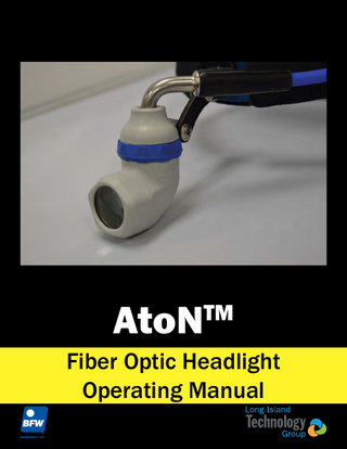
AtoN
TM
Fiber Optic Headlight Operating Manual
Table of Content
Symbol Description...2 Warnings and Cautions...3
Intended Use... 4
Overview...5
System Description... 5
Assembly and Operation...6
AtoNTM Fiber Optic Headlight... 6 Fiber Optic Cable... 7 Classic Headband... 8 Key West Headband... 9 Linkage Assembly... 10 Removing the Headlight... 11 Mounting the Headlight... 12
Cleaning and Maintenance...15
Headlight... 15
Product Configurations...16 Specifications...17 Troubleshooting and Service...18 Warranty and Service... 18
Symbol Description These important symbols may appear on your Long Island Technology Group Optic Headlight. Please note their meaning.
Attention: Read this owner’s manual for all warnings, precautions and instructions for use.
CE marking of conformity indicates this device complies with Regulation (EU) 2017/745 on medical devices.
2
Warnings and Cautions Users of this product should be thoroughly trained in the appropriate medical procedures. Also they should read and understand this owner’s manual for this headlight and all equipment used with it.
! ! ! ! ! ! ! ! ! ! ! ! ! !
WARNING! NEVER disconnect the fiber optic cable from the headlight while illuminated. Strong light emitted from the tip of the cable can cause damage or injury Read and understand the Device Operation Manual before using the device DO NOT use if packaging is damaged. DO NOT shine light into eyes. Eye injury may result Avoid prolonged contact with the headlight during use as it may be hot The Fiber Optic Cable must be Non-Conductive Standard Working Distance is 16 inches (40 cm) minimum. Use caution when operating at closer distances DO NOT use device for direct illumination of the eye DO NOT use multiple units simultaneously to illuminate the same area. High intensity illumination can cause harm to tissue Use AtoNTM only with BFWTM/Long Island Technology Group products or accessories The AtoNTM has been tested with the ChromalumeTM and HatterasTM BFWTM products and BFWTM Fiber Optic Cables. The user is responsible for safety if used with other products RX Only: United States Federal Law restricts this device to sale by or on the order of a health care professional DO NOT use this device for other than its intended use DO NOT open device. No serviceable components are inside device
3
Warnings and Cautions
! ! ! ! ! ! ! !
Distal and Proximal ends of the fiber cable become hot while in use. Allow cable to cool before disconnecting cable Only Qualified Personnel should operate the BFWTM AtoNTM Use only with BFWTM fiber optic cables For optimal performance, use HatterasTM LED Light Source DO NOT submerge the device or any of its components in liquid DO NOT subject the AtoNTM to strong shock, which include but are not limited to dropping the device on the floor DO NOT insert BFWTM Fiber Optic Cable in any port other than an ACMI/BFWTM port. Use in other ports may cause damage to the fiber optic cable or light source. DO NOT modify this equipment
Intended Use
The BFWTM AtoNTM Fiber Optic Headlight is a device intended to supply supplemental, constant and controlled illumination when used with a Light Source. This device is designed for use in the operating room. Maximum Performance is achieved when used with the BFWTM HatterasTM LED Light Source. The advantage of the AtoNTM system is that the light is positioned between the medical professionals eyes and the direction of illumination is always in the exact direction of the doctor’s vision.
4
Overview System Description
The BFWTM AtoNTM Fiber Optic Headlight is constructed of durable plastic housing encasing a precision aluminum Lens System Holder with Glass Anti-Reflective Coated Lenses and a Spot size adjusting Iris. The device is articulated, allowing the lower part of the light to be turned left and right for ease of aiming. As shown below the device is attached to a headband which allows the medical professional to wear the headlight on the head. The headband mounting system adjusts for comfortable fit and allows the light to be adjusted for position between the users eyes so illumination is shadow free. The AtoNTM also has an Iris Adjustment that allows the spot light diameter to be adjusted by simply rotating the Iris Control. Two styles of headband are available, the Classic Headband as shown below, constructed of plastic with knobs for size adjustment and the Key West headband designed to be lighter and more comfortable.
D C
B
A. B. C. D. E.
A
AtoN Fiber Optic Headlight Headband (accessory) Classic Headband (shown above) Key West Headband (not shown) Fiber Optic Cable HatterasTM LED Light Source Gown Clips TM
E
5
Assembly and Operation AtoNTM Fiber Optic Headlight
A A. B. C. D. E.
Headlight Front Lens Iris Adjustment Ring Fiber Optic Cable Input Mounting Linkage AtoNTM Dust Caps
B
C
D
E (inset)
CAUTION: PROXIMAL END OF THE CABLE MAY BE EXTREMELY HOT WHEN REMOVING FROM LIGHT SOURCE.
Fiber Optic Headlight Operation: 1. Remove the Dust Caps (E) from the Fiber Optic Headlight. 2. Install the Distal end of the Fiber Optic Cable into the Headlight Optic Cable Input (B). 3. When installing the cable into the headlight be sure to insert firmly until a distinct click is heard and felt. 4. ASSURE THE DISTAL END HAS COOLED PRIOR TO TOUCHING. When removing the Distal end of the fiber gently bending in the direction of the fiber will help click the fiber out of the headlight. 5. The lower portion of the headlight can be turned a small amount to the left and right to facilitate aiming the light. 6. The blue ring is the Iris Adjustment (B). This allows variation of the spot size projected by the headlight. 7. The Mounting Linkage (D) is adjustable for vertical aiming and position adjustment. 8. If the headlight is not going to be used for a long period of time, replace the Dust Caps (E) before storage to prevent dust build-up.
6
Assembly and Operation Fiber Optic Cable
A A. Strain Relief B. Proximal End C. Dust Cap D. Gown Clips E. Strain Relief
B
C
D F. Headband Strain Relief G. Strain Relief H. Distal End
E F
G
H
Fiber Optic Cable Types: BFWTM 9860 7’ Fiber Optic Cable BFWTM 9865: 10’ Fiber Optic Cable BFWTM 9866: 10’ Armored Cobra Coil Fiber Optic Cable
Fiber Optic Cable Usage Notes: 1. Remove the Dust Cap (C) from the end of the fiber optic cable. 2. Ensure the Gown Clips (D) are in place and securely fastened. 3. When removing the fiber optic cable from light source, grasp Strain Relief (A) to avoid damage to cable. CAUTION: PROXIMAL AND DISTAL ENDS OF THE CABLE MAY BE EXTREMELY HOT. 4. If the fiber optic cable is not going to be used for a long period of time, replace the Dust Cap (C) before storing to prevent dust build-up.
7
Assembly and Operation Classic Headband
B
A A. Distal End B. Retaining Straps C. Strain Relief D. Gown Clips E. Proximal End
C
D
E
AtoNTM Configurations (Classic Headbands): BFW 1248: optic only BFW 1265: AtoNTM Classic W/O Fiber Cable BFW 1200: AtoNTM Classic with BFW 9866 F/O BFW 1255: AtoNTM Classic with BFW 9865 F/O BFW 1260: AtoNTM Classic with BFW 9860 F/O
Directions for Use: 1. Insert the Distal End (A) of the Fiber Optic Cable into the top portion of the BFWTM AtoNTM Fiber Optic Headlight. 2. Push the cable end in as far as it will go until it clicks into position. 3. Route the cable around the left side of the Classic Headband. 4. Capture the Strain Relief (C) on the cable with the Retaining Strap (B) located on the side of the headband. 5. Capture the cable with the Retaining Strap (B) at the rear of the headband. 6. Adjust the headband for a comfortable fit. 7. If not using headband fit the dust covers to protect the optics. 8. Use the Gown Clip (D) closest to the headband for comfort. 9. Use the Gown Clip (D) nearest the Proximal end of the cable when disconnected from light source to avoid dragging and damage to the cable.
8
Assembly and Operation Key West Headband
A. Retaining Strap B. Strain Relief
A
B
AtoN Configurations (Key West Headbands): BFW 1267: AtoNTM Key West W/O Fiber Cable BFW 1252: AtoNTM Key West with BFW 9866 F/O BFW 1257: AtoNTM Key West with BFW 9865 F/O BFW 1262: AtoNTM Key West with BFW 9860 F/O TM
Directions for Use: 1. Insert the Distal End of the Fiber Optic Cable into the top portion of the BFWTM AtoNTM Fiber Optic Headlight. 2. Push the cable end as far as it will go until it clicks into position. 3. Route the cable around the left side of the Key West Headband. 4. Capture the cable under the Retaining Strap (A) located on the front of the headband. 5. Capture the cable Strain Relief (B) in the clip at the rear of the headband. 6. Adjust the headband using the straps at the rear of the band for comfortable fit. 7. Pull the straps to tightens the headband. 8. If not using the headband fit the dust covers on the headlight and the fiber optic cable to protect the optics. 9. Use the gown clip closest to the headband for comfort. 10. Use the gown clip nearest the Proximal end of the cable when disconnected from light source to avoid dragging and damage to the cable.
9
Assembly and Operation Linkage Assembly
G
B A
D C E
A. B. C. D. E. F. G. H.
!
Headband (Classic Shown) Headlight Barrel Bolt Set Screw 4 x Washers Flathead Screwdriver Allen Wrench
F H
DO NOT use Thread Locking Glue On the Linkage. Can Cause Irreparable Damage to Linkage Leading to Hazardous Situations
10
Assembly and Operation Removing the Headlight 1. Use the Allen wrench and Phillips head screwdriver to unlock the binding post.
2. Use the flathead screwdriver and Phillips head screwdriver to unscrew the binding post.
11
Assembly and Operation Mounting the Headlight 1. Place a washer on the bolt with the concave side up.
2. Place the bolt with washer into the headband mount.
12
Assembly and Operation 3. Place two more washers on the bolt. Bottom washer concave side down and the top washer concave side up.
4. Place the headlight bar and then another washer concave side down.
13
Assembly and Operation 5. Thread the screw into the bolt and tighten the binding post using the flathead and Phillips head screwdriver.
6. Place the set screw into the barrel and lock the binding post using the Allen Wrench and Phillips head screwdriver.
14
Cleaning and Maintenance Headlight 1. Clean the AtoNTM components with an alcohol wipe. 2. Only use a lens cloth or lens paper on the surface of the optic lens. 3. Use a can of compressed air to clean out any dust accumulations.
! ! !
DO NOT pour cleaning solution directly on the surface of the AtoNTM. DO NOT use any sterilization process or cleaning process using excessive heat or humidity as it will damage the device. NEVER immerse the optic in any type of liquid.
NOTE. Damaging any part of the system with the use of improper cleaning agent or cleaning process will void all warranties.
15
Product Configurations The AtoNTM Fiber Optic Headlight is available with 2 styles of headband and 3 types of Fiber Optic Cable: Headbands: 1. Classic Headband is the hard plastic traditional type shown on page 8 of this manual. 2. Key West Headband is the light weight and flexible type shown on page 9 of this manual. Fiber Optic Cables: 1. 7’ Long BFW type fiber optic cable. Not Armored 2. 10’ Long BFW type fiber optic cable. Not Armored 3. 10’ Cobra Bfw type fiber optic cable. Armored
Configuration Table: Headlight AtoN
Headband None
Fiber Optic Cable None
BFW Part No. 1248
Classic
None
1265
7’
1260
10’
1255
10’ Cobra
1200
None
1267
7’
1252
10’
1257
10’ Cobra
1262
Key West
16
Specifications Classification
Classification & Type
Mechanical LxWxH Weight
Environment
Operation Storage Relative Humidity Pressure/Altitude
Performance
Illumination Spot Size Spot Control Approved Fiber Optic Cable Approved Light Source
Class I: Medical Accessory, General Medical Equipment as to fire and mechanical hazards 1.85” x 2.34” x 1.27” 43 g 60 Degrees F (15 C) to 80 Degrees F (26.7 C) 23 Degrees F (0 C) to 104 Degrees F (40 C) 45% - 75% 860 - 1,060 hPa/2,000m 4” to 0.5” Diameter Iris, Mechanical Control BFWTM 9860, 9865, 9866 BFWTM HatterasTM, ChromalumeTM
17
Troubleshooting and Service Symptom No Light Output Can’t Change Spot Size Low Light Output
Possible Issue
Solution
Light Source is Off Fiber Optic Cable is Broken
Turn On the Light Source Replace Fiber Optic Cable Return headlight to manufacturer for repair
AtoNTM is Broken Iris is Broken Damaged Fiber Optic Cable Light Source Output is Low AtoNTM is Broken
Warranty and Service
Return the headlight to manufacturer for repair Replace Fiber Optic Cable Replace Light Source Return headlight to manufacturer for repair
Warranty against manufacturer’s defects applies to the following components of the AtoNTM under normal use for one (1) year from the date of sale from Long Island Technology Group (includes parts and labor). • LED Optics • Headband • Mounting Linkage The warranty does not cover products damaged by the following: • Accident, misuse, abuse, or alteration • Servicing by unauthorized persons • Use with unauthorized accessories • Connecting to incorrect light source In all cases Long Island Technology Group, reserves the right to determine the cause of all malfunctions and at its sole discretion will determine the damage and/or repairs that are covered under this warranty. Send All Inquires To: Long Island Technology Group, LLC 60 Carolyn Blvd Farmingdale, New York 11735 USA www.litgp.com [email protected] Tel: (631)-270-4463 Fax: (631)-414-7078
Obelis s.a. Blvd Général Wahis 53 1030 Brussels, Belgium Tel: +(32) 2.732.59.54 Fax: +(32)2.732.60.03 Email: [email protected]
18
Scan Here to See All Long Island Technology GroupTM Manuals Or Visit: http://www.litgp.com/manuals
Contents are fragile, Handle with care.
Conforms to: IEC 60601-1 Edition 3, IEC 60601-1-2 Edition 3 AAMI ES60601-1 Edition 1, CSA C22.2 NO 60601-1:08 Edition 2 Manufactured by Long Island Technology Group, LLC 60 Carolyn Blvd, Farmingdale, NY 11735
60 Carolyn Blvd, Farmingdale NY 11735 (631) 270-4463 litgp.com Revision 2.4
19
3/16/2022