BFW Inc
Headlights and headlight Charging Stations
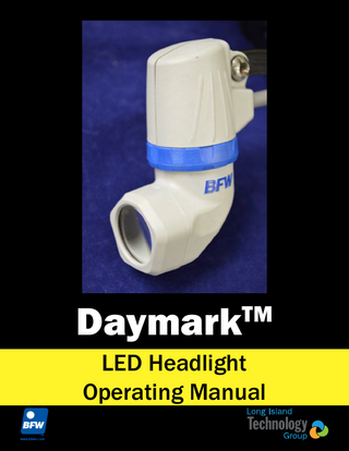
Daymark LED Headlight Operating Manual Rev-2.7 March 2022
Operating Manual
26 Pages
Preview
Page 1
Daymark
TM
LED Headlight Operating Manual
Table of Content
Symbol Description...2 Warnings and Cautions...3
Intended Use... 4
Overview...5
System Description... 5
Assembly and Operation...6
Ferrite... 6 Headlight... 7 Classic Headband... 8 Key West Headband... 8 Controller... 9 Battery... 10 Charging the Battery... 11 Linkage Assembly... 12 Removing the Headlight... 13 Mounting the Headlight... 14
Cleaning and Maintenance...17
Headlight... 17
Specifications...18 Electromagnetic Compatibility...19 Troubleshooting and Service...23 Warranty and Service... 23
Symbol Description These important symbols may appear on your Long Island Technology Group Optic Headlight. Please note their meaning.
Attention: Read this owner’s manual for all warnings, precautions and instructions for use.
CE marking of conformity indicates this device complies with Regulation (EU) 2017/745 on medical devices, Directive 2011/65/EU on the restriction of the use of certain hazardous substances in electrical and electronic equipment, and Directive 2006/66/EC on batteries and accumulators and waste batteries and accumulators.
The UL mark indicates this product has been tested to, and conforms to applicable standards.
More information for this product can be found in this operating manual.
AS TO ELECTRICAL SHOCK, FIRE AND MECHANICAL HAZARDS ONLY IEC 60601-1 Edition 4, IEC 60601-1-2 Edition 3, ANSI/AAMI E-S60601-1 (2005), CAN/CSA-C22.2 No. 60601-1 (2008)
2
Warnings and Cautions Users of this product should be thoroughly trained in the appropriate medical procedures. Also they should read and understand this owner’s manual for this headlight and all equipment used with it.
! ! ! ! ! ! ! ! ! ! ! ! ! !
WARNING! NEVER direct the device light beam into the eyes of anyone. Strong light emitted from the device can cause damage or injury. Read and understand the Device Operating Manual before using the device. Avoid prolonged physical contact with the headlight during use as it may be warm. Standard Working Distance is 16 inches (40 cm) minimum. Use caution when operating at closer distances. DO NOT use devices for direct illumination of the eye. DO NOT use multiple units simultaneously to illuminate the same area. High intensity illumination can harm tissue. Use DaymarkTM only with BFWTM/Long Island Technology GroupTM products or accessories. RX Only: United States Federal Law restricts this device to sale by or on the order of a health care professional. DO NOT subject the DaymarkTM to strong shocks, which include but are not limited to dropping the device on the floor. DO NOT use this device for anything other than its intended use. DO NOT modify this equipment. DO NOT open device. No serviceable components are inside device. Only Qualified Personnel should operate the BFWTM DaymarkTM DO NOT submerge the device or any of its components in liquid.
3
Warnings and Cautions
! ! ! ! !
DO NOT use if packaging is damaged. USE ONLY components and accessories listed on page 5 and 18 of this manual. Failure to do so may decrease system performance, may lead to unsafe operation, may negatively affect EMC performance and could result in non-compliance and could void the warranty WARNING Use of this equipment adjacent to or stacked with other equipment should be avoided because it could result in improper operation. If such use is necessary, this equipment and the other equipment should be observed to verify that they are operating normally. WARNING Portable RF communications equipment (including peripherals such as antenna cables and external antennas) should be used no closer than 30 cm (12 inches) to any part of the DaymarkTM, including cables specified by the manufacturer. Otherwise, degradation of the performance of this equipment could result. Medical Electrical Equipment needs special precautions regarding EMC and needs to be installed and put in service according to the EMC information in the Electromagnetic Capability of this manual.
Intended Use
The BFWTM DaymarkTM LED Headlight is a device intended to supply supplemental, constant and controlled illumination during medical procedures. This device is designed for use in the operating room. The advantage of the DaymarkTM system is that the light is positioned between the medical professional’s eyes and the direction of illumination is always in the exact direction of the medical professional’s vision. The intended environment for use is for Professional Health Care except for near active HF Surgical Equipment and the RF shielded room of an ME System for magnetic resonance imaging. Please follow the assembly instructions on page 6 and maintenance instructions on page 17 in order to maintain basic safety.
4
Overview System Description
The BFWTM DaymarkTM LED Headlight is constructed of durable plastic housing encasing a precision aluminum lens system holder with glass anti-reflective coated lenses and a spot size adjusting iris. Light is provided by a high power LED, driven by a solid state controller and battery to provide ON/OFF and 5 levels of light output. The system includes two spare batteries and a battery charging system. The device is articulated, allowing the lower part of the light to be turned left and right for ease of aiming. As shown below the device is attached to a headband, which allows the medical professional to wear the headlight on their head. The headband mounting system adjusts for comfortable fit and allows the light to be adjusted for position between the user’s eyes so illumination is shadow free. Two styles of headbands are available, the Classic headband as shown below, constructed of plastic with knobs for size adjustment, and the Key West headband, designed to be lighter and more comfortable. (not shown)
G
D
A A. B. C. D. E. F. G.
B C
E
F
DaymarkTM LED Headlight Headband (accessory) Classic Headband (shown above) Key West Headband (not shown) Power Cable Battery Battery Holster/Controller Battery Charger (Regular Shown) Battery Charger Power Supply
5
Assembly and Operation Ferrite
1. Open the Ferrite by pulling on the tab.
2. Attach the provided Ferrite onto the Power Cable close to the connector over-mold.
!
DO NOT use the DaymarkTM without the Ferrite as it may result in non-compliant EMC levels.
6
Assembly and Operation Headlight
D
C
B
A A. B. C. D.
Headlight Front Lens Iris Adjustment Ring Power Cable Mounting Linkage
DaymarkTM Operation: 1. The lower portion of the headlight (below the Iris Adjustment Ring) can be turned a small amount to the left and right to facilitate aiming the light. 2. The Iris Adjustment Ring (B) allows for variation of the spot size projected by the headlight. The Mounting Linkage (D) is adjustable for vertical aiming and position adjustment.
7
Assembly and Operation Classic Headband A.
Adjustment Knobs
Classic Headband Adjustment: 1. Turn the Adjustment Knobs (A) to tighten or loosen the headband.
A
Key West Headband B A. B.
A
Adjustment Tab Release Button
Key West Headband Adjustment: 1. To tighten pull on the Adjustment Tab (A). 2. To loosen press the Release Button (B) and pull on the front of the headband away from the back.
8
Assembly and Operation Controller
B
A
C
A. B. C.
Power Connector Battery Holster and Battery Side Buttons
Battery Holster/Controller: 1. Connect headlight cable to Power Connector (A), secure threaded cap tightly. 2. Attach the holster to waistband with the holster clip. 3. To turn the light on, push either of the Side Buttons (C). 4. To decrease the light level, push either of the Side Buttons (C). 5. The light level cycles from High to Low (5 levels). 6. To turn off the light, hold both Side Buttons (C) for one second.
9
Assembly and Operation Battery
Your BFWTM DaymarkTM will come with one of two versions of the 4-cell batteries shown below.
1. To Remove the battery from the holster pull the Retaining Tab (A) or pushing the battery though the Access Hatch (B) on the back of the holster.
A B
A. B.
Retaining Tab Access Hatch
2. To check the battery level, either look through the window on the bottom of the holster (Five black bars on the Battery Fuel Gauge (C) indicate a full charge) or press the Battery Fuel Gauge Button (D) on the front of the battery (Four green bars on the Battery Fuel Gauge (C) indicate a full charge). NOTE the holster will beep 15 minutes before end of life. At 5 minutes before end of life, the brightness will be limited to the two lowest levels.
C
C. D.
!
Battery Fuel Gauge (State of Charge) Battery Fuel Gauge Button
C
D
Leaving a battery in the holster will slowly drain its charge.
10
Assembly and Operation Charging the Battery
Your BFWTM DaymarkTM may come with one of two versions of battery chargers shown below. Regular on the left and Mini on the right.
A.
Charging Indicator (See Table Below)* Charging Indicator* Green Blinking Green Solid Red Blinking
A
A
Battery is currently being charged Battery is fully charged An error has occurred during charing
1. Plug the AC Cable (D) into the Power Supply (C). 2. Plug the Power Supply (C) into the Battery Charger (B). 3. Fully charging the Battery before use, will ensure the longest Battery life. When fully charged, remove the battery from charger (B).
D
B. C. D.
Battery Charger Power Supply Charger AC Cable
C
B
11
Assembly and Operation Linkage Assembly
G
H
F D
C A
B A. B. C. D. E. F. G. H.
!
E
Headband (Classic Shown) Headlight Bolt Barrel Washer X 2 Set Screw Flathead Screwdriver Allen Wrench
DO NOT use Thread Locking Glue On the Linkage. Can Cause Irreparable Damage to Linkage Leading to a Hazardous Situations
12
Assembly and Operation Removing the Headlight 1. Use the Allen wrench and Phillips head screwdriver to unlock the binding post.
2. Use the flathead screwdriver and Phillips head screwdriver to unscrew the binding post.
13
Assembly and Operation Mounting the Headlight 3. Put the linkage in-between the fork bar.
4. Place the washers concave side towards the fork on the outsides of the fork.
14
Assembly and Operation 5. Place the barrel through the left side of the fork bar.
6. Thread the bolt into the right side of the fork bar and tighten the binding post with the flathead and Phillips screwdriver.
15
Assembly and Operation 7. Place the set screw inside the barrel and tighten it using the Allen wrench and Phillips screwdriver.
16
Cleaning and Maintenance Headlight 1. Clean the DaymarkTM components with an alcohol wipe. 2. Only use a lens cloth or lens paper on the surface of the optic lens. 3. Use a can of compressed air to clean out any dust accumulations.
! ! !
DO NOT pour cleaning solution directly on the surface of the DaymarkTM DO NOT use any sterilization process or cleaning process using excessive heat or humidity as it will damage the device NEVER immerse the optic in any type of liquid
Note: Damaging any part of the system with the use of improper cleaning agent or cleaning process will void all warranties.
17
Specifications Classification
Classification & Type
Class I: Medical Accessory, General Medical Equipment as to fire and mechanical hazards
Environment
Operation Storage Relative Humidity Pressure/Altitude
60 Degrees F (15 C) to 80 Degrees F (26.7 C) 23 Degrees F (0 C) to 104 Degrees F (40 C) 45% - 75% 860 - 1,060 hPa/2,000m
Performance
Illumination Spot Size Spot Control Battery Life by Brightness Setting
Color Temperature Color Rendering Index
Mechanical
Headlight LxWxH Weight
Electrical
2.25” x 1.25” x 3.25” 25g
Device Max Electrical Rating LED Input Voltage 3-3.5 VDC Input Power 8 Watts Max Lamp Life 10,000+ hours Holster Input Voltage 14.4 VDC Input Power 45 Wh
4” Diameter Iris, Mechanical Control 25 hours at 15,000 lux (Level 1) 12 hours at 30,000 lux (Level 2) 09 hours at 40,000 lux (Level 3) 07 hours at 50,000 lux (Level 4) 05 hours at 60,000 lux (Level 5) ~5000K CCT 78 Holster w/ Battery LxWxH Weight 14.4V, 2A Charge (Regular & Mini) Input Voltage Output Voltage Line Cord (IEC 60320) Battery Output Voltage Capacity
4.75” x 3” x 1.375” 225g
24 VDC, 2.5A 11.25-14.4VDC, 2.0A Maximum Length 10ft 14.0V 3.2Ah
18
Electromagnetic Compatibility Portable and mobile RF communications equipment can affect medical electrical equipment Guidance and manufacturer’s declaration-electromagnetic emissions The Daymark
TM
Immunity Test
is intended for use in the electromagnetic environment specified below. The customer or the user of the DaymarkTM should assure that it is used in such an environment
IEC 60601 Test Level
Compliance Level
Electromagnetic Environment Guidance Portable and mobile RF communications equipment should be used no closer to any part of the DaymarkTM, including cables, than the recommended separation distance calculated from the equation application to the frequency of the transmitter. Recommended Separation Distance: Battery Operated Device
Conducted RF IEC 61000-4-6
3 Vrms 150kHz - 80 MHz
3 Vrms
Radiated RF IEC 61000-4-3
3V/meter 80 MHz 2.5 GHz
3V/m from 30MHz to 1GHz, 3V/m for 1 GHz to 25GHz; (1000 Hz 80% Modulated Test Signal)
d = 1.17√P d = 1.17√P 80 MHz to 800 MHz d = 2.23√P 800 MHz to 2.5 GHz Where P is the maximum output power rating of the transmitter in watts(W) according to the transmitter manufacturer and d is the recommended separation distance in meters (m). Field strengths from fixed RF transmitters, as determined by an electromagnetic site survey (1), should be less than the compliance level in each frequency range (2). Interference may occur in the vicinity of equipment marked with the following symbol:
19