Operating Manual
67 Pages
Preview
Page 1
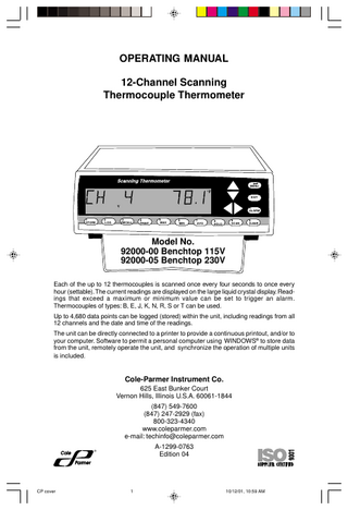
OPERATING MANUAL 12-Channel Scanning Thermocouple Thermometer
MENU
°F EXIT
+ALARM 1 STORE
2 LOG
3 RECALL
4 PRINT
5 MAX
6 MIN
7 AVG
8 HOLD
9 SCAN
0 CLEAR
Model No. 92000-00 Benchtop 115V 92000-05 Benchtop 230V Each of the up to 12 thermocouples is scanned once every four seconds to once every hour (settable). The current readings are displayed on the large liquid crystal display. Readings that exceed a maximum or minimum value can be set to trigger an alarm. Thermocouples of types: B, E, J, K, N, R, S or T can be used. Up to 4,680 data points can be logged (stored) within the unit, including readings from all 12 channels and the date and time of the readings. The unit can be directly connected to a printer to provide a continuous printout, and/or to your computer. Software to permit a personal computer using WINDOWS® to store data from the unit, remotely operate the unit, and synchronize the operation of multiple units is included.
Cole-Parmer Instrument Co. 625 East Bunker Court Vernon Hills, Illinois U.S.A. 60061-1844 (847) 549-7600 (847) 247-2929 (fax) 800-323-4340 www.coleparmer.com e-mail: [email protected] A-1299-0763 Edition 04
®
Cole Parmer
CP cover
1
10/12/01, 10:59 AM
EU Declaration of Conformity Name of Apparatus: Scanning Thermocouple Thermometer Model Number: 92000-05 Description of Apparatus: 12-Channel Benchtop Thermocouple Scanner
Barnant Company declares that the above model is in conformity to the following harmonized standards and directives: Applicable Directives
Applicable Specifications
Manufacturer’s Report Number
73/23/EEC 93/68/EEC
EN61010-1/A2: 1995
TR9866
89/336/EEC 92/31/EEC 93/68/EEC
EN61326-1/A1: 1998
TR9867
The last two digits of the year in which the current configuration of the the above model was assessed per the Low Voltage Directive is: 00. Manufacturer: Barnant Company Division Cole-Parmer Instrument Company 28W092 Commercial Avenue Barrington, IL 60010-2392 USA Tel.: 847-381-7050 Manufacturer’s Signature: 10 November, 2000 James W. Doll Vice President, Engineering
Date
Printed in U.S.A. 040101
CP cover
2
10/12/01, 10:59 AM
Introduction Safety Precautions Introduction This Scanning Thermocouple Thermometer continuously monitors temperatures at up to 12 locations. It is designed for laboratory or industrial applications for unattended temperature monitoring. An alarm is set off when any thermometer exceeds its preset minimum or maximum temperature. Temperature data is stored within the unit and can be output to a printer or PC.
Safety Precautions DANGER:
If thermocouples are at a high voltage, this voltage may be present at other points inside the instrument and outside at all the connectors.
WARNING: Disconnect or turn off power source before making connections. WARNING: Turn power off and completely disconnect instrument. Disconnect power source, thermocouples, computer, links, and printer. WARNING: Other than a lithium battery, there are no user serviceable parts inside. Replacement of the lithium battery must be performed per the Maintenance section of this Operating Manual. Refer servicing to your dealer. CAUTION: Be sure available power matches instrument power requirements. CAUTION: Protection provided by the unit may be impaired if the unit is installed and/or operated in a manner inconsistent with these instructions.
WINDOWS, WINDOWS NT - Reg TM Microsoft Corp. CENTRONICS - Reg TM Genicom Corporation Trademarks bearing the ® symbol in this publication are registered in the U.S.A. and in other countries.
1
BA 1-12
1
10/12/01, 11:01 AM
Table of Contents Page Introduction ... Safety Precautions ... Table of Contents ... Features ... Package contents ... Quick reference: Front panel controls ... Front panel display ... Rear panel connections ... Rear panel connections Thermocouple connections ... Power switch ... 10-28V DC jack ... PC/IN jack ... OUT/LINK jack ... PARALLEL PRINTER connection ... TRIGGER + GND connection ... Installation ... Front panel displays and controls 1 STORE button ... 2 LOG button ... 3 RECALL button ... 4 PRINT button ... 5 MAX button ... 6 MIN button ... 7 AVG button ... 8 HOLD button ... 9 SCAN button ... 0 CLEAR button ... MENU button ... Up-Down Arrow keys ... Left-Right Arrow keys ... EXIT button ... ALARM button ... Temperature alarms ... Other alarms ... MENU About the MENU ...
2
BA 1-12
2
10/12/01, 11:01 AM
1 1 2 4 5 6 8 8 9 9 10 10 11 11 11 12 13 14 15 16 17 18 19 19 20 20 21 21 22 23 23 23 25 26
Table of Contents continued Page MENU - How to: Set the Scale ... Change the resolution ... Enable/Disable channels ... Setup thermocouple types ... Adjust the display contrast ... Set trigger type ... Set trigger mode ... Adjust the scan rate ... Adjust the print rate ... Adjust the log rate ... Set the alarm mode ... Set the alarm print ... Set HI alarm(s) ... Set LO alarm(s) ... Set alarm hysteresis ... Adjust HI alarm setpoints ... Adjust LO alarm setpoints ... Enable/Disable the alarm beeper ... Set the date format ... Set the date ... Set the time ... Do a field calibration ... Print a calibration report ... Calibration to water ... Power up modes ... Maintenance Care and cleaning ... Battery ... Warranty ... Product Return ... Technical Assistance ... Specifications ... Appendices A Error messages ... B Guidelines to Thermocouple Selection ... C Temperature conversion ... D Menu flow chart ... E Factory default settings ...
28 29 30 31 32 33 34 35 36 37 39 40 41 42 43 44 45 46 47 48 49 50 53 55 56 57 58 59 59 59 60
62 63 63 64 66
3
BA 1-12
3
10/12/01, 11:01 AM
Features Input • Up to 12 thermocouple probes, each connected to a separate channel. • Thermocouples can be different types. • Thermocouples of types B, E, J, K, N, R, S or T can be used. • Channels can be individually enabled or disabled. Data storage • Up to 4,680 data records can be stored in the unit (a record includes readings of all 12 channels plus time and date). • Data can be logged (automatically stored). • Current data can be manually stored by pushing the STORE button. • Data is maintained even when the instrument is turned off or unplugged from power. Display • Displays the thermocouple number and temperature as scanned. • Operator can set the scan interval from a minimum of 4 seconds to a maximum of 1 hour. • Readings can be stored and displayed in °C, °F, K, or °R. • Resolution to 0.1° can be displayed. • Display can show: current, maximum, minimum, or average temperature. • Average temperature display also displays the number of readings being averaged. • Hold function freezes all 12 channels. Data output • All 12 channels can be output to a printer simultaneously. • Current, stored, or logged data can be directly sent to a printer (CENTRONICS® parallel). • Time between printing cycles is adjustable. • Current, stored, or logged data can be sent to a personal computer (PC)(RS-232 serial). Calibration • Channels can be individually calibrated manually. • Factory calibration remains in memory and can be restored at any time. Software • Software (for a PC running WINDOWS 95/98 or WINDOWS NT) is included. • Software use is optional. • Software installation instructions and software manual are on the provided CD-ROM. See readme.txt for latest information. • Software permits control of up to 8 units. • Real time data collection. • Data can be input to spreadsheet or graphing software.
4
BA 1-12
4
10/12/01, 11:01 AM
Features continued Package contents Alarms • High and low alarm temperatures can be set for each channel individually. • An open thermocouple automatically triggers an alarm. • An alarm causes the alarm icon to be displayed, and emits an audible beep. • The audible beep can be disabled. Error messages • Messages indicate channel and fault condition.
Package contents MENU
Scanning thermometer Includes wire stand for desktop convenience.
°F EXIT
+ALARM 1 STORE
2 LOG
3 RECALL
4 PRINT
5 MAX
6 MIN
7 AVG
8 HOLD
9 SCAN
0 CLEAR
Link cable RJ-11 to RJ-11 seven feet long. Use to interconnect scanning thermometer instruments. PC adapter RJ-11 to DE-9 female. Used to connect instrument to your PC, using the link cable. Trigger Connector Operating Manual This book. Warranty card AC Adapter - as supplied. Software WINDOWS 95/98 and WINDOWS NT on CD-ROM. Serial software specifications on CD-ROM. Not supplied Printer cable DB25 male to the input connection of your parallel printer.
5
BA 1-12
5
10/12/01, 11:01 AM
Quick Reference Front Panel Controls See the page number (in parenthesis) for full information about the item.
Use Left-Right arrow keys to select a channel for display. Scanning stops. Push SCAN to resume. (22) Use Up-Down arrow keys to scroll thru the MENU. Otherwise inactive. (21) MENU Push to sequence through menu choices for instrument setup. (21)
MENU
°F
EXIT Push to exit any menu or display mode. Operation continues. (23)
EXIT
+ALARM 1 STORE
2 LOG
3 RECALL
4 PRINT
5 MAX
6 MIN
7 AVG
8 HOLD
9 SCAN
ALARM Push to silence the audible alarm. Alarm icon remains. (23)
0 CLEAR
CLEAR Push CLEAR then push STORE, LOG, MAX, MIN, AVG or ALARM. Clears respective value(s) from memory. (20) SCAN Push to resume scanning display after pushing Left-Right arrow keys. Also, this immediately initiates a new scan. (20) LOG Push to toggle data logging. (14)
STORE Push to store the current set of readings in memory. “STORE” appears in the display. (13)
6
HOLD Push to freeze current display readings. Scanning continues. Left-Right arrow keys select channel displayed. To exit push HOLD. (19)
PRINT Push to turn printing on or off. (16)
RECALL Push to scroll through logged readings. Up-Down arrow keys scroll through reading numbers. Left-Right arrow keys select channel displayed. RECALL cycles through reading date, reading time, and reading temperature. Push and release EXIT to exit. (15)
MAX Push to display the maximum reading and time since last power up or last cleared. Left-Right arrow keys select channel displayed. To reset push CLEAR then MAX. To exit push EXIT. (17)
AVG Push to display the average reading and number of readings since last power up or last cleared. Left-Right arrow keys select channel displayed. To reset push CLEAR then AVG. To exit push EXIT. (19) MIN Push to display the minimum reading and reading time since last power up or last cleared. Left-Right arrow keys select channel displayed. To reset push CLEAR then MIN. To exit push EXIT. (18)
7
Quick Reference Continued Front Panel Display Rear Panel Connections 1
2
3 °F
2
4
ALARM
STORE
5
4
6
7
8
Note: Example display 1. CH and the channel number display the thermocouple that is being read. 2. The number of the channel being displayed is repeated here. 3. The temperature is displayed. 4. The temperature scale is given. 5. A flashing channel number shows a problem with that probe.
6. Words across the bottom of the display indicate status of the instrument. (Example: STORE indicates that temperature records are logged or stored.) 7. The word ALARM flashes when an alarm is present. 8. When flashing, indicates an alarm.
1. MODEL ####-##
Mfg. By Barnant Company Barrington, IL 60010-2392 USA
12 CHANNEL TERMOCOUPLE SCANNER
1
2
7
8
3 9 PC/IN
4
5
6
10
11
12
OUT/LINK
TRIGGER + GND
PARALLEL PRINTER 10-28 VDC 7-20 VAC 500 MA
2. 3. 1. 1-12 2. 3. 10-28V DC 4. PC/IN 5. OUT/LINK
6. PARALLEL PRINTER 7. TRIGGER + GND
4.
RS232
5.
6.
7.
Connect thermocouples here (two blade mini-ANSI connectors). Power switch: = on, = off. Power supply input. Connect the input connector of the supplied AC adapter here. Connect (using supplied cable) to a serial port on your PC computer (RS-232 connection). For linking additional 12-Channel Scanning Thermocouple Thermometer instruments. Connect OUT/LINK on one instrument to PC/IN, using RJ-11 connectors. Use a standard parallel printer cable (25 pin D-sub connector) to directly connect a PC printer. Connect for external events to trigger printing or data storage.
8
BA 1-12
8
10/12/01, 11:01 AM
Rear Panel Connections Thermocouple connections Power switch
A
MODEL ####-##
Mfg. By Barnant Company Barrington, IL 60010-2392 USA
12 CHANNEL TERMOCOUPLE SCANNER
1
2
7
8
3
4
9
10
PC/IN
5
6
11
12
OUT/LINK PARALLEL PRINTER
10-28 VDC 7-20 VAC 500 MA
TRIGGER + GND
RS232
B 1
2
3
4
5
6
7
8
9
10
11
12
A. Thermocouple connections • Connect up to twelve thermocouples here. • Jacks are for two blade mini-ANSI connectors. • Thermocouples of types B, E, J, K, N, R, S, or T can be used. See Appendix B for a description of thermocouple types. • Any combination of thermocouple types can be used at the same time. • If a thermocouple connection (channel) is not used it may be disabled using the Menu. See Menu - How to: Enable/Disable channels on page 30.
B. Power switch Toggle to l to turn power to the instrument on. Toggle to 0 to turn power to the instrument off. When power is turned on the display goes through a display check sequence: all display elements are turned on momentarily, then the 1,2,...12 icons (small numbers) turn off in sequence, and then the display switches to normal operation. An internal lithium battery maintains the real-time clock for power outages for over a year.
9
BA 1-12
9
10/12/01, 11:01 AM
Rear Panel Connections continued 10-28V DC jack A B PC/IN jack MODEL ####-##
Mfg. By Barnant Company Barrington, IL 60010-2392 USA
12 CHANNEL TERMOCOUPLE SCANNER
1
2
3
4
5
6
7
8
9
10
11
12
PC/IN
OUT/LINK PARALLEL PRINTER
TRIGGER + GND
RS232
10-28 VDC 7-20 VAC 500 MA
10-28 VDC 7-20 VAC 500 MA
A. 10-28V DC jack (Power supply input) Connect the input connector of the supplied AC adapter here. Polarity may be either center +, or center –, or AC. The instrument will accept: 10-28V DC (non-polarized) input @ ~ 300 mA, or 9-20V AC, 50-400 Hz @~ 500 mA. The input connector is a 2.5 mm ID, 6.4 mm OD power jack. (Switchcraft 760 or 765 or equivalent.) PC/IN
B. PC/IN jack (Computer or link connection) Computer connection Connect (using supplied cable) to a serial port on your PC computer (RJ-11 connector to DE-9 female using the RS-232 protocol). Software commands and instructions are available on the supplied CD-ROM. See package contents page 5.
Link connection Connect PC/IN (using wire with RJ-11 connectors) to OUT/LINK connection on additional instruments. Uses Linkable Instrument Network connectors and software protocol.
10
BA 1-12
10
10/12/01, 11:01 AM
Rear Panel Connections continued Out/Link jack Parallel Printer connection Trigger + Gnd connection MODEL ####-##
Mfg. By Barnant Company Barrington, IL 60010-2392 USA
12 CHANNEL TERMOCOUPLE SCANNER
1
2
3
4
5
6
7
8
9
10
11
12
PC/IN
OUT/LINK PARALLEL PRINTER
10-28 VDC 7-20 VAC 500 MA
TRIGGER + GND
RS232
A B C A. OUT/LINK jack Link connection. Connect OUT/LINK (using wire with RJ-11 connectors) to PC/IN connection on additional instruments. Uses Linkable Instrument Network connectors and software protocol. Either end of the chain can be used as the computer connection.
OUT/LINK RS232
PARALLEL PRINTER
B. Parallel Printer connection Use a standard parallel printer cable (DB-25 male to 36 position CENTRONICS male) to directly connect a PC printer. See PRINT button on page 16. No additional software or hardware is required for printing.
C. TRIGGER + GND connection Optional. Connect for external events to trigger printing or data storage. Contact closure or open collector type logic signal to ground. (Internal 5V DC pull-up through 5K ohms resistance with 100pf capacitance to ground.) Mating connector supplied.
TRIGGER + GND
TRIGGER + GND
1 2
3
4
5
Use pins 1 & 2 for contact closure. Pins 3-5 not used.
11
BA 1-12
11
10/12/01, 11:01 AM
Installation 1 MODEL ####-##
Mfg. By Barnant Company Barrington, IL 60010-2392 USA
12 CHANNEL TERMOCOUPLE SCANNER
1
2
7
8
3 9 PC/IN
4
5
6
10
11
12
OUT/LINK PARALLEL PRINTER
8
2
TRIGGER + GND
RS232
10-28 VDC 7-20 VAC 500 MA
5
6
4
1. Attach up to 12 thermocouples.
7
2
3
2. Connect the AC adapter to the instrument. 3. Plug the AC adapter into an outlet.
4 - 7 are Optional 4. Connect the PARALLEL PRINTER output to a PC printer (standard parallel port cable - not supplied). 5. Connect the PC/IN jack to a serial port of your WINDOWS PC (use the supplied cable). 6. To interconnect instruments connect the OUT/LINK jack of one Scanning Thermocouple Thermometer to the PC/IN jack of the next (cable supplied). 7. To control printing or data storage by external events, connect momentary contact events to the TRIGGER + GND connector. 8. Switch power switch to on.
12
BA 1-12
12
10/12/01, 11:01 AM
Front panel displays and controls 1 STORE button
MENU
.
°F EXIT
+ALARM 1 STORE
1 STORE
2 LOG
3 RECALL
4 PRINT
6 MIN
5 MAX
7 AVG
8 HOLD
9 SCAN
0 CLEAR
1
1 STORE button Push to store one record cycle of the current set of readings in memory. (Same as LOG, except only one record is stored.) When a numerical entry is required and the NUM icon is on, push to enter a ‘1’.
a
b
°F
STORE
The word “STORE” a and the record number being stored b appear in the display for about 3 seconds. Then the display returns to normal.
c °F
4 STORE
“STORE” c appears, and remains in the display when one or more record cycles are in storage (STORE and/or LOG). Use to save a particular data record. • A record includes readings from all 12 channels plus the time and date. • Up to 4,680 records may be stored. Memory is shared with LOG. When no more data can be stored the display reads “STORE FULL”. • To clear (erase) stored records, push CLEAR, then push STORE. “STORE” disappears from the display.
13
BA 13-25
13
10/12/01, 11:03 AM
Front panel displays and controls continued 2 LOG button
MENU
.
°F EXIT
+ALARM 1 STORE
2 LOG
3 RECALL
4 PRINT
5 MAX
6 MIN
7 AVG
8 HOLD
9 SCAN
0 CLEAR
2 2 LOG
2 LOG button Push to log record cycles as they are read. (Same as STORE, only continues automatically.) When a numerical entry is required and the NUM icon is on, push to enter a ‘2’. Push again to turn logging off. °F
4 LOG
a The word “LOG” a appears and remains in the display while records are being logged. “STORE” appears, and remains, in the display when one or more records are in storage. Use to save a particular set of data records. • Readings from all 12 channels are logged. • How often records are logged is set using the MENU - LOG procedure, page 37, which may be different from the scan rate. • The time and date of the reading is logged. • Up to 4,680 records may be logged. Memory is shared with the STORE function. When no more data can be stored the display reads “LOG FULL”. • To clear (erase) stored records, push CLEAR, then push LOG. “STORE” will disappear from the display.
14
BA 13-25
14
10/12/01, 11:03 AM
Front panel displays and controls continued 3 RECALL button
MENU
.
°F EXIT
+ALARM 1 STORE
2 LOG
3 RECALL
4 PRINT
5 MAX
6 MIN
7 AVG
8 HOLD
9 SCAN
0 CLEAR
3
3 RECALL
3 RECALL button Push to recall stored (STORE or LOG) data. When a numerical entry is required and the NUM icon is on, push to enter a ‘3’. • “RECALL” appears and remains in the display during recall. • The LOG or STORE record number and time of channel 1 are displayed first.
1 STORE RECALL
Push RECALL again to display the temperature. °F 1 STORE RECALL
Push RECALL again to display the date.
1 STORE RECALL
(continued on next page)
BA 13-25
15
15
10/12/01, 11:03 AM
Front panel displays and controls continued 3 RECALL button continued 4 PRINT button
MENU
.
°F EXIT
+ALARM 1 STORE
2 LOG
3 RECALL
4 PRINT
3
5 MAX
7 AVG
6 MIN
8 HOLD
9 SCAN
0 CLEAR
4
3 RECALL button continued • Any time during RECALL push the Up-Down arrow keys to scroll through the stored records. • Any time during RECALL push the Left-Right arrow keys to scroll through the channels. • To exit RECALL push EXIT. 4 PRINT
4 PRINT button Push to print on the printer attached to the PRINTER port. Push again to stop printing. When a numerical entry is required and the NUM icon is on, push to enter a ‘4’. • “PRINT” appears and remains in the display. • Records are printed at intervals set in the MENU. See MENU - How to adjust the print rate, see page 36. • Push PRINT again to turn off printing. Example printout: 11:59:48 04/24/99
CH CH CH
1: 5: 9:
72.9 74.5 74.7
CH CH CH
2: 6: 10:
75.7 74.5 74.1
CH CH CH
3: 7: 11:
UNDER 76.0 73.8
CH CH CH
4: 8: 12:
16
BA 13-25
16
10/12/01, 11:03 AM
74.6 74.5 73.7
Front panel displays and controls continued 5 MAX button
MENU
.
°F EXIT
+ALARM 1 STORE
2 LOG
3 RECALL
4 PRINT
5 MAX
6 MIN
7 AVG
8 HOLD
9 SCAN
0 CLEAR
5 5 MAX
5 MAX button Push to display the maximum temperature logged for each channel. The display continues to scan channels. When a numerical entry is required and the NUM icon is on, push to enter a ‘5’. °F
2
MAX
• • • •
• •
“MAX” appears and remains in the display. The time and maximum reading for a channel are displayed (since power up or last cleared). Push MAX again to switch between the time and the date. Use Left-Right arrow keys to stop scanning and to choose the channel whose maximum value is displayed. Push SCAN to return to scanning channels while remaining in MAX. Push MIN to switch the display to the minimum logged value of the displayed channel. Push EXIT to exit.
17
BA 13-25
17
10/12/01, 11:03 AM
Front panel displays and controls continued 6 MIN button
MENU
.
°F EXIT
+ALARM 1 STORE
2 LOG
3 RECALL
4 PRINT
5 MAX
6 MIN
7 AVG
8 HOLD
9 SCAN
0 CLEAR
6 6 MIN
6 MIN button Push to display the minimum temperature logged for each channel. The display continues to scan channels. When a numerical entry is required and the NUM icon is on, push to enter a ‘6’. °F
2 MIN
• • • •
• •
“MIN” appears and remains in the display. The time and minimum reading for a channel are displayed (since power up or last cleared). Push MIN again to switch between the time and the date. Use Left-Right arrow keys to stop scanning and to choose the channel whose minimum value is displayed. Push and release SCAN to return to scanning channels while remaining in MIN. Push MAX to switch the display to the maximum logged value of the displayed channel. Push EXIT to exit.
18
BA 13-25
18
10/12/01, 11:03 AM
Front panel displays and controls continued 7 AVG button 8 HOLD button
MENU
.
°F EXIT
+ALARM 1 STORE
2 LOG
3 RECALL
4 PRINT
7 AVG
5 MAX
6 MIN
7
7 AVG
8 HOLD
9 SCAN
0 CLEAR
8
7 AVG button Push to display the average temperature for each channel and the number of readings that are being averaged. The display continues to scan channels. When a numerical entry is required and the NUM icon is on, push to enter a ‘7’. °F
5 AVG
• • • •
•
“AVG” appears and remains in the display. Readings from when the instrument was last powered up or cleared are averaged. Opened channel readings are not averaged. Use Left-Right arrow keys to stop scanning and to choose the channel whose average is displayed. Push SCAN to return to scanning channels while remaining in AVG. Push AVG again to exit. 8 HOLD
8 HOLD button Push to hold the current record in display. When a numerical entry is required, and the NUM icon is on, push to enter an ‘8’. • “HOLD” appears and remains in the display. • Channel scanning, logging, printing continue normally but the display remains. • Push HOLD or EXIT to exit.
19
BA 13-25
19
10/12/01, 11:03 AM