Instructions for Use
144 Pages
Preview
Page 1
1-36-96
"Only for internal use by Draeger. Not applicable as Instructions for Use!"
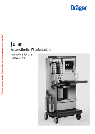
Julian
Anaesthetic Workstation
Instructions for Use Software 2.n
How to use these Instructions for Use
How to use these Instructions for Use
In the header is the subject… of the main chapter. Underneath is the title of the subchapter, to help you find your way around quickly.
Operation Selecting the ventilation mode MAN/SPONT
1
Press the »MAN/SPONT« key,
2
and confirm with the rotary knob.
"Only for internal use by Draeger. Not applicable as Instructions for Use!"
Julian
On each page… the instructions for use combining text with illustrations. The information is translated directly into actions to enable the user to learn „hands-on“ how to use the workstation.
Left-hand column: the text… provides explanations and guides the user clearly and ergonomically with brief directions on the use of the product. Bullet points indicate the steps to be followed, and where there are several steps, numbers refer to the illustration and indicate the sequence.
2 1
Display (example):
MAN/SPONT Pleth SpO2 et CO2 CO2
40
AMV 0
VT
O2
0.35 Volumeter --s -0
0
Volumeter starten:
0.5
5
1
10
Hal. N 2O
98
67
38 5.2
Freq
CO2-Al. aus/ein
8
Alarm Info
Fi
Fet
Liste
40 0.8 58
36 0.6 56
Bestätigen!
Frischgas O2 + N2O O2 %
L/min
30 4.00
Right-hand column: the illustration… provides the link with the text and serves as a guide to the workstation. Points mentioned in the text are emphasised and non-essential information is omitted. Screen displays guide the user and confirm the steps to be followed.
Frischgas intern extern
O2 flush –
For flushing and rapidly filling the breathing system and breathing bag with O2 while bypassing the Vapor unit.
3
Press the »O2 +« button. O2 flows into the breathing system without anaesthetic gas as long as the button is held down.
D
Julian
3
2
Grenzen
Kurven Konfig.
Contents
"Only for internal use by Draeger. Not applicable as Instructions for Use!"
Contents For Your Safety and that of Your Patients
5
Intended Use
7
Operating Concept
11
Before Using for the First Time
19
Preparation
21
Starting Up
25
Operation
35
Monitoring
55
Configuring in Standby Mode
81
Care
95
Julian as Wall-mounted Unit
113
Maintenance Intervals
115
Fault – Cause – Remedy
119
What's what
125
Technical Data
131
Abbreviations / Symbols
139
Index
142
3
4
"Only for internal use by Draeger. Not applicable as Instructions for Use!"
For Your Safety and that of Your Patients
For Your Safety and that of Your Patients
"Only for internal use by Draeger. Not applicable as Instructions for Use!"
Strictly follow the Instructions for Use Any use of the apparatus requires full understanding and strict observation of these instructions. The apparatus is only to be used for purposes specified here. Maintenance The apparatus must be inspected and serviced regularly by trained service personnel at six monthly intervals (and a record kept). Repair and general overhaul of the apparatus may only be carried out by trained service personnel. We recommend that a service contract be obtained with DrägerService and that all repairs also be carried out by them. Only authentic Dräger spare parts may be used for maintenance. Observe chapter "Maintenance Intervals". Accessories Do not use accessory parts other than those in the order list. Not for use in areas of explosion hazard This apparatus is neither approved nor certified for use in areas where combustible or explosive gas mixtures are likely to occur.
Safe connection with other electrical equipment Electrical connections to equipment which is not listed in these Instructions for Use should only be made following consultations with the respective manufacturers or an expert.
Liability for proper function or damage The liability for the proper function of the apparatus is irrevocably transferred to the owner or operator to the extent that the apparatus is serviced or repaired by personnel not employed or authorized by DrägerService or if the apparatus is used in a manner not conforming to its intended use. Dräger cannot be held responsible for damage caused by non-compliance with the recommendations given above. The warranty and liability provisions of the terms of sale and delivery of Dräger are likewise not modified by the recommendations given above. Dräger Medizintechnik GmbH
5
"Only for internal use by Draeger. Not applicable as Instructions for Use!"
Intended Use Contents
Intended Use
Contents "Only for internal use by Draeger. Not applicable as Instructions for Use!"
Intended Use... 9
7
8
"Only for internal use by Draeger. Not applicable as Instructions for Use!"
Intended Use
Intended Use
Intended Use Julian Anaesthetic Workstation for patients with a body weight of 5 kg and over with the use of IPPV ventilation. For the use of:
Monitoring by means of adjustable alarm limits that are automatically adapted to the ventilation mode.
"Only for internal use by Draeger. Not applicable as Instructions for Use!"
– Inhalation anaesthesia in rebreathing systems – Inhalation anaesthesia in semi-closed to virtually closed systems with "low flow" and "minimal flow" techniques (for minimal gas and anaesthetic agent consumption).
The workstation may only be used under the supervision of qualified medical personnel, so that assistance can be provided immediately in the event of any malfunctions.
– Inhalation anaesthesia in non-rebreathing systems, with separate fresh gas outlet for the connection of e.g. the Bain system or Magill system with a fresh gas flow of 0.5 to 12 L/min.
Ventilation modes: – Automatic ventilation (IPPV) and pressure-controlled ventilation (PCV).
Explosive anaesthetics, such as ether or cyclopropane, must not be used due to the risk of fire.
– Manual ventilation (MAN). – Spontaneous ventilation (SPONT).
The following measured values are displayed: – Peak pressure, mean pressure, plateau pressure and PEEP – Expiratory minute ventilation Tidal volume VT Breathing rate Patient compliance
Mobile radio telephones must not be used within 10 metres of the workstation! Mobile telephones may interfere with the operation of electrical and electronic medical equipment.
Julian must not be used with nuclear spin tomography (MRT, NMR, NMI)! Operation of the apparatus may be impaired.
– Inspiratory and expiratory concentration of O2, N2O, anaesthetic gas and CO2 optional: – Functional oxygen saturation (SpO2) and pulse rate.
The following parameters are displayed as curves: – Airway pressure – Expiratory flow – Inspiratory and expiratory concentration of O2, CO2 and anaesthetic gas optional: – Plethysmogram Trend curves and measured value lists are also available.
9
10
"Only for internal use by Draeger. Not applicable as Instructions for Use!"
Operating Concept Contents
Operating Concept
"Only for internal use by Draeger. Not applicable as Instructions for Use!"
Contents Screen ergonomics...12 Selecting / setting ventilation parameters... 14 Selecting / setting monitoring functions...15 Screen layout... 16 Three basic screens for monitoring... 17 The standard screen...17 The data screen... 17 The trend screen... 18
11
Operating Concept Screen ergonomics
Operating Concept Screen ergonomics
Monitoring
All the settings required for IPPV
– Fresh gas delivery
Pleth SpO2
"Only for internal use by Draeger. Not applicable as Instructions for Use!"
– Ventilation – Monitoring are entered on the system screen using the appropriate keys and the rotary knob. The keys are grouped in function fields:
etCO2
CO2 40
MV
0
38 _ freq Ve 6.0 10
0
O2 %
L/min
30 4.00
Middle field Monitoring
40 Hal. 0.8 N O 58
36 0.6 56 TIP:TI
PEEP
%
mbar
10
0
Pmax
VT
Freq.
mbar
mL
1/min
25 600 10
MAN SPONT
AIR
N 2O
Fresh gas delivery
The main functions for anaesthesia, e.g. selection of N2O or AIR, or selection of ventilation modes, can be selected directly by keys with permanently defined functions ("hardkeys"):
alarm info
Fet
2
Freshgas O2+N2O
alarm limits auto set limits
Fi O2
PAW
20
Right-hand field Ventilation
TI:TE
1:2
IPPV
list
.. 12...
curves config.
PCV
Ventilation
IPPV Pleth SpO2
98
67 CO2
etCO2
CO2
1 Left-hand block The »N2O« or »AIR« keys are used to select the gas to be mixed with O2 for the fresh gas mix.
40
2 Right-hand block The »MAN SPONT«, »IPPV« oder »PCV« keys select the ventilation mode.
0
MV
0
38 _ freq 6.0 Ve 10
L/min
30 4.00
AIR
N 2O
40 Hal. 0.8 N O 58
36 0.6 56 TIP:TI
PEEP
%
mbar
10
0
1
Pmax
VT
Freq.
mbar
mL
1/min
25 600 10
MAN SPONT
IPPV
2
alarm info
Fet
2
Freshgas O2+N2O
alarm limits auto set limits
Fi O2
PAW
20
O2 %
12
67 CO2
Left-hand field Fresh gas delivery
These function keys are located in the bottom row on the control panel. Left-hand block for fresh gas setting Right-hand block for ventilation
98
TI:TE
1:2
PCV
list curves config.
.. 12...
Operating Concept Screen ergonomics
Complementary "softkeys" with variable functions are provided at the bottom edge of the screen, above each group of hardkeys. These softkeys are used to set the fresh gas delivery parameters and ventilation parameters.
IPPV Pleth
etCO2
"Only for internal use by Draeger. Not applicable as Instructions for Use!"
40
MV
0
0
Freshgas O2+N2O O2 %
40 Hal. 0.8 N O 58
36 0.6 56 TIP:TI
PEEP
%
mbar
10
0
VT
Freq.
mbar
mL
1/min
30 4.00
N 2O
TI:TE
25 600 10
1
The current parameter values are displayed in the softkey field.
1:2
MAN SPONT
AIR
IPPV
config.
PCV
SpO2
98
67 CO2
etCO2
CO2 40
MV
0
38 _ freq Ve 6.0 10
0
O2 %
L/min
30 4.00
Fet
36 0.6 56
TI:TE
TIP:TI
PEEP
%
mbar
1:2
10
0
Pmax
VT
Freq.
mbar
mL
1/min
25 600 10
– to set and confirm the monitoring functions. N 2O
AIR
MAN SPONT
alarm info
Fi
2
Freshgas O2+N2O
alarm limits auto set limits
40 Hal. 0.8 N O 58
O2
PAW
20
– to set and confirm the parameters for fresh gas and ventilation modes,
.. 12...
curves
2
Pleth
– to confirm the selected carrier gas or a ventilation mode,
list
IPPV
In a prominent position at the bottom right-hand side:
4 confirm = press
alarm info
Fet
Pmax
L/min
alarm limits auto set limits
Fi
2
These softkeys have different functions, depending on the operating status or ventilation mode.
3 select = turn
38 _ freq Ve 6.0 10
O2
PAW
20
2 Right-hand block: The keys for setting the parameters for the relevant ventilation mode. The example shows the parameters for IPPV controlled ventilation.
The "turn-and-push" rotary knob is the main operating control of the apparatus and has the following functions in all setting operations:
67 CO2
CO2
1 Left-hand block: The keys for setting the O2 concentration and fresh gas flow.
98
SpO2
list
.. 12...
curves config.
3 IPPV
PCV
Beside the rotary knob: The standby key E for switching over to standby mode. 5 Press standby key E and confirm by pressing the rotary knob.
5 4
13
Operating Concept Screen ergonomics
Selecting / setting ventilation parameters
Julian
Example: PEEP ventilation parameter 1 Press the softkey »PEEP«. 2 Select the PEEP value = turn the rotary knob.
"Only for internal use by Draeger. Not applicable as Instructions for Use!"
3 Confirm the PEEP value = press the rotary knob.
1 2
3
The keys for the various monitoring functions are located on the right-hand side of the screen.
IPPV Pleth SpO2
These keys also have different functions = softkeys, depending on the monitoring screen required.
98
etCO2
CO2 40
MV
0
38 _ freq Ve 6.0 10
0
O2 %
L/min
30 4.00
N 2O
AIR
Fet
36 0.6 56 TIP:TI
PEEP
%
mbar
10
0
Pmax
VT
Freq.
mbar
mL
1/min
25 600 10
MAN SPONT
IPPV
alarm info
Fi
2
Freshgas O2+N2O
alarm limits auto set limits
40 Hal. 0.8 N O 58
O2
PAW
20
14
67 CO2
TI:TE
1:2
PCV
list curves config.
.. 12...
Operating Concept Screen ergonomics
Selecting / setting monitoring functions
Julian
For example, to change the lower alarm limit of the endtidal CO2 concentration.
1
"Only for internal use by Draeger. Not applicable as Instructions for Use!"
1 Press the »alarm limits« softkey. The alarm limits menu is displayed on the screen.
IPPV Pleth
98 67 etCO 38 MV 6.0 29 FiO FiHal. 0.8
-95
alarm limits
120 50
auto set limits
42 30
alarm info
SpO2
CO2 40
2
0
PAW
20
-3.0
list
-20
curves
2
1.0 0.0
0
config.
40 8
PAW
Select limit: Turn and confirm ! ! Freshgas O2 + N2O Pmax O2 %
L/min
50 1.00
●
VT mL
Freq.
TI:TE
1/min
TIP:TI
PEEP
%
mbar
25 600 10 1:2 10
IPPV Pleth
Set the alarm limit value = turn the rotary knob.
98 67 etCO 38 6.0 MV FiO 29 FiHal. 0.8
-95
alarm limits
120 50
auto set limits
42 30
alarm info
SpO2
●
0
Select the alarm limit value = turn the rotary knob. Confirm the selection = press the rotary knob. The limit value is highlighted. Example: lower alarm limit etCO2: <30
●
mbar
Confirm the new alarm limit = press the rotary knob. The cursor returns to the zsymbol.
CO2 40
2
0
-20
2
PAW
20
-3.0
1.0 0.0
0
curves config.
40 8
PAW Adjust limit value: Turn and confirm
list
!
Freshgas O2 + N2O O2 %
L/min
50 1.00
Pmax
VT
Freq.
mbar
mL
1/min
TI:TE
TIP:TI
PEEP
%
mbar
25 600 10 1:2 10
0 15
Operating Concept Screen ergonomics Screen layout
Exit the alarm limits menu:
Julian
"Only for internal use by Draeger. Not applicable as Instructions for Use!"
1 Press the rotary knob or 2 Press the Q key.
2 1
The function keys for standard functions are located on the right-hand side of the control panel.
IPPV Pleth
G Suppress the acoustic alarm for 2 minutes. S Select the screen page. Q Back to standard page.
98
SpO2
etCO2
CO2 40
MV
0
0
Fi
Fet
40 Hal. 0.8 N O 58
36 0.6 56 TIP:TI
PEEP
%
mbar
10
0
2
Freshgas O2+N2O O2 %
L/min
30 4.00
Screen layout ➀ Status field:
Pmax
VT
Freq.
mbar
mL
1/min
MAN SPONT
➀
Displays information on the current operating mode
TI:TE
25 600 10
AIR
N 2O
1:2
IPPV
➂
For numerical values
➄ Lower softkeys – for fresh gas parameters ➅ Prompt field: For user guidance
➆ Lower softkeys – for ventilation parameters ➇ Right-hand softkeys – for monitoring: For rapid selection of the desired monitoring function
16
.. 12...
curves config.
➃
IPPV Pleth SpO2
For curves and bargraphs
➃ Numerical value field:
list
PCV
➁
➁ Graphics field:
Displays information on the alarms, warnings, etc. and their priority
alarm limits auto set limits
38 _ freq Ve 6.0 10 alarm info
O2
PAW
20
➂ Alarm field:
67 CO2
98
67 CO2
etCO2
CO2 40
MV
0
0
O2 %
L/min
30 4.00
➄
Fet
36 0.6 56 TIP:TI
PEEP
%
mbar
10
0
Pmax
VT
Freq.
mbar
mL
1/min
25 600 10
➅
➆
alarm info
Fi
2
Freshgas O2+N2O
auto set limits
40 Hal. 0.8 N O 58
O2
PAW
20
38 _ freq 6.0 Ve 10
alarm limits
TI:TE
1:2
list curves config.
➇
Operating Concept Screen layout
Three basic screens for monitoring To call up the standard screen, data screen and trend screen in succession:
Julian
"Only for internal use by Draeger. Not applicable as Instructions for Use!"
1 Briefly press the S key until the desired screen is displayed.
2 1
Back to the standard screen: 2 Press the Q key.
The fresh gas and ventilation parameters can be set by means of the softkeys in each of the three basic screens.
The standard screen with three selectable curves. The most important numerical values are displayed in groups on the right-hand side of the screen.
IPPV Pleth
98
SpO2
67 CO2
etCO2
CO2
Ve
40
MV
0
0
O2 %
L/min
30 4.00 The data screen contains all the numerical values with their units of measure.
Pmax
VT mL
mbar
alarm info list
Fet
40 Hal. 0.8 N O 58
36 0.6 56
Freq.
TIP:TI
PEEP
%
mbar
10
0
2
Freshgas O2+N2O
auto set limits
Fi O2
PAW
20
38 _ freq 6.0 10
alarm limits
TI:TE
1/min
25 600 10
1:2
27 20 5 15 65
98
curves config.
IPPV PAW
peak plat.
40
PEEP mean compliance
mbar
6.0 VT 0.60 freq 10 AW-temp. 34
0
67 1/min Fet
Fi CO2 mmHg
0 O 40 % Hal. 0.8 % NO 58 %
36 33 0.6 56
2
mL/mbar
20
MV
SpO2 %
L/min L
2
1/min °C
01. Nov. 98
12 : 00
sys. comp. 6.40 mL/mbar leckage 10 mL/min
alarm limits auto set limits alarm info list
config.
01-10 8 : 00
Freshgas O2 + N2O Pmax O2 %
L/min
50 1.00
mbar
VT mL
Freq.
TI:TE
1/min
25 600 10
1:2
TIP:TI
PEEP
%
mbar
10
0
17
Operating Concept Screen layout
The trend screen displays the recorded progress of the numerical values over time since measurement started. The current measured values are displayed on the right-hand side.
IPPV PAW 60
SpO2 40
98
67
30
CO2
etCO2
Display (example):
0 11:00
Trends for CO2 and minute ventilation MV
CO2
20
12:00
13:00
MV
38 _ freq Ve 6.0 10 Fi
Fet
40 Iso. 0.8 N O 58
36 0.6 56
MV 15
O2
"Only for internal use by Draeger. Not applicable as Instructions for Use!"
10
0
5
2
0
Select zoom area: Turn
Zoom in: Press
!
alarm limits CO2 MV AGas N 2O O2 compl. SpO2 pulse full trend
!
Freshgas O2 + N2O O2 %
L/min
50 1.00
18
Pmax
VT
Freq.
mbar
mL
1/min
25 600 10
TI:TE
TIP:TI
PEEP
%
mbar
1:2 10
0
Before Using for the First Time Contents
Before Using for the First Time Contents
"Only for internal use by Draeger. Not applicable as Instructions for Use!"
Charging the battery for emergency operation... 20 When Julian is not in use... 20
19
Before Using for the First Time Charging the battery for emergency operation When Julian is not in use
Before Using for the First Time
"Only for internal use by Draeger. Not applicable as Instructions for Use!"
Fit the enclosed O2 sensor, page 117 "Replacing O2 sensor" Fit the flow sensor, page 106
Charging the battery for emergency operation Julian has a built-in uninterruptible power supply UPS which maintains the power supply for 30 minutes in the event of a mains failure, provided that the battery is charged. The switch-over to the battery-powered UPS is automatic and is indicated on the screen by the message: POWER FAIL! The battery recharges automatically when the workstation is plugged into the mains.
1 The battery must be charged for 10 hours before using the Workstation for the first time. ●
Plug the mains plug of the Julian workstation into the mains socket. The mains voltage must correspond to the voltage specified on the nameplate.
1 The green LED ●
N lights up.
Leave Julian connected to the mains for 10 hours. The workstation does not have to be switched on.
The devices connected to auxiliary power sockets will not be powered by the UPS in the event of a power failure.
When Julian is not in use ●
Charge battery at least every 4 weeks. Allowing it to run down can lead to damage.
If Julian is out of use for an extended period: ●
Leave the workstation connected to the mains at all times.
1 The green LED
20
N is lit.