Technical Documentation
314 Pages
Preview
Page 1
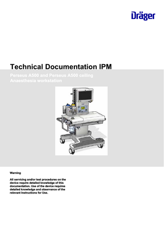
Technical Documentation IPM Perseus A500 and Perseus A500 ceiling Anaesthesia workstation
Warning All servicing and/or test procedures on the device require detailed knowledge of this documentation. Use of the device requires detailed knowledge and observance of the relevant Instructions for Use.
No.2805_0000005555-002
This page intentionally left blank.
2
Perseus A500 and Perseus A500 ceiling
Technical Documentation IPM
Table of contents
No.2805_0000005555-002
Table of contents General 1 General notes ... Abbreviations 1 Abbreviations and definitions... Function descriptions 1 System overview ... 2 Control panel (ECD) ... 3 Gas cylinder pressure regulators (option) ... 4 Mixer unit ... 5 Breathing system and interface ... 6 Blower (M3.1) ... 7 Anaesthetic gas system (AGS)... 8 Anaesthetic vaporizer (Vapor) ... 9 General points on the "Vapor View" ... 10 Optional Vapor View (M605) ... 11 Fan ... 12 Power supply unit(M7.3) ... 13 Power failure backup battery ... 14 Main A500 PCB ... 15 Therapy Control Unit PCB (M16.2)... 16 Blower A500 PCB ... 17 M21 EAST PCB (M21, RFID unit) ... 18 Ventilation Sensor PCB (M4.6)... 19 PGM (M5x) ... 20 Auxiliary sockets without isolating transformer ... 21 Auxiliary sockets with 240 Volt isolating transformer (option)... 22 Central brake ... 23 Bronchial suction device... Maintenance instructions 1 General information on use of maintenance instructions ... 2 Safety instructions ... 3 Cut the power to the device before carrying out the procedure... 4 AGS filter (filter in anaesthetic gas mounting system) ... 5 Sampling gas return filter... 6 Water trap mount; replacing the O-rings ... 7 Filter mat on PGM fan ... 8 Filter mat on power supply unit fan... 9 Cylinder pressure regulator, seal on cylinder connection ... 10 Cylinder pressure regulator, sintered-metal filter on cylinder connection ... 11 Cylinder pressure regulator, diaphragm unit ... 12 Cylinder pressure regulator, general overhaul ... 13 Replacing the lead-gel battery (2x)... 14 Integrated power supply unit P2500 of an IACS... 15 Replacing the fuse and the batteries ... Technical Documentation IPM
Perseus A500 and Perseus A500 ceiling
5 6 9 10 13 14 21 25 28 42 49 51 53 54 57 62 64 69 71 77 80 86 89 93 105 108 111 113 119 120 121 122 124 127 134 136 138 140 142 143 148 156 162 167 3
Table of contents
171
No.2805_0000005555-002
Annex
4
Perseus A500 and Perseus A500 ceiling
Technical Documentation IPM
General
This chapter contains general notes and definitions that are important for the use of this documentation.
General notes ...
6
No.2805_0000005555-002
1
Technical Documentation IPM
Perseus A500 and Perseus A500 ceiling
5
General General notes
1
General notes
1.1
Notes on use Read through the following notes thoroughly before applying this documentation. Dräger reserves the right to make changes to the device and/or to this documentation without prior notice. This documentation is intended solely as an information resource for maintenance personnel or technical specialists.
1.2
Copyright and other protected rights The content of this documentation, in particular its design, text, software, technical drawings, configurations, graphics, images, data and their selection and its composition and any amendments to it (content) are protected by copyright. The content must not (in whole or in part) be modified, copied, distributed, reproduced, republished, displayed, transmitted or sold without the prior written consent of Dräger.
1.3
Definitions WARNING An important advisory indicating a potentially hazardous situation which may result in death or serious injury if not prevented. CAUTION An important advisory indicating a potentially hazardous situation which may result in minor or moderate injury to the user or patient or in damage to the medical product or other assets if not prevented. NOTE A NOTE provides additional information intended to avoid inconvenience during operation and/or servicing. Term Maintenance
Maintaining the operative condition of a medical product by suitable means
Inspection
Assessment of the actual condition of a medical product
Servicing
Maintaining the operative condition of a medical product by recurrent, specified measures
Repair
Restoring the operative condition of a medical product after failure of a device function
General safety precautions Read through each section thoroughly before beginning servicing. Always use the correct tools and the specified test equipment. Otherwise the device may not work correctly or may be damaged.
6
Perseus A500 and Perseus A500 ceiling
Technical Documentation IPM
No.2805_0000005555-002
1.4
Definition
General General notes
WARNING The device must be regularly inspected and serviced by maintenance personnel. Repairs and complex maintenance work on the medical product must be carried out by qualified specialists. If you require a service contract, or for any necessary repair work, Dräger recommends DrägerService. Dräger recommends using original Dräger parts for servicing. If the aforementioned instructions and recommendations are ignored, the correct functioning of the medical product may be put at risk. Pay attention to the "Servicing" section of the Instructions for Use. WARNING Non-conforming test values If test values do not conform to specifications, the safety of the patient may be put at risk. –
Do not put the device into operation if test values do not conform to specifications.
–
Contact your local service organization.
WARNING Impermissible modifications to the device If impermissible modifications are made to the device, the safety of the patient may be put at risk. Do not modify the device without Dräger's permission. WARNING Risk of infection The unit may transmit pathogens following use on the patient. –
Before carrying out any servicing, ensure that the device and its components have been handed over by the user cleaned and disinfected.
–
Service only cleaned and disinfected units and unit components.
WARNING Risk to patient. Ensure that no patient is connected to the device before starting maintenance or repair work. NOTE
No.2805_0000005555-002
Where reference is made to legislation, regulations and standards, in respect of devices used and serviced in Germany they are based on the laws of Germany. Users and technicians in other countries must comply with their national laws and/or international standards.
Technical Documentation IPM
Perseus A500 and Perseus A500 ceiling
7
General
No.2805_0000005555-002
General notes
8
Perseus A500 and Perseus A500 ceiling
Technical Documentation IPM
Abbreviations
This section contains a list of the abbreviations used in this document.
Abbreviations and definitions...
10
No.2805_0000005555-002
1
Technical Documentation IPM
Perseus A500 and Perseus A500 ceiling
9
Abbreviations Abbreviations and definitions
10
Abbreviations and definitions A
Ampere
AGFS
Anaesthetic gas scavenging system
AGS
Anaesthetic gas system
AIR
Medical compressed air
APL
Adjustable Pressure Limit
Aux. O2
O2 insufflation
Operator control unit
Display and operating unit
cmH2O
Centimetres head of water
CO2
Carbon dioxide
COM
Serial port
DVI
Digital Video Interface
EEPROM
Electrically Eraseable Programmable Read Only Memory
EMV
Electro Magnetic Compatibility
ESD
Electro Static Discharge
FG
Fresh gas
Flash-ROM
Flash Read Only Memory
FTP
File Transfer Protocol
Unit
Perseus A500 anaesthesia workstation system
hPa
Hectopascal
Hz
Hertz
I:E
Inspiratory-to-expiratory time ratio
ID
Identification
ILCA2
Infrared Gas Analyzer
kg
Kilogram
L
Litre
LAN
Local Area Network
LED
LED
MAC
Minimum Alveolar Concentration
MAN/ SPON
Manual ventilation/spontaneous breathing
mbar
Millibar
mmHg
Millimetres of mercury
MV
Minute volume
N 2O
Nitrous oxide, dinitrogen monoxide
Ncm
Tightening torque
Nm
Tightening torque
O2
Oxygen
O2+
O2 flush
Pa
Pascal, unit of pressure
PEEP
Positive end-expiratory pressure
Perseus A500
Name of anaesthesia workstation system
Perseus A500 and Perseus A500 ceiling
Technical Documentation IPM
No.2805_0000005555-002
1
Abbreviations Abbreviations and definitions
Inspiratory pressure
PLD
Programmable Logic Device
PWM
Puls Width Modulation = Pulse Width Modulation
RAM
Random Access Memory
RFID
Radio Frequency Identification
SDRAM
Synchronous Dynamic RAM
SNMP
Simple Network Management Protocol
SPI
Serial Peripheral Interface
SRAM
Static RAM
SVF
Smart Vaporizer Function
TFT
Thin Film Transistor
UAR
Universal Asynchronous Receiver/Transmitter
USB
Universal Serial Bus
USV
Uninterruptible Power Supply
V
Volt
VT
Breath volume
No.2805_0000005555-002
Pinsp
Technical Documentation IPM
Perseus A500 and Perseus A500 ceiling
11
Abbreviations
No.2805_0000005555-002
Abbreviations and definitions
12
Perseus A500 and Perseus A500 ceiling
Technical Documentation IPM
Function descriptions
This chapter contains descriptions of the device's technical functions.
System overview ... Control panel (ECD) ... Gas cylinder pressure regulators (option) ... Mixer unit ... Breathing system and interface ... Blower (M3.1) ... Anaesthetic gas system (AGS)... Anaesthetic vaporizer (Vapor) ... General points on the "Vapor View" ... Optional Vapor View (M605) ... Fan ... Power supply unit(M7.3) ... Power failure backup battery ... Main A500 PCB ... Therapy Control Unit PCB (M16.2)... Blower A500 PCB ... M21 EAST PCB (M21, RFID unit) ... Ventilation Sensor PCB (M4.6)... PGM (M5x) ... Auxiliary sockets without isolating transformer ... Auxiliary sockets with 240 Volt isolating transformer (option)... Central brake ... Bronchial suction device...
14 21 25 28 42 49 51 53 54 57 62 64 69 71 77 80 86 89 93 105 108 111 113
No.2805_0000005555-002
1 2 3 4 5 6 7 8 9 10 11 12 13 14 15 16 17 18 19 20 21 22 23
Technical Documentation IPM
Perseus A500 and Perseus A500 ceiling
13
Function descriptions System overview
1
System overview
1.1
Introduction The following presents the Perseus A500 anaesthesia workstation. The various sections of the function description detail the precise functioning of the individual components. The Perseus A500 anaesthesia workstation is referred to in the following as "the device".
Design
13573
1.2
Fig. 1
Designation
Item
1
Control panel with work surface illumination.
8
Trolley
2
Mixer unit
9
Anaesthetic gas system (AGS).
3
Work surface
10
CO2 absorbers
4
Pull-out table top (optional).
11
Breathing system.
5
Central brake
12
APL valve
6
Castors, centrally braked.
13
External fresh gas outlet (optional).
14
Perseus A500 and Perseus A500 ceiling
Technical Documentation IPM
No.2805_0000005555-002
Item
Front view of device
Function descriptions System overview
Item
Item
Foot rest
14
Plug-in connection for vaporizers with optional "Vapor View".
Technical Documentation IPM
Perseus A500 and Perseus A500 ceiling
No.2805_0000005555-002
7
Designation
15
Function descriptions
Component structure
Fig. 2
Component structure
13582
1.3
No.2805_0000005555-002
System overview
16
Perseus A500 and Perseus A500 ceiling
Technical Documentation IPM
Function descriptions System overview
Designation
Function
Control panel (ECD) Controls
Rotary knob and buttons.
LCD module
TFT LCD (WXGA, 15.32 inch).
LEDs
Illuminate the work surface (table).
GUIμC PCB (M596)
Connects the graphics microcontroller and the peripheral functions.
Touch-panel
Touch-sensitive surface.
Column Fan 2
Regulates the temperature and prevents impermissible O2 enrichment in the mixer unit.
Mixer unit
The mixer unit generates the desired fresh gas from N2O, AIR and O2.
Vapor View (M605) (option)
The function unit illuminates the vaporizers, reads out vaporizer data (from suitable vaporizer models) and transfers the data to the device.
VSWAK
A-cone valve for the external fresh gas outlet (optional).
Auxiliary sockets
Connections for external devices (electrically isolated from the mains by an isolating transformer).
Table (work surface) Breathing system
Controls the gas flow from the ventilator to the patient. Gas breathed back into the breathing system has CO2 removed from it by means of a soda lime absorber and is re-used.
Blower (M3.1)
Generates the preset airway pressure.
Blower capacitor (68 mF)
Buffer capacitor for the blower in the ventilator.
Ethernet switches
Only suitable for connection of devices or networks which have only a safety low voltage (SELV) even in case of fault.
Device rocker switch
Main switch.
Plug for non-heating apparatus
Connection for power cable (100 to 240 V).
Loudspeaker
Acoustic interface for alarms and notifications.
Blower A500 PCB
Power electronics to actuate the blower, the breathing system heater and valves in the ventilator.
Main A500 PCB
Connects the PCBs to the modules and other device components.
External Temp. Sensor Measures the ambient temperature. PCB Therapy Control Unit PCB (M16.2)
Microprocessor module to control and monitor anaesthesia units.
Fan 1, 3
In the device, fan 1 and 2 of the oxygen reduction and fan 3 for temperature regulation.
No.2805_0000005555-002
M21 EAST PCB (M21) Transponder detection by RFID technology. Power supply unit(M7.3)
DC power supply for the device and battery charge management.
PGM (M5x)
The patient gas module is a complete, suction-based gas analyzer system.
Interfaces
Serial ports (COM 1 and COM 2), USB port and connection for an optional lamp.
Trolley
Technical Documentation IPM
Perseus A500 and Perseus A500 ceiling
17
Function descriptions System overview
Designation
Function
Batteries
Two 12 Volt lead/gel batteries (for uninterruptible power supply (UPS)).
NTC
Measures the battery temperature during charging by the power supply unit.
Isolating transformer
Isolates the auxiliary sockets electrically from the mains.
Components beneath the work surface
12548
1.4
Fig. 3
Item
Overview of components and connections beneath the work surface
Designation
Item
Designation
PGM (M5x) (Patient Gas Module).
8
Therapy Control Unit PCB (M16.2).
2
Blower capacitor (not visible under PGM).
9
Main A500 PCB.
3
Ventilation Sensor PCB (M4.6).
10
Rocker switch.
4
Breathing system (beneath it is the pneumatic interface).
11
Power supply unit (M7.3).
5
M21 EAST PCB (M21)(RFID).
12
External Temp. Sensor PCB (beneath loudspeaker).
6
Cover for Blower A500 PCB.
13
Loudspeaker.
7
Connector to control panel.
-
-
No.2805_0000005555-002
1
18
Perseus A500 and Perseus A500 ceiling
Technical Documentation IPM
Function descriptions System overview
Connections
No.2805_0000005555-002
12683
1.5
Fig. 4
Overview of connections
Item
Designation
Item
Designation
1
PGM (M5x).
14
Plug-in fuse.
2
Fan 1.
15
Fuse for power supply unit.
3
Optional "Vapor View" (M605)
16
Power supply unit (M7.3).
4
Mixer unit.
17
Feed from isolating transformer (option) or from inlet connector for non-heating apparatus.
5
"A-cones" option (VSWAK).
18
Loudspeaker.
6
Main A500 PCB.
19
External Temp. Sensor PCB (beneath loudspeaker).
7
Interfaces of the Main A500 PCB.
20
Operator control unit with workstation light.
8
Rocker switch.
21
M21 EAST PCB (RFID, M21).
9
Therapy Control Unit PCB (M16.2).
22
PEEP valve (M595).
10
Fan 3.
23
Ventilation Sensor PCB.
11
Batteries (2x).
24
Blower (M3.1) (with fan M3 in mount).
12
Temperature sensor (charge management).
25
Blower capacitor (68 mF).
Technical Documentation IPM
Perseus A500 and Perseus A500 ceiling
19
Function descriptions System overview
Item
Holder for plug-in fuse.
Item 26
Designation Blower A500 PCB.
No.2805_0000005555-002
13
Designation
20
Perseus A500 and Perseus A500 ceiling
Technical Documentation IPM