
Australian Made. Internationally Trusted & Used.
Welcome to BioClinical Services
One-Click, Instant, Standardised Access from your hospital intranet to whatever documentation you need:
Instructions for Use
Cleaning & Sterilisation Instructions
Procedure Guides
Product Recalls and Alerts
Skills Checklists
User Guides
Pocket Reference Guides
Addendums
In-Service Videos
and more
Try a Demo
Book a walkthrough for you and your team
Important Accreditations and Compliance Information
BioClinical Services to the rescue!
Rate Action 3.17 as satisfactorily met only if a health service organisation demonstrates progress towards full implementation as set out in their implementation plan for AS/NZS 4187:2014
AS/NZS 2500:2020 requirements
5.4 Documentation
A prime responsibility of the administration of a responsible organization is to ensure that proper and adequate documentation systems are established and observed. Such systems should include, but not necessarily be limited to, the following:c) Supply and availability of equipment documentation, including operating instructions, service records, fault reports, and hazard tags.
5.5.3 Operator instructions
Most equipment requires some operator proficiency. Formal instruction of staff in operation of equipment should be performed, particularly for new staff or new equipment. User manuals, written in English and in terms acceptable to the user, should be available to the user at all times, and positioned near the equipment. Colour illustrations should not be relied upon as the sole means of identifying or clarifying important instructions or warnings.AS/NZS 4187:2014 requirements
a) Complete a gap analysis to determine the current level of compliance and document the findings. Access to the standard and relevant references outlined in AS/NZ 4187:2014 are also necessary to ensure that the health service organisation's action plan is comprehensive and addresses gaps within the organisation. Without access to these references the health service organisation cannot adequately assess gaps and can therefore not adequately plan for them.
b) Develop and document a detailed implementation plan using quality improvement principles specifying timeframes, milestones and deliverables to enable full implementation of AS/NZS 4187:2014 over a five year period, from December 2016.
c) Implement the plan and demonstrate progress toward implementation.
MHRA Managing Medical Devices January 2021 Guidance for healthcare and social services organisations
7.1 Instructions for Use
Clear responsibilities should exist for ensuring that the manufacturer’s instructions are passed on to all usersCQC Care Quality Commission Regulation 15: Premises and equipment
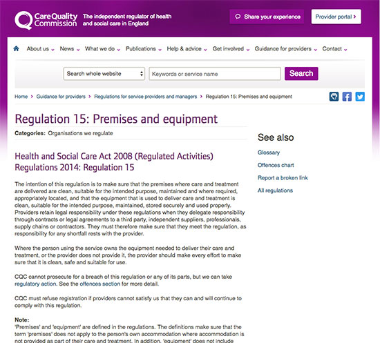
There should be suitable arrangements for the purchase, service, maintenance, renewal and replacement of premises (including grounds and equipment. These arrangements must make sure that they meet the requirements of current legislation and guidance, manufacturers' instructions and the provider's policies or procedures.
All equipment must be used, stored and maintained in line with manufacturers' instructions. It should only be used for its intended purpose and by the person for whom is it provided.
CQC Care Quality Commission Standardisation
An organisation-wide equipment and medical devices management policy that covers: acquisition, record-keeping and equipment inventories; availability of manufacturers' instructions for use; training; repair and maintenance; single use devices use; decommissioning; disposal and actions required on manufacturers' corrective action notices.
Stay Informed
Pricing Structure
We offer discounts for 3 year contracts and groups of hospitals, even further discounts for small hospitals. Contact us for current pricing.
Individual Hospitals
Save 10% on individual libraries on a 3 year contract
Save 20% on both libraries on a 3 year contract
Groups of 3 or more hospitals
Save 25% on both libraries on a 3 year contract if each hospital has>100 beds
Save 35% on both libraries on a 3 year contract if each hospital has<100 beds
Contact Us
Chat to us instantly online right now, call or email our core team directly. Get in touch about anything and everything.