FUKUDA DENSHI
DYNASCOPE 8000 Series Central Monitors
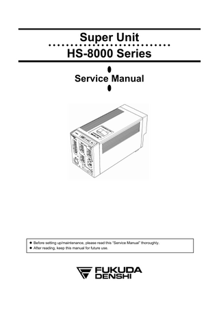
Super Unit HS-8000 Series Service Manual Edition 1 Aug 2011
Service Manual
132 Pages
Preview
Page 1
●
●
●
Super Unit HS-8000 Series
● ●
●
●
●
● ●
●
●
●
● ●
●
●
●
● ●
●
●
●
● ●
●
Service Manual
z Before setting up/maintenance, please read this “Service Manual” thoroughly. z After reading, keep this manual for future use.
●
●
Service manual Delivery Notice Service Manual (No.
): Q’ty 1
Please confirm your receipt of the above service manual by filling in and sending us back this sheet by return. Delivery of Service Manual
Please note that this service manual is a confidential document and needs to be kept with an utmost care under person in charge. If the technical drawing in the service manual is unreadable, you can request it to us by specifying a page or a part. When you have received this service manual, verify that there is no paging disorder or missing page. You are requested to kindly fill the underlined area below in this sheet and send it back to us after verification. Please be noted that photocopying of this manual is strictly prohibited. Also, for improvement of the future service manual, your comment and request will be appreciated. If you have any comment or request on usability, viewability, readability, or if you notice anything hard to understand on this service manual, please inform it to us. Fukuda Denshi Co., Ltd. Development & Production Support Dept. 2-35-8 Hongo Bunkyo-ku, Tokyo, 113-8420 Japan
Received by of (Company/Hospital) on the day of
Revision History Model Name HS-8000 Series Edition 1
-
Service Manual Revised Items
Reason of the Revision New Edition
Revised Date 2011.8
Blank Page
Preface Before using this product, read the following precautions to make sure the product is used correctly and safely.
Safety Precautions·························································· ii Graphic Symbols ·························································· ii Precautions for Safe Operation of Medical Electrical Equipment ··································································· iii Precautions about the Maintenance ···························· iv Precautions about the Pacemaker······························· iv Non-Explosion Proof·····················································v Defibrillation Safety·······················································v Precautions about the Mason-Likar System ·················v ●ECG Recording by the Mason-Likar System·······v ●Electrode Placement ···········································v Electrosurgery Safety ·················································· vi Precautions about Magnetic Resonance Imaging ······· vi Precautions about Connections to Peripheral Devicesvii Accessories and Optional Accessories······················· vii Precautions about the HS-8000 System···················· viii Precautions for Use of SpO2 Sensor ··························· xi Precautions about Masimo® SpO2 measurement unit (HS-8312M) ································································ xii Precautions for Use of NIBP Cuff ······························· xii Disposing of Equipment, Accessories, or Componentsxii Precautions about Transportation······························· xii Precautions about RTC or Data Backup····················· xii To Prepare for Emergency Use ·································· xii
i
Safety Precautions y Read the “Safety Precautions” thoroughly before use to ensure correct and safe use of the product. y Make sure to follow the precautions indicated below, as these are important messages related to safety Failure to follow this message may cause immediate threat of death or
D A N G E R serious injury, or complete failure of the equipment.
Failure to follow this message may result in death or serious injury, or
W A R N I N G complete failure of the equipment.
C A U T I O N Failure to follow this message may cause injury or failure to the equipment.
NOTE
A note is not related to product safety, but provides information about the correct use and operating procedures to prevent incorrect operation and malfunction of the equipment.
Graphic Symbols Refer to the following for the meaning of the symbols indicated on the equipment. Symbol used in the Unit Symbol
Description Caution; refer to accompanying documents Indicates the need to refer to related accompanying documents before operation. Electrostatic Sensitive Part Directly touching this connector part with hands should be avoided. Type CF Applied Part with Defibrillation-Proof Indicates the degree of protection against electric shock is Type CF Applied Part with defibrillation-proof. Type BF Applied Part with Defibrillation-Proof Indicates the degree of protection against electric shock which is Type BF Applied Part with defibrillation-proof. Signal Output
ii
Precautions for Safe Operation of Medical Electrical Equipment Read the following precautions thoroughly to correctly operate the device.
z Users should have a thorough knowledge of the operation before using this system. z Pay attention to the following when installing and storing the equipment. y Do not install or store in an area where the equipment will be subject to splashing water. y Do not install or store in an area where the environmental conditions, such as atmospheric pressure, temperature, humidity, ventilation, sunlight, dust, sodium, sulfur, will adversely affect the system. y Place the equipment on a stable surface where there is no inclination, vibration, or shock (including during transportation). y Do not install or store in an area where there are chemical or gasses stored.
z Before operating the system, verify the following items. y Verify the power voltage. y Check the cable connection to ensure proper operation of the unit. y Ensure that all cables are firmly and safely connected. y Pay special attention when the device is used in conjunction with other equipment as it may cause erroneous judgment and danger. y Ensure all patient connections are proper and secure.
CAUTION
z During operation of the system, verify the following items. y Always observe the system and patient to ensure safe operation of the equipment. y If any abnormality is found on the equipment or patient, take appropriate measures such as ceasing operation of the equipment in the safest way for the patient. y Do not allow the patient to come in contact with the device.
z After using the system, verify the following items. y Unplug all the cables from the patient before turning off the power. y When unplugging the cables, do not apply excessive force by pulling on the cable. Pull by the connector part of the cable. y Clean the accessories and cables, and keep them together in one place. y Keep the unit clean to ensure proper operation of the next use.
z Do not remodel the equipment. z Maintenance Check y Make sure to periodically check the equipment, accessories and cables. y Before reusing the device that has been left unused for a while, make sure that the device works normally and safely.
z To prevent burn injury to the patient, verify proper attachment of patient ground plate or ECG electrode type when using the electrosurgical knife, and verify paste volume or output energy when using the defibrillator. Also, verify that proper ground is selected.
iii
Precautions about the Maintenance Safety Inspection and Maintenance For safe operation of the equipment, regular inspection and maintenance is required. Once a year, check all cables, devices, and accessories for damage, earth impedance, earth and leakage currents, and all alarm functions. Also, ensure that all safety labels are legible. Maintain a record of these safety inspections. Immediate maintenance has to be carried out if ; y the equipment was subjected to extreme mechanical stress, e.g. after a heavy fall. y the equipment was subjected to liquid spill. y the monitoring function is interrupted or disturbed. y parts of the equipment enclosure are cracked, removed, or lost. y any connector or cable shows signs of deterioration. Reference
Refer to “12. Periodic Check” for details.
Never open the housing while the equipment is in operation or connected to
W A R N I N G hospital grade outlet as it may result in electric shock.
Maintenance, Modifications, and Repairs Fukuda Denshi is liable for the safety, reliability, and performance of its equipment only if; y Maintenance, modifications, and repairs are carried out by authorized personnel. y Components are used in accordance with Fukuda Denshi operating instructions.
Precautions about the Pacemaker z Minute ventilation rate-adaptive implantable pacemakers can occasionally interact with the bedside monitor including this unit and diagnostic equipment, causing the pacemakers to pace at their maximum programmed rate. The cardiac monitoring and diagnostic equipment may possibly send wrong information. If such event occurs, please disconnect the cardiac monitoring and diagnostic equipment, or follow the procedures described in the operation manual of the pacemaker. Reference “Minute Ventilation Rate-Adaptive Pacemakers” FDA alerts health professionals that minute ventilation rate-adaptive WARNING implantable pacemakers can occasionally interact with certain cardiac monitoring and diagnostic equipment, causing pacemakers to pace at their maximum programmed rate. [October 14, 1998 (Letter: www.fda.gov/cdrh/safety.html) – FDA] z Rate meters may continue to count the pacemaker rate during occurrences of cardiac arrest or some arrhythmias. Do not rely entirely upon rate meter alarms. Keep pacemaker patients under close surveillance. See this manual for disclosure of the pacemaker pulse rejection capability of this equipment.
iv
Non-Explosion Proof Never operate the equipment in the presence of flammable anesthetics, high of oxygen, or inside hyperbaric chamber. Also, do not operate D A N G E R concentration the equipment in an environment in which there is a risk of explosion. Explosion or fire may result.
Defibrillation Safety z When defibrillating, keep away from the electrodes or medicament applied to the patient chest. If this is not possible, remove the electrodes or medicament before defibrillating. If the defibrillator paddles directly contact the electrodes or medicament, electrical shock may result by the discharged energy.
W A R N I N G z When defibrillating, make sure that the electrodes, sensor cables, or relay cables are firmly connected to the device. Contacting the metal part of the disconnected cable may result in electrical shock by the discharged energy.
z When defibrillating, do not touch the patient and the metal part of the device or cables. Electric shock may result by the discharged energy.
Precautions about the Mason-Likar System ●ECG Recording by the Mason-Likar System The 12-lead ECG recorded with the torso placement of the limb leads (Mason-Likar 12-lead system) may differ from the standard 12-lead ECG. Moreover, waveforms may differ somewhat also in a supine position and a C A U T I O N standing position (sitting position). We recommend to carry out the recording of the ECG by taking into consideration the waveform differences according to electrode positions or postures.
●Electrode Placement NOTE
To reduce the waveform differences from the standard 12-lead, we recommend that the torso placement of the R and L electrodes be near as possible to each arm, in the infraclavicular fossae, within the area unaffected by myoelectricity.
v
Electrosurgery Safety The monitoring system contains protection against interference generated by electrosurgical instruments. However, operating conditions, surgery site with respect to the location of ECG electrodes, or the type of instrument used, may cause noise on the ECG. The noise is generated at the tip of an electrical knife and is difficult to completely eliminate because of the frequency components of the ECG. To reduce electrosurgical interference, take the following precautions: Location Locate the electrosurgical unit as far as possible from this unit and the patient cable. This will help reduce interference on the ECG through the monitor or cables.
WARNING
Power Supply Connect the electrosurgical unit to a power supply that is different from that of the monitor. This will help prevent interference through the power cable. Electrode Placement The amount of interference is considerably different depending on the electrode position and surgery site. Place the ECG electrodes as far away as possible from the surgery site. Do not place electrodes in the path between the surgery site and the ground plate. If the electrodes are placed in this path, the amount of interference will be quite large. Position (+) and (–) electrodes as close as possible to each other. Ground Plate When using electrosurgical instruments, make sure the contact between the patient and the ground plate is secure. If the connection is incomplete, the patient may suffer a burn at the electrode site.
Precautions about Magnetic Resonance Imaging z Do not operate this equipment in magnetic resonance imaging (MRI) environments. z When conducting MRI test, remove the electrodes and sensors connected WARNING to the patient (test subject). The local heating caused by the induced electromotive force may cause burn injury to the patient (subject). For details, refer to the operation manual for the MRI testing device.
vi
Precautions about Connections to Peripheral Devices In the interest of safe and sufficient performance of this equipment, the connection of other manufacturers’ equipment to the monitor is not authorized, unless the connection is explicitly approved by Fukuda Denshi. It is the user’s responsibility to contact Fukuda Denshi to determine the compatibility and warranty status of any connection made to another manufacturer’s equipment. For the connector with mark, only the peripheral devices specified by Fukuda Denshi should be connected with the given procedure. Use of an WARNING unspecified device may cause electric shock to the patient and/or operator due to excessive leakage current. z For safety reasons, the peripheral device connector on this unit (analog output connector) is insulated from the circuit applied to the patient. z The circuit connected to this unit on the peripheral side is not necessarily CAUTION insulated. Therefore, since touching the peripheral directly may result in electric shock to the patient, always position the peripheral away from the patient. When connecting peripheral devices to this unit, it is the user’s responsibility to verify that the overall system complies with IEC 60601-1-1, “Collateral Standard: Safety Requirements for Medical Electrical Systems”.
Accessories and Optional Accessories Use only the cables specified by Fukuda Denshi.
WARNING
y Use of other cables may result in increase in emission (unnecessary generation of electromagnetic energy from this unit) or decrease in immunity (resistance characteristics to electromagnetic interference generating from other device). y We cannot assure the performance of this unit when other cables are used.
vii
Precautions about the HS-8000 System Be careful when connecting to other device.
D A N G E R Danger such as electric shock may result to the patient and operator. z Do not connect unit or cable not authorized by Fukuda Denshi to any I/O connector. If done so by mistake, the HS-8000 system cannot deliver its maximum performance and the connected units may be damaged, resulting in a safety hazard. z If this unit is used under the condition where operating environment is not satisfied, this unit can neither deliver its maximum performance nor ensure safety such as damage to this unit. z Objective and constant arrhythmia detection is possible through the fixed algorithm incorporated in this monitor. However, excessive waveform morphology change, motion artifact, or the inability to determine the waveform pattern may cause an error, or fail to make adequate detection. Therefore, physicians should make final decisions using manual recording, alarm recording and recall waveform for evaluation. z Be careful when setting the "SpO2 Averaging" duration as the SpO2 alarm is based on the displayed SpO2 value which is averaged from the duration set in "SpO2 Averaging". The alarm occurrence time will be affected or may not occur for the transient value of SpO2 depending on the set duration. z When measuring the SpO2 of patient with high fever or peripheral circulatory insufficiency, check the sensor attachment periodically and change the attachment site. The temperature of attachment site will rise 2 to 3°C due to the sensor heat which may result in burn injury. z For the following case, accurate measurement may not be possible.
WARNING
y Patient with excessive abnormal hemoglobin (COHb, MetHb) y Patient with the pigment injected to the blood y Patient receiving CPR treatment y When a sensor is applied to a limb with NIBP cuff, arterial catheter, or intracatheter y When measuring at site with venous pulse y Patient with body motion y Patient with small pulse
z Before the Non-Invasive Blood Pressure measurement, make sure the patient classification ( Adult ・ Child ・ Neonate) is properly selected on the Patient Admit display in the main unit. Otherwise, correct measurement cannot be performed, and injury such as congestion may result. z Always consider the circumference of the intubation tube when using the airway adapter. If inappropriate airway adapter is used for a patient with low ventilation, CO2 may mix in to the inspired air resulting in incorrect measurement, or apnea detection may become difficult. z The analog signal has a delay output according to the filter mode setting on the main unit. (For ECG, the delay is approximately 15 to 35 msec, and in BP, approximately 35 to 50 msec.) When connecting to any equipment that uses a vital signal as a trigger signal, for instance, IABP, make sure that the filter selection and delay time of the HS-8000 series meet the specification of such equipment. z The delay time varies depending on the types of waveform, or caused interference. z The QRS SYNC signal has a delay output (the delay time is less than 100 ms). The delay time varies depending on the filter mode setting on the main unit or type of the waveform input. z When the QRS SYNC signal is input to any external devices, make sure that the delay time of the HS-8000 series is within the acceptable range of such device.
viii
z HS-8000 System y Use only the accessories specified for this unit. Otherwise, proper function cannot be executed. y For quality improvement, specifications are subject to change without prior notice. y This equipment is intended to be used for only one patient.
z ECG Monitoring
CAUTION
y Use only the specified relay cables, lead cables, and electrodes. y The conductive parts of electrodes and associated connectors for applied parts, including the neutral electrode, should not contact other conductive parts including earth. y The indication for continuous use of the electrode is about one day. y Replace the electrode if the skin contact gets loosen due to perspiration. y When an electrode is attached to the same location for a long period, some patients may develop skin irritation. Check the patient’s skin condition periodically and change the electrode site as required. y Even the ECG waveform has a minimum threshold level, QRS Automatic Detection may not be automatically conducted. y The following EGC may not be automatically detected. ・ The QRS amplitude is low and the QRS width is extremely wide. ・ The interference of artifacts such as EMG or body motion is large. ・ Loud noise is generated by electrosurgical instruments. y There are some cases when the pacemaker pulse can not be detected depending on the pacemaker type, pulse voltage, pulse width, electrode lead type (unipolar, bipolar), or electrode placement which causes the pacemaker pulse amplitude to decrease and disables the pacemaker pulse detection. y If signals similar to a pacemaker pulse are present, such as electric blanket noise or excessive AC frequency noise, these may be erroneously detected and displayed as a pacemaker pulse. y When the spontaneous QRS and pacemaker pulse overlaps (as in a fusion beat), QRS detection will be suspended and the heart rate will be reduced. y If a pacemaker pulse is continuously detected due to AC frequency interference, QRS detection will be suspended and the heart rate will be reduced.
z Arrhythmia Analysis y For proper arrhythmia detection and ECG monitoring, verify proper electrode placement, lead selection, and ECG waveform size. If necessary, turn ON the AC filter. Improper electrode placement, lead selection, and ECG waveform size can cause errors in detection.
z Respiration Monitoring y When a defibrillator is used during respiration monitoring, a large offset voltage will be placed on the ECG electrodes, which may cause interruption of monitoring for a few seconds.
z SpO2 Monitoring
y If the nail is rough, dirty, or manicured, accurate measurement will not be possible. Change the finger or clean the nail before attaching the probe and sensor. y If irritation such as skin reddening appears with the sensor use, change the attachment site or stop using the sensor. y When attaching the sensor with tape, do not wrap the tape too tight. At the same time, check the blood flow constantly so that congestion is not generated at the peripheral. y Even a short duration of attachment may inhibit the blood flow and generate compression necrosis and burn injury. SpO2 may not be measured correctly because of inhibition of blood flow. y Change the sensor attachment site constantly (every 4 hours). As the temperature of sensor attachment site normally rises 2 to 3°C, compression necrosis and burn injury may generate. y As the skin of neonate/low birth weight infant is immature, change the sensor attachment site more frequently depending on the condition. y Direct sunlight to the sensor area can cause measurements error. Place a black or dark cloth over the sensor. y When not measuring, unplug the relay cable and sensor from the SpO2 connector. Otherwise, the outside light may affect to falsely display measurements.
ix
y Precautions for Reusable Sensor ・ The light-emitting part of the sensor should be over the root of the fingernail. Do not insert the finger too far into the sensor as it may hurt the patient. ® ・ Nellcor sensor, DS-100A is intended for use on finger of adults weighing over 40 kg (approximate). Do not use them on children or neonates. Also do not apply them on the thumb or foot. ・ The DS-100A is not designed for long-term use. Remove the sensor every 4 hours. If any inhibition is detected in tissue blood flow, replace it or move the sensor to another finger. y Precautions for Single-Patient-Use Type Sensor ・ Do not secure the adhesive tape too tight as it may obstruct the blood flow. ・ Do not use the sensor on patients who exhibit allergic reactions to the adhesive tape. ® ・ Nellcor sensor OXISENSORⅢ, MAX Fast is a sterilized product which can be reused on the same patient as long as it is still adhesive to the skin. ® ・ Masimo LNOP sensor can be reused on a same patient if the light emitting and receiving part is clean, and if it is still adhesive to the skin. Do not reuse it on other patient. ® ・ Nellcor sensor OXISENSORⅢ, MAX Fast can be continuously used on the same site for maximum 8 hours only if the applied part is periodically checked and observed that the applied part is correctly attached and no abnormality on the skin and adherence of the sensor should be found. ・ Do not resterilize. ・ After using this unit, dispose it. Even if this unit is unused, dispose it once it is opened. ® y For Masimo sensor, check the sensor attachment site constantly (in every 4 hours when the reusable sensor is used, and at least every 8 hours when the disposable sensor is used). Be especially careful of a patient with bad perfusion. If the sensor attachment site is not changed constantly, skin irritation or skin necrosis due to compression may be developed. For the patient with bad perfusion, check the sensor attachment position at least every 2 hours.
CAUTION
x
z NIBP Monitoring y Select the appropriate cuff size which best fits the arm circumference. If the cuff size is inappropriate, it may cause measurement error. y Do not use a cuff which is worn out. The cuff may burst during inflation. y Make surethat the cuff hose connection is secure. If there is any air leakage, correct NIBP measurement cannot be performed. y Correct NIBP measurement cannot be performed if artificial heart lung machine is used or if the pulse is difficult to detect. y Correct NIBP measurement cannot be performed if artificial heart lung machine is used or if the pulse is difficult to detect. y Pay attention when measuring the NIBP of patient with bleeding disorders or hyper coagulation. The cuff inflation may cause petechia or circulatory failure by the blood clot. y Always display the NIBP numeric data box on the display in the main unit when NIBP is measured. If the NIBP start/stop key of HS-8000 is pressed when the NIBP Numeric Data Box is not displayed, although measurement is performed, the measurement result will not be displayed. y Do not apply the cuff to the arm or thigh where vein is secured. The blood may backflow causing the chemical injection to cease. y During measurement, check that the cuff and air hose are not either squashed or bent. If the exhaust is not properly conducted and the air remains in the cuff over a long period, the blood circulation will be blocked and congestion may occur. y Check the patient’s condition constantly while measuring over a long period of time with interval of 2.5 minutes or less. Also, periodically check the blood circulation while performing periodic measurement over a long period of time. Congestion or rash may occur at the measuring site. y The following factors may affect the NIBP value. ・Body motion, arrhythmia, convulsion ・Continuous noise such as cardiac massage ・Periodic electromagnetic noise y For the following situation, measurements will be terminated. When the measurement time has exceeded 160 seconds for adult and child, 80 seconds for neonate. When the inflation value has exceeded 300mmHg for adult, 210mmHg for child, and 150mmHg for neonate.
z BP Monitoring y The zero balance procedure is required for the following case. ・ When starting the measurement. ・ When the position of the heart has changed due to body movement. ・ When the transducer position has changed. ・ When measuring for a long period of time and there is a possibility of measurement error due to change in ambient temperature, etc. ・ When a connector is connected / disconnected, or a transducer is replaced.
z CO2 Monitoring
y On the DS-8500 system, when the Multigas Unit MGU-800 series is used, CO2 measurement by the GAS Unit which is connected to the HS-8000 series (for example the Capnostat 5 using HPD-800) cannot be performed. y The disposable airway adapter should be opened just before use. Do not sterilize it or it will become unusable. y Do not reuse the disposable airway adapter. y Do not sterilize the reusable airway adapter using autoclave methods.
z CO2 Monitoring by Gas Unit I/F HPD-800
y The airway adapter should be attached with the thicker side facing to the patient. If attached oppositely, it may damage the CO2 sensor or airway adapter.
z Temperature Monitoring
CAUTION
y Do not reuse the probe cover. Use it for a patient only and dispose it after using it.
z Maintenance y Clean the equipment and relay cables frequently so stains can be removed easily. y To prevent injury, it is recommended to wear gloves when cleaning the equipment. y Do not allow liquids or cleaning solution to enter the equipment or connectors. y Do not use organic solvents, thinner, toluene or benzene to avoid damaging the resin case. y Do not polish the housing with abrasive or chemical cleaner. y When sterilizing the entire room using a spray solution, pay close attention not to have liquids get into the monitor or connectors. y Use only neutral detergent to clean the housing. Do not use chemical cloth, scrub brush, abrasive, polishing powder, hot water, volatile solvent and chemicals (cleanser, thinner, toluene, benzine, benzol, and synthetic detergent for house and furniture), or sharp-edged tools. The surface resin coating may be damaged, resulting in discoloration, scratches, and other problems. y Do not open the housing. y Avoid alcohol or other liquids from getting into the device. y If you accidentally wet the device, dry it completely and verify it operates safely before usage. y Replace the periodic replacement parts periodically as specified.
Precautions for Use of SpO2 Sensor Burn Risk in Using SpO2 Sensor
CAUTION
In SpO2 monitoring, always use the sensor/relay cable (patient cable) specified by Fukuda Denshi. If any other sensor/relay cable (patient cable) is used, a high temperature rise of the sensor may place the patient in danger of burns.
xi
Precautions about Masimo® SpO2 measurement unit (HS-8312M) ®
Do not connect the products which are not authorized by Masimo . If you
C A U T I O N connect such products, Fukuda Denshi shall not be liable for any trouble.
Precautions for Use of NIBP Cuff The NIBP cuff used in this product contains natural rubber latex (excluding latex-free cuff). Natural rubber latex may cause allergic reactions, such as itch, redness, hives, C A U T I O N swelling, fever, respiratory difficulty, asthma symptom, blood pressure reductions, or shock symptom. If such a symptom occurs, immediately cease the operation and take appropriate measures.
Disposing of Equipment, Accessories, or Components When disposing of this product, accessories, or components, use an industrial
C A U T I O N waste distributor. Do not dispose of as ordinary waste.
Precautions about Transportation For transporting the HS-8000 system, pack with specified packing materials. Reference
Refer to “2. Specification” for Environmental Conditions during transportation.
Precautions about RTC or Data Backup z This unit is equipped with a built-in clock, and its time links with the time of the main unit. Even if the power of this equipment is turned OFF, a lithium battery updates backup of the time. Every time the main unit is turned ON, the time of the main unit is set up. z Even if the power is turned OFF, a lithium battery backs up the list or trend data. If these data are not backed up after the power is turned ON, a low CAUTION battery may be the cause. In such a case, contact Fukuda Denshi service representative for replacing the battery. z To protect the BP zero balance data during voltage dip, short interruptions and voltage variations on power supply input lines or during short duration of power turned OFF, this monitor performs 5-minute (approx.) backup using the lithium battery.
To Prepare for Emergency Use 1. Accessories / Optional Accessories (1) The ECG electrodes are consumable products. Always prepare extra supplies of electrodes. (2) Verify that there is no broken wire on the patient cable. Check the operation once a week.
xii
Contents
Preface Chapter 1 General Description
This chapter describes the outline of this equipment.
Chapter 2 Specification
This chapter describes electrical and mechanical specification.
Chapter 3 Names of Parts and Their Functions
This chapter describes connectors of this unit.
chapter describes block diagram and function of Chapter 4 Operational Description This this unit.
Chapter 5 Spare Parts List
This chapter describes electrical parts and cables inside equipment.
Chapter 6 Assembly Diagram
This chapter describes assembly diagram.
Chapter 7 Software Upgrade Procedure
This chapter describes software upgrade of this unit.
Chapter 8 Troubleshooting
This chapter describes points to be checked and procedure toward trouble symptoms.
Chapter 9 Maintenance
This chapter explains Test Menu for maintenance and how to store and clean.
Chapter 10 Periodic Check
This chapter explains daily check and periodic check.
xiii
Preface Safety Precautions ·························································· ii Graphic Symbols ······················································· ii Precautions for Safe Operation of Medical Electrical Equipment ································································ iii Precautions about the Maintenance ························· iv Precautions about the Pacemaker···························· iv Non-Explosion Proof··················································v Defibrillation Safety····················································v Precautions about the Mason-Likar System ··············v ●ECG Recording by the Mason-Likar System ····v ●Electrode Placement ········································v Electrosurgery Safety ··············································· vi Precautions about Magnetic Resonance Imaging ···· vi Precautions about Connections to Peripheral Devices···································································· vii Accessories and Optional Accessories···················· vii Precautions about the HS-8000 System················· viii Precautions for Use of SpO2 Sensor ······················· xii Precautions about Masimo® SpO2 measurement unit (HS-8312M) ····················································· xiii Precautions for Use of NIBP Cuff ··························· xiii Disposing of Equipment, Accessories, or Components ··························································· xiii Precautions about Transportation··························· xiii Precautions about RTC or Data Backup················· xiii To Prepare for Emergency Use ······························ xiii
Chapter 1 General Description General Description ···················································· 1-2 Features ································································ 1-3
Chapter 2 Specification Specification / Performance ········································ 2-2 Specification ·························································· 2-2 Performance ·························································· 2-4
Chapter 3 Names of Parts and Their Functions Name of Parts and Their Functions····························· 3-2 HS-8312N, 8312M················································· 3-2 【Front Side】 ················································· 3-2 【Rear Side】·················································· 3-2 【Left Side】···················································· 3-3
Chapter 4 Operational Description Super Unit HS-8000 ·····················································4-2 HS-8000 Main Unit Configuration Diagram ············4-2 Main CPU block diagram········································4-5 CPU Board Circuit Explanation ······························4-6 ECG Board Block Diagram···································4-11 Analog Board Circuit Explanation ·························4-12 Multi AMP Board Block Diagram ··························4-16 Multi AMP Board Circuit Explanation····················4-17 Mother Board Block Diagram ·······························4-20 Mother Board Circuit Explanation ·························4-21 NIBP Module NIBP-801 ·············································4-25 NIBP-801 Module Configuration Diagram ············4-25 NIBP Module Board Block Diagram······················4-26 NIBP Module Board and Display Panel Board Circuit Explanation················································4-27
Chapter 5 Spare Parts List HS-8000 Main Unit Block Spare Parts ·························5-2 NIBP Module (NIBP-801) Spare Parts ·························5-2
Chapter 6 Assembly Diagram HS-8312M Accembly1 HS-8312M-01A·············6-2 HS-8312M Assembly2 HS-8312M-02A·············6-3 HS-8312M Assembly3 HS-8312M-03A·············6-4 HS-8312M Assembly4 HS-8312M-04A·············6-5 HS-8312N Assembly1 HS-8312N-01A ·············6-6 HS-8312N Assembly2 HS-8312N-02A ·············6-7 NIBPS-801 Assembly NIBP-801-01A ···············6-8
Chapter 7 Software Upgrade Procedure Software Upgrade ························································7-2 Upgrading method only in HS-8000 ·······················7-2 Upgrading method using Main Unit ························7-5 Software Version··························································7-6
Chapter 8 Troubleshooting HS-8000 series Super Unit·····································8-2 ECG········································································8-3 Respiration ·····························································8-6 Non-Invasive Blood Pressure ·································8-7 SpO2 (HS-8312N)·················································8-10 SpO2 (HS-8312M) ················································8-11 Invasive Blood Pressure·······································8-13 Temperature·························································8-13 CO Measurement ·················································8-14 Analog Output ······················································8-17
Chapter 9 Maintenance DIP Switch Setup ·························································9-2 HS-8000 DIP Switch Setup ····································9-2 Test Menu ····································································9-3 To Display the Test Menu·······································9-3
xiv
Test Menu Description··········································· 9-3 Test Menu Details·················································· 9-5 Storage······································································ 9-17 Storing the Device ··············································· 9-17 Cleaning ···································································· 9-18 Cleaning the Housing ·········································· 9-18 Periodic Replacement ··············································· 9-19 Replacement of NIBP Unit··································· 9-20
Chapter 10 Periodic Check Maintenance Check Daily and Periodic Check ···································· 10-2 About Maintenance Check ·································· 10-2 ●Daily Check ················································ 10-2 ●Periodic Check ··········································· 10-2 Periodic Replacement Period for Each Part ········ 10-2 Daily Check ························································· 10-3 ●Daily Check Procedure······························· 10-3 ●Daily Check List·········································· 10-4 Periodic Check ···················································· 10-5 ●Introduction················································· 10-5 ●Service tools/Measurement Device ············ 10-5 ●Periodic Check Item ··································· 10-6 ●Periodic Check Procedure·························· 10-6 ●Periodic Check List··································· 10-12
xv
Blank Page
xvi