Integra LifeSciences Corporation
Mayfield Infinity Support System
Infinity Support System Quick Setup Aug 2007
Quick Setup
1 Page
Preview
Page 1
MAYFIELD
®
Infinity Support System
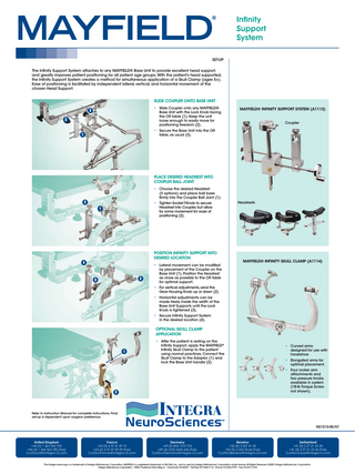
SET-UP The Infinity Support System attaches to any MAYFIELD® Base Unit to provide excellent head support, and greatly improves patient positioning for all patient age groups. With the patient’s head supported, the Infinity Support System creates a method for simultaneous application of a Skull Clamp (ages 5+). Ease of positioning is facilitated by independent lateral, vertical, and horizontal movement of the chosen Head Support.
Slide Coupler onto Base Unit • Slide Coupler onto any MAYFIELD®
2
Base Unit with the Lock Knob facing the OR table (1). Keep the unit loose enough to easily move for positioning freedom (2).
3
MAYFIELD® Infinity Support System (A1112) Coupler
• Secure the Base Unit into the OR
1
table, as usual (3).
Place Desired Headrest into Coupler Ball Joint • Choose the desired Headrest
(3 options) and place ball base firmly into the Coupler Ball Joint (1).
2
Headrests
• Tighten Socket T-Knob to secure
Headrest into Coupler, but allow for some movement for ease of positioning (2).
1
Position Infinity Support into Desired Location
4
• Lateral movement can be modified
2
3
MAYFIELD® Infinity Skull Clamp (A1114)
by placement of the Coupler on the Base Unit (1). Position the Headrest as close as possible to the OR table for optimal support.
• For vertical adjustments, wind the
Gear Housing Knob up or down (2).
• Horizontal adjustments can be
made freely inside the width of the Base Unit Supports until the Lock Knob is tightened (3).
• Secure Infinity Support System in the desired location (4).
OPTIONAL SKULL CLAMP APPLICATION • After the patient is resting on the
1
Infinity Support, apply the MAYFIELD® Infinity Skull Clamp to the patient using normal practices. Connect the Skull Clamp to the Adaptor (1) and lock the Base Unit handle (2).
• Curved arms
designed for use with horseshoe.
• Elongated arms for
optimal placement.
• Four rocker arm
attachments and two pressure knobs available in system (18-lb Torque Screw not shown).
2
Refer to Instruction Manual for complete instructions. Final set-up is dependent upon surgeon preference.
NS1515-08/07
United Kingdom
+44 (0) 1 264 345 700 +44 (0) 1 264 363 782 (Fax) [email protected]
France
+33 (0) 4 37 47 59 10 +33 (0) 4 37 47 59 29 (Fax) [email protected]
Germany
+49 (0) 800 1010 755 +49 (0) 2102 5536 636 (Fax) [email protected]
Benelux
+32 (0) 2 257 41 30 +32 (0) 2 253 24 66 (Fax) [email protected]
Switzerland
+41 (0) 2 27 21 23 30 +41 (0) 2 27 21 23 32 (Fax) [email protected]
The Integra wave logo is a trademark of Integra LifeSciences Corporation. MAYFIELD is a registered trademark of SM USA, Inc., and is used by Integra LifeSciences Corporation under license. All Rights Reserved. ©2007 Integra LifeSciences Corporation. Integra LifeSciences Corporation • 4900 Charlemar Drive, Bldg. A • Cincinnati, OH 45227 • Toll Free: 877-444-1114 • Phone: 513-533-7979 • Fax: 513-271-1915