Operating Manual
212 Pages

Preview
Page 1
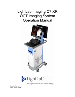
LightLab Imaging C7 XR OCT Imaging System Operation Manual
Operation Manual P/N 14296-01 Rev. B
Information provided within this document is subject to change without notice, and although believed to be accurate, LightLab Imaging assumes no responsibility for any errors, omissions, or inaccuracies. LightLab, LightLab Imaging Inc., C7 XR, C7 Dragonfly, and FD-OCT are trademarks of LightLab Imaging, Inc. All other trademarks are properties of their respective owners. This product is protected under one or more of the following U.S. and International patents: 5321501; 6134003; 6445939; 6891984; 7241286; EP 0581871; EP 0883793; EP 1222486; EP 1526800; JP 3479069; JP 3628026. Other U.S. and International patents pending. © Copyright 2009, 2010 by LightLab Imaging, Inc. All rights reserved. Reproduction, adaptation, or translation without prior permission is prohibited, except as allowed under copyright laws. MANUFACTURER LightLab Imaging, Inc., UK 1 Northumberland Avenue London WC2N 5BW United Kingdom MANUFACTURED AT LightLab Imaging, Inc. One Technology Park Drive Westford, MA 01886 USA
Phone: Fax: Email:
+44 20 7872 5708 +44 20 8938 6996 [email protected]
Phone: +1-978-692-1408 Fax: +1-978-692-1409 www.lightlabimaging.com
Service E-mail: [email protected] REVISION HISTORY September 25, 2009 14296-01
Rev. A
March 31, 2010
Rev. B
per ECO #646 R. Surko Initial release (SW version C.0.1) per ECO #802 R. Surko Revised for SW version C.0.2
Printed in the U.S.A. SAFETY INFORMATION Before using the C7 XR system, read this manual carefully, especially the safety information in Chapter 12 “Safety Information”. Pay special attention to the information marked with “Warning” and “Caution” text to the left of the text. Warnings alert the user to the possibility of injury, death or other serious adverse reactions. Cautions alert the user to possible problems with the product, including malfunctions, failures, and/or damage to the product or other property. WARNINGS Electrical Shock Hazard Do not remove C7 XR system covers. To avoid electrical shock, use only the power cord supplied with the system and connect only to properly grounded wall outlets. See Chapter 2 “System Setup” and Chapter 12 “Safety Information” for electrical safety information. Explosion Hazard Do not operate the C7 XR system in the presence of flammable anesthetics. Doing so could lead to an explosion. Visible and Invisible Laser Radiation Do not stare into the beam or view the beam directly with optical instruments. Doing so may cause serious eye damage and hazardous radiation exposure. WARNING SYMBOLS USED ON THE SYSTEM. Before using the C7 XR system, read this manual carefully, especially the identification of symbols used on the equipment and in this manual in Table 12-1 on page 12-2.
Contents Figures
Tables
Preface Using this Manual . . . . . . . . . . . . . . . . . . . . . . . . . . . . . . . . . . . . . . . . . . . . . . . . . .P-1 Conventions Used in this Manual . . . . . . . . . . . . . . . . . . . . . . . . . . . . . . . . . . . . . .P-1 Other Manuals . . . . . . . . . . . . . . . . . . . . . . . . . . . . . . . . . . . . . . . . . . . . . . . . . . . . .P-2
System Overview LightLab C7 XR OCT Imaging System Features . . . . . . . . . . . . . . . . . . . . . . . . . . 1-1 C7 XR Components . . . . . . . . . . . . . . . . . . . . . . . . . . . . . . . . . . . . . . . . . . . . . . . . . 1-2 The C7 XR Graphic Interface . . . . . . . . . . . . . . . . . . . . . . . . . . . . . . . . . . . . . . . . . 1-6 The Drive-motor and Optical Controller (DOC) . . . . . . . . . . . . . . . . . . . . . . . . . . . 1-8 Start and Stop Pullback with Recording. . . . . . . . . . . . . . . . . . . . . . . . . . . . . 1-9 Immediately Stop Operation . . . . . . . . . . . . . . . . . . . . . . . . . . . . . . . . . . . . . 1-9 Intended Use and Indications for Use . . . . . . . . . . . . . . . . . . . . . . . . . . . . . . . . . . . 1-9
System Setup Positioning your System . . . . . . . . . . . . . . . . . . . . . . . . . . . . . . . . . . . . . . . . . . . . . 2-1 Connecting Your System . . . . . . . . . . . . . . . . . . . . . . . . . . . . . . . . . . . . . . . . . . . . . 2-2 System Connections . . . . . . . . . . . . . . . . . . . . . . . . . . . . . . . . . . . . . . . . . . . . 2-2 C7 XR OCT Imaging System Operation Manual
i
Contents
Powering On and Shutting Down Your System . . . . . . . . . . . . . . . . . . . . . . . . . . . 2-2 Power On . . . . . . . . . . . . . . . . . . . . . . . . . . . . . . . . . . . . . . . . . . . . . . . . . . . . 2-2 Shut Down . . . . . . . . . . . . . . . . . . . . . . . . . . . . . . . . . . . . . . . . . . . . . . . . . . . 2-3 Configuring the C7 XR OCT Imaging System . . . . . . . . . . . . . . . . . . . . . . . . . . . . 2-3 Enter Configuration . . . . . . . . . . . . . . . . . . . . . . . . . . . . . . . . . . . . . . . . . . . . 2-4 Set the Current Date and Time . . . . . . . . . . . . . . . . . . . . . . . . . . . . . . . . . . . . 2-5 Restore Factory Defaults . . . . . . . . . . . . . . . . . . . . . . . . . . . . . . . . . . . . . . . . 2-5 Set Institution Name. . . . . . . . . . . . . . . . . . . . . . . . . . . . . . . . . . . . . . . . . . . . 2-6 Set Catheter Type . . . . . . . . . . . . . . . . . . . . . . . . . . . . . . . . . . . . . . . . . . . . . . 2-6 Automatically Review Recordings. . . . . . . . . . . . . . . . . . . . . . . . . . . . . . . . . 2-6 Set Pullback and Advance Options . . . . . . . . . . . . . . . . . . . . . . . . . . . . . . . . 2-7 Approve or Cancel Configuration Changes . . . . . . . . . . . . . . . . . . . . . . . . . . 2-7 Configuring DICOM Network Settings. . . . . . . . . . . . . . . . . . . . . . . . . . . . . . . . . . 2-7 Setting up the Image . . . . . . . . . . . . . . . . . . . . . . . . . . . . . . . . . . . . . . . . . . . . . . . . 2-8 Set Playback Settings . . . . . . . . . . . . . . . . . . . . . . . . . . . . . . . . . . . . . . . . . . . 2-9 Set Presentation Settings . . . . . . . . . . . . . . . . . . . . . . . . . . . . . . . . . . . . . . . . 2-10 Monitor Setup . . . . . . . . . . . . . . . . . . . . . . . . . . . . . . . . . . . . . . . . . . . . . . . . . . . . . 2-14 Setting Monitor Functions . . . . . . . . . . . . . . . . . . . . . . . . . . . . . . . . . . . . . . . 2-14 Setting Monitor Position . . . . . . . . . . . . . . . . . . . . . . . . . . . . . . . . . . . . . . . . 2-14 Using an External Monitor . . . . . . . . . . . . . . . . . . . . . . . . . . . . . . . . . . . . . . . 2-14
Starting an Exam Startup . . . . . . . . . . . . . . . . . . . . . . . . . . . . . . . . . . . . . . . . . . . . . . . . . . . . . . . . . . . 3-1 Assigning a Case to a Patient. . . . . . . . . . . . . . . . . . . . . . . . . . . . . . . . . . . . . . . . . . 3-2 Opening a Patient Case. . . . . . . . . . . . . . . . . . . . . . . . . . . . . . . . . . . . . . . . . . 3-2 Open an Existing Case . . . . . . . . . . . . . . . . . . . . . . . . . . . . . . . . . . . . . . . . . . 3-3 Create a New Case . . . . . . . . . . . . . . . . . . . . . . . . . . . . . . . . . . . . . . . . . . . . . 3-4 Default Patient Warning Messages . . . . . . . . . . . . . . . . . . . . . . . . . . . . . . . . 3-5 Edit/Enter Patient Information . . . . . . . . . . . . . . . . . . . . . . . . . . . . . . . . . . . . 3-5 Attach the Catheter to the DOC. . . . . . . . . . . . . . . . . . . . . . . . . . . . . . . . . . . . . . . . 3-6 Auto Z Offset Calibration. . . . . . . . . . . . . . . . . . . . . . . . . . . . . . . . . . . . . . . . 3-7 Setting the Z Offset . . . . . . . . . . . . . . . . . . . . . . . . . . . . . . . . . . . . . . . . . . . . 3-7 Setting the Flush Medium . . . . . . . . . . . . . . . . . . . . . . . . . . . . . . . . . . . . . . . . . . . . 3-10 Contrast Only Option . . . . . . . . . . . . . . . . . . . . . . . . . . . . . . . . . . . . . . . . . . . 3-10 Confirm Flush Medium . . . . . . . . . . . . . . . . . . . . . . . . . . . . . . . . . . . . . . . . . 3-10 Pressure Transducer Connection . . . . . . . . . . . . . . . . . . . . . . . . . . . . . . . . . . . . . . . 3-10 Acquiring a Test Image . . . . . . . . . . . . . . . . . . . . . . . . . . . . . . . . . . . . . . . . . . . . . . 3-11 Calibrating the C7 Dragonfly Catheter . . . . . . . . . . . . . . . . . . . . . . . . . . . . . 3-12
ii
LightLab Imaging, Inc. P/N 14296-01 Rev. B
Contents
Acquiring a Patient Image . . . . . . . . . . . . . . . . . . . . . . . . . . . . . . . . . . . . . . . . . . . . 3-13 Catheter Failure . . . . . . . . . . . . . . . . . . . . . . . . . . . . . . . . . . . . . . . . . . . . . . . . . . . . 3-14
Acquiring, Recording, and Saving Images Operating Modes . . . . . . . . . . . . . . . . . . . . . . . . . . . . . . . . . . . . . . . . . . . . . . . . . . . 4-1 Live Mode . . . . . . . . . . . . . . . . . . . . . . . . . . . . . . . . . . . . . . . . . . . . . . . . . . . 4-1 Playback Mode . . . . . . . . . . . . . . . . . . . . . . . . . . . . . . . . . . . . . . . . . . . . . . . . 4-3 Acquiring and Recording Images . . . . . . . . . . . . . . . . . . . . . . . . . . . . . . . . . . . . . . 4-3 Automatic Limits . . . . . . . . . . . . . . . . . . . . . . . . . . . . . . . . . . . . . . . . . . . . . . 4-3 Beginning to Image . . . . . . . . . . . . . . . . . . . . . . . . . . . . . . . . . . . . . . . . . . . . 4-3 The System Display - Image Acquisition . . . . . . . . . . . . . . . . . . . . . . . . . . . . . . . . 4-4 Recording Images with Automatic Pullback . . . . . . . . . . . . . . . . . . . . . . . . . . . . . . 4-5 The Advance Optical Fiber Control . . . . . . . . . . . . . . . . . . . . . . . . . . . . . . . . 4-6 Setting up Default Comments . . . . . . . . . . . . . . . . . . . . . . . . . . . . . . . . . . . . . . . . . 4-7 Saving Still Images . . . . . . . . . . . . . . . . . . . . . . . . . . . . . . . . . . . . . . . . . . . . . . . . . 4-8 Save a Still Image. . . . . . . . . . . . . . . . . . . . . . . . . . . . . . . . . . . . . . . . . . . . . . 4-8 Image Display Controls . . . . . . . . . . . . . . . . . . . . . . . . . . . . . . . . . . . . . . . . . . . . . . 4-8 Z Offset. . . . . . . . . . . . . . . . . . . . . . . . . . . . . . . . . . . . . . . . . . . . . . . . . . . . . . 4-9 Full Screen/Exit Full Screen. . . . . . . . . . . . . . . . . . . . . . . . . . . . . . . . . . . . . . 4-9
Reviewing Images Reviewing a Saved Image for the Current Patient. . . . . . . . . . . . . . . . . . . . . . . . . . 5-1 Reviewing a Saved Image from a Previous Patient. . . . . . . . . . . . . . . . . . . . . . . . . 5-2 Playback Mode . . . . . . . . . . . . . . . . . . . . . . . . . . . . . . . . . . . . . . . . . . . . . . . . 5-2 The Review Controls . . . . . . . . . . . . . . . . . . . . . . . . . . . . . . . . . . . . . . . . . . . 5-4 Playback and Presentation Settings in the Settings Tab . . . . . . . . . . . . . . . . . . . . . 5-5 Reviewing a Recording . . . . . . . . . . . . . . . . . . . . . . . . . . . . . . . . . . . . . . . . . . . . . . 5-6 Editing a Recording . . . . . . . . . . . . . . . . . . . . . . . . . . . . . . . . . . . . . . . . . . . . . . . . . 5-6 Editing a Comment . . . . . . . . . . . . . . . . . . . . . . . . . . . . . . . . . . . . . . . . . . . . . . . . . 5-7 Editing by Single-clicking the Image. . . . . . . . . . . . . . . . . . . . . . . . . . . . . . . 5-7 Editing by Using the Shortcut Menu . . . . . . . . . . . . . . . . . . . . . . . . . . . . . . . 5-7 Softkeys Available During Review . . . . . . . . . . . . . . . . . . . . . . . . . . . . . . . . . . . . . 5-8 Setting Z Offset in Playback Mode . . . . . . . . . . . . . . . . . . . . . . . . . . . . . . . . . . . . . 5-8 About Segments . . . . . . . . . . . . . . . . . . . . . . . . . . . . . . . . . . . . . . . . . . . . . . . 5-9 C7 XR OCT Imaging System Operation Manual
iii
Contents
Setting the Z Offset . . . . . . . . . . . . . . . . . . . . . . . . . . . . . . . . . . . . . . . . . . . . 5-9 Resetting the Z Offset. . . . . . . . . . . . . . . . . . . . . . . . . . . . . . . . . . . . . . . . . . . 5-10 Zooming Regions of Interest . . . . . . . . . . . . . . . . . . . . . . . . . . . . . . . . . . . . . . . . . . 5-11 Basic Zoom. . . . . . . . . . . . . . . . . . . . . . . . . . . . . . . . . . . . . . . . . . . . . . . . . . . 5-12 Zoom Function . . . . . . . . . . . . . . . . . . . . . . . . . . . . . . . . . . . . . . . . . . . . . . . . 5-12
L-Mode Imaging The L-Mode View . . . . . . . . . . . . . . . . . . . . . . . . . . . . . . . . . . . . . . . . . . . . . . . . . . 6-2 L-Mode Acquisition. . . . . . . . . . . . . . . . . . . . . . . . . . . . . . . . . . . . . . . . . . . . . . . . . 6-2 Changing the Displayed Cut-plane(s) . . . . . . . . . . . . . . . . . . . . . . . . . . . . . . . . . . . 6-3 Reviewing L-Mode Data . . . . . . . . . . . . . . . . . . . . . . . . . . . . . . . . . . . . . . . . . . . . . 6-3 Displaying an Image with L-Mode Data . . . . . . . . . . . . . . . . . . . . . . . . . . . . . . . . . 6-4 Zooming the L-Mode View . . . . . . . . . . . . . . . . . . . . . . . . . . . . . . . . . . . . . . 6-5 Selecting a New L-Mode Cut-plane During Review . . . . . . . . . . . . . . . . . . . 6-5 Turning Off the L-Mode View. . . . . . . . . . . . . . . . . . . . . . . . . . . . . . . . . . . . 6-5 Measurements and Annotations in the L-Mode View . . . . . . . . . . . . . . . . . . 6-5 Limitations of L-Mode Data. . . . . . . . . . . . . . . . . . . . . . . . . . . . . . . . . . . . . . 6-5
Text Annotation Displaying the Text Annotation Tools. . . . . . . . . . . . . . . . . . . . . . . . . . . . . . . . . . . 7-1 Adding Annotations. . . . . . . . . . . . . . . . . . . . . . . . . . . . . . . . . . . . . . . . . . . . . . . . . 7-3 To Add a Marker to an Image . . . . . . . . . . . . . . . . . . . . . . . . . . . . . . . . . . . . 7-4 To Add Text to an Image . . . . . . . . . . . . . . . . . . . . . . . . . . . . . . . . . . . . . . . . 7-4 Hiding Annotations and Measurements. . . . . . . . . . . . . . . . . . . . . . . . . . . . . . . . . . 7-6 Locating Annotations and Measurements . . . . . . . . . . . . . . . . . . . . . . . . . . . . . . . . 7-6 Editing and Moving Annotations. . . . . . . . . . . . . . . . . . . . . . . . . . . . . . . . . . . . . . . 7-7 Move a Text Annotation or Marker . . . . . . . . . . . . . . . . . . . . . . . . . . . . . . . . 7-7 Edit a Text Annotation . . . . . . . . . . . . . . . . . . . . . . . . . . . . . . . . . . . . . . . . . . 7-7 Change the Display Setting for a Marker on a Recording . . . . . . . . . . . . . . . 7-7 Deleting Annotations . . . . . . . . . . . . . . . . . . . . . . . . . . . . . . . . . . . . . . . . . . . 7-8 Bookmarking Frames in a Recording . . . . . . . . . . . . . . . . . . . . . . . . . . . . . . . . . . . 7-9
Measurements & Calculations Measurements and Calculations in the Image Files. . . . . . . . . . . . . . . . . . . . . . . . . 8-1
iv
LightLab Imaging, Inc. P/N 14296-01 Rev. B
Contents
Measurement and Calculations Tools . . . . . . . . . . . . . . . . . . . . . . . . . . . . . . . . . . . 8-2 Techniques to Improve Measurement Accuracy . . . . . . . . . . . . . . . . . . . . . . . . . . . 8-3 Length Measurements . . . . . . . . . . . . . . . . . . . . . . . . . . . . . . . . . . . . . . . . . . . . . . . 8-4 Make a Length (Distance) Measurement . . . . . . . . . . . . . . . . . . . . . . . . . . . . 8-4 Areas . . . . . . . . . . . . . . . . . . . . . . . . . . . . . . . . . . . . . . . . . . . . . . . . . . . . . . . . . . . . 8-5 Freehand Trace Area Measurements . . . . . . . . . . . . . . . . . . . . . . . . . . . . . . . . . . . . 8-5 Make a Freehand Trace Area Measurement. . . . . . . . . . . . . . . . . . . . . . . . . . 8-6 Multiple Point Area Measurements . . . . . . . . . . . . . . . . . . . . . . . . . . . . . . . . . . . . . 8-7 Make a Multiple Point Area Measurement . . . . . . . . . . . . . . . . . . . . . . . . . . 8-8 Automatic Area Measurements . . . . . . . . . . . . . . . . . . . . . . . . . . . . . . . . . . . . . . . . 8-9 Make an Automatic Area Measurement. . . . . . . . . . . . . . . . . . . . . . . . . . . . . 8-10 The %AS Calculation . . . . . . . . . . . . . . . . . . . . . . . . . . . . . . . . . . . . . . . . . . . . . . . 8-11 Formula for %AS Calculation . . . . . . . . . . . . . . . . . . . . . . . . . . . . . . . . . . . . 8-11 Make a %AS Calculation . . . . . . . . . . . . . . . . . . . . . . . . . . . . . . . . . . . . . . . . 8-11 The %DS Calculation . . . . . . . . . . . . . . . . . . . . . . . . . . . . . . . . . . . . . . . . . . . . . . . 8-14 Formula for %DS Calculation . . . . . . . . . . . . . . . . . . . . . . . . . . . . . . . . . . . . 8-14 Make a %DS Calculation . . . . . . . . . . . . . . . . . . . . . . . . . . . . . . . . . . . . . . . . 8-14 Diameter Measurement . . . . . . . . . . . . . . . . . . . . . . . . . . . . . . . . . . . . . . . . . . . . . . 8-15 The Diameter Calculation . . . . . . . . . . . . . . . . . . . . . . . . . . . . . . . . . . . . . . . 8-16 Make a Diameter Calculation. . . . . . . . . . . . . . . . . . . . . . . . . . . . . . . . . . . . . 8-16 Editing Measurements . . . . . . . . . . . . . . . . . . . . . . . . . . . . . . . . . . . . . . . . . . . . . . . 8-17 Locking/Unlocking Measurements . . . . . . . . . . . . . . . . . . . . . . . . . . . . . . . . 8-17 Moving Individual Points. . . . . . . . . . . . . . . . . . . . . . . . . . . . . . . . . . . . . . . . 8-18 Add Points to a Multiple Point Area . . . . . . . . . . . . . . . . . . . . . . . . . . . . . . . 8-18 Delete Points from a Multiple Point Area . . . . . . . . . . . . . . . . . . . . . . . . . . . 8-19 Delete Multiple Points from an Area . . . . . . . . . . . . . . . . . . . . . . . . . . . . . . . 8-19 Delete Measurements . . . . . . . . . . . . . . . . . . . . . . . . . . . . . . . . . . . . . . . . . . . 8-19 Additional Measurement Tools . . . . . . . . . . . . . . . . . . . . . . . . . . . . . . . . . . . . . . . . 8-19 Setting Pen Color, Line Width, and Point Size . . . . . . . . . . . . . . . . . . . . . . . . . . . . 8-20 Set Measurement Attributes . . . . . . . . . . . . . . . . . . . . . . . . . . . . . . . . . . . . . . 8-20 Setting Color Autocycling . . . . . . . . . . . . . . . . . . . . . . . . . . . . . . . . . . . . . . . . . . . . 8-21 Turn Auto Cycle Drawing Color On and Off. . . . . . . . . . . . . . . . . . . . . . . . . 8-21 Hiding Measurements . . . . . . . . . . . . . . . . . . . . . . . . . . . . . . . . . . . . . . . . . . . . . . . 8-21 Finding Measurements in a Recording . . . . . . . . . . . . . . . . . . . . . . . . . . . . . . . . . . 8-21
C7 XR OCT Imaging System Operation Manual
v
Contents
Exporting, Importing, and Managing Files Compatible Transfer Media and USB Devices . . . . . . . . . . . . . . . . . . . . . . . . . . . . 9-1 Optical Media . . . . . . . . . . . . . . . . . . . . . . . . . . . . . . . . . . . . . . . . . . . . . . . . . 9-1 USB Connected Media. . . . . . . . . . . . . . . . . . . . . . . . . . . . . . . . . . . . . . . . . . 9-3 File Formats . . . . . . . . . . . . . . . . . . . . . . . . . . . . . . . . . . . . . . . . . . . . . . . . . . . . . . . 9-3 About Raw (OCT) Format . . . . . . . . . . . . . . . . . . . . . . . . . . . . . . . . . . . . . . . 9-4 About Standard Format . . . . . . . . . . . . . . . . . . . . . . . . . . . . . . . . . . . . . . . . . 9-4 Image Format and Size in Standard Formats. . . . . . . . . . . . . . . . . . . . . . . . . . . . . . 9-4 File Size . . . . . . . . . . . . . . . . . . . . . . . . . . . . . . . . . . . . . . . . . . . . . . . . . . . . . 9-5 Standard File Formats . . . . . . . . . . . . . . . . . . . . . . . . . . . . . . . . . . . . . . . . . . 9-5 Exporting and Transferring During Review . . . . . . . . . . . . . . . . . . . . . . . . . . . . . . 9-6 Exporting a Single File . . . . . . . . . . . . . . . . . . . . . . . . . . . . . . . . . . . . . . . . . . . . . . 9-7 Exporting Multiple Files . . . . . . . . . . . . . . . . . . . . . . . . . . . . . . . . . . . . . . . . . . . . . 9-10 Export Multiple Files from the Images Tab . . . . . . . . . . . . . . . . . . . . . . . . . . 9-10 Exporting Raw Format Files From the Database Tab . . . . . . . . . . . . . . . . . . . . . . . 9-16 To Export Multiple Raw Files from the Database Tab . . . . . . . . . . . . . . . . . 9-16 Using Exported Standard Format Recordings . . . . . . . . . . . . . . . . . . . . . . . . . . . . . 9-17 LightLab DICOM Viewer . . . . . . . . . . . . . . . . . . . . . . . . . . . . . . . . . . . . . . . 9-18 Importing OCT files. . . . . . . . . . . . . . . . . . . . . . . . . . . . . . . . . . . . . . . . . . . . . . . . . 9-22 To Import OCT Image Files from a CD/DVD . . . . . . . . . . . . . . . . . . . . . . . . 9-24 Importing Patient Information from a Remote DICOM Server . . . . . . . . . . . . . . . 9-25 Managing Files . . . . . . . . . . . . . . . . . . . . . . . . . . . . . . . . . . . . . . . . . . . . . . . . . . . . 9-27 Transferring Exported Files to a CD/DVD or USB Device. . . . . . . . . . . . . . 9-27 Deleting OCT Image Files . . . . . . . . . . . . . . . . . . . . . . . . . . . . . . . . . . . . . . . 9-29 Deleting Exported Files from the Hard Drive . . . . . . . . . . . . . . . . . . . . . . . . 9-29 Transfer and Import Messages. . . . . . . . . . . . . . . . . . . . . . . . . . . . . . . . . . . . . . . . . 9-31 Database Statistics . . . . . . . . . . . . . . . . . . . . . . . . . . . . . . . . . . . . . . . . . . . . . . . . . . 9-33 Duplicate File Name Messages . . . . . . . . . . . . . . . . . . . . . . . . . . . . . . . . . . . . . . . . 9-34
Cleaning & Maintenance Contacting LightLab Service . . . . . . . . . . . . . . . . . . . . . . . . . . . . . . . . . . . . . . . . . 10-1 Cleaning . . . . . . . . . . . . . . . . . . . . . . . . . . . . . . . . . . . . . . . . . . . . . . . . . . . . . . . . . 10-2 Routine Cleaning Procedure. . . . . . . . . . . . . . . . . . . . . . . . . . . . . . . . . . . . . 10-2 Maintenance. . . . . . . . . . . . . . . . . . . . . . . . . . . . . . . . . . . . . . . . . . . . . . . . . . . . . . 10-3 Optical Connection Cleaning Procedure . . . . . . . . . . . . . . . . . . . . . . . . . . . 10-3
vi
LightLab Imaging, Inc. P/N 14296-01 Rev. B
Contents
Optical Adapter Replacement Procedure . . . . . . . . . . . . . . . . . . . . . . . . . . . 10-5 C7 XR Air Filter Maintenance Procedure . . . . . . . . . . . . . . . . . . . . . . . . . . 10-7 Cable Connection Inspection Procedure . . . . . . . . . . . . . . . . . . . . . . . . . . . 10-8 Transferring Log Files . . . . . . . . . . . . . . . . . . . . . . . . . . . . . . . . . . . . . . . . . 10-8 Identifying Software Version . . . . . . . . . . . . . . . . . . . . . . . . . . . . . . . . . . . . 10-10 Infection Control . . . . . . . . . . . . . . . . . . . . . . . . . . . . . . . . . . . . . . . . . . . . . . . . . . 10-10 User Troubleshooting . . . . . . . . . . . . . . . . . . . . . . . . . . . . . . . . . . . . . . . . . . . . . . 10-11
User Interface Reference The User Interface . . . . . . . . . . . . . . . . . . . . . . . . . . . . . . . . . . . . . . . . . . . . . . . . . 11-1 The Image Management Area . . . . . . . . . . . . . . . . . . . . . . . . . . . . . . . . . . . . . . . . 11-2 The Images Tab . . . . . . . . . . . . . . . . . . . . . . . . . . . . . . . . . . . . . . . . . . . . . . 11-2 The Settings Tab. . . . . . . . . . . . . . . . . . . . . . . . . . . . . . . . . . . . . . . . . . . . . . 11-3 The Setup Dialog Box . . . . . . . . . . . . . . . . . . . . . . . . . . . . . . . . . . . . . . . . . . . . . . 11-5 The Configure Tab . . . . . . . . . . . . . . . . . . . . . . . . . . . . . . . . . . . . . . . . . . . . 11-6 The Database Tab. . . . . . . . . . . . . . . . . . . . . . . . . . . . . . . . . . . . . . . . . . . . . 11-9 The Measurements Tab . . . . . . . . . . . . . . . . . . . . . . . . . . . . . . . . . . . . . . . . 11-11 The Diagnostics Tab. . . . . . . . . . . . . . . . . . . . . . . . . . . . . . . . . . . . . . . . . . . 11-12 The Options Tab. . . . . . . . . . . . . . . . . . . . . . . . . . . . . . . . . . . . . . . . . . . . . . 11-14 The Usage Tab . . . . . . . . . . . . . . . . . . . . . . . . . . . . . . . . . . . . . . . . . . . . . . . 11-15 The DICOM Tab . . . . . . . . . . . . . . . . . . . . . . . . . . . . . . . . . . . . . . . . . . . . . 11-17 The Service Tab . . . . . . . . . . . . . . . . . . . . . . . . . . . . . . . . . . . . . . . . . . . . . . 11-20
Safety Information Symbols Used on the System. . . . . . . . . . . . . . . . . . . . . . . . . . . . . . . . . . . . . . . . . 12-2 Patient Safety . . . . . . . . . . . . . . . . . . . . . . . . . . . . . . . . . . . . . . . . . . . . . . . . . . . . . 12-2 General . . . . . . . . . . . . . . . . . . . . . . . . . . . . . . . . . . . . . . . . . . . . . . . . . . . . . 12-2 Techniques to Minimize Patient Exposure. . . . . . . . . . . . . . . . . . . . . . . . . . 12-3 Operator Safety . . . . . . . . . . . . . . . . . . . . . . . . . . . . . . . . . . . . . . . . . . . . . . . . . . . 12-3 Avoiding Operator Light Emission Hazards . . . . . . . . . . . . . . . . . . . . . . . . 12-3 Repetitive Strain Injury (RSI) . . . . . . . . . . . . . . . . . . . . . . . . . . . . . . . . . . . 12-4 Moving the System . . . . . . . . . . . . . . . . . . . . . . . . . . . . . . . . . . . . . . . . . . . . . . . . 12-4 Positioning the System. . . . . . . . . . . . . . . . . . . . . . . . . . . . . . . . . . . . . . . . . . . . . . 12-5 Avoiding Electrical Hazards . . . . . . . . . . . . . . . . . . . . . . . . . . . . . . . . . . . . . . . . . 12-6 Making Proper Electrical Connections . . . . . . . . . . . . . . . . . . . . . . . . . . . . . . . . . 12-7 Explosion Hazard. . . . . . . . . . . . . . . . . . . . . . . . . . . . . . . . . . . . . . . . . . . . . . . . . . 12-7 C7 XR OCT Imaging System Operation Manual
vii
Contents
System Specifications System - Safety & Regulatory . . . . . . . . . . . . . . . . . . . . . . . . . . . . . . . . . . . . . . . . 13-2 System - Electrical and Physical . . . . . . . . . . . . . . . . . . . . . . . . . . . . . . . . . . . . . . 13-4 Imaging . . . . . . . . . . . . . . . . . . . . . . . . . . . . . . . . . . . . . . . . . . . . . . . . . . . . . . . . . 13-4 Electromagnetic Emissions . . . . . . . . . . . . . . . . . . . . . . . . . . . . . . . . . . . . . . . . . . 13-5
Index
viii
LightLab Imaging, Inc. P/N 14296-01 Rev. B
Figures
Figures 1-1 1-2 1-3 1-4 1-5
C7 XR OCT System - Physician Side . . . . . . . . . . . . . . . . . . . . . . . . . . . . . . 1-3 C7 XR OCT System - Operator Side . . . . . . . . . . . . . . . . . . . . . . . . . . . . . . . 1-4 C7 XR OCT System Connector Panel . . . . . . . . . . . . . . . . . . . . . . . . . . . . . . 1-5 C7 XR OCT Imaging System Display . . . . . . . . . . . . . . . . . . . . . . . . . . . . . . 1-6 Drive-motor and Optical Controller (DOC). . . . . . . . . . . . . . . . . . . . . . . . . . 1-8
2-1 2-2 2-3 2-4 2-5 2-6 2-7 2-8 2-9 2-10
C7 XR Connections . . . . . . . . . . . . . . . . . . . . . . . . . . . . . . . . . . . . . . . . . . . . 2-2 Shutdown Dialog Box . . . . . . . . . . . . . . . . . . . . . . . . . . . . . . . . . . . . . . . . . . 2-3 The Configure Tab in the Setup Dialog Box . . . . . . . . . . . . . . . . . . . . . . . . . 2-4 The Date and Time Properties Dialog Box . . . . . . . . . . . . . . . . . . . . . . . . . . 2-5 The Settings Tab in the Image Management Area . . . . . . . . . . . . . . . . . . . . . 2-9 Color Map Menu . . . . . . . . . . . . . . . . . . . . . . . . . . . . . . . . . . . . . . . . . . . . . . 2-11 Tick Style Menu . . . . . . . . . . . . . . . . . . . . . . . . . . . . . . . . . . . . . . . . . . . . . . . 2-11 Tick Styles . . . . . . . . . . . . . . . . . . . . . . . . . . . . . . . . . . . . . . . . . . . . . . . . . . . 2-12 Range Menu . . . . . . . . . . . . . . . . . . . . . . . . . . . . . . . . . . . . . . . . . . . . . . . . . . 2-13 L-Mode Smoothing Menu . . . . . . . . . . . . . . . . . . . . . . . . . . . . . . . . . . . . . . . 2-13
3-1 3-2 3-3 3-4 3-5 3-6 3-7 3-8 3-9 3-10 3-11 3-12 3-13 3-14 3-15 3-16 3-17 3-18
Open/Create Case Dialog Box . . . . . . . . . . . . . . . . . . . . . . . . . . . . . . . . . . . . 3-2 Patient Information Dialog Box . . . . . . . . . . . . . . . . . . . . . . . . . . . . . . . . . . . 3-2 Open an Existing Case Dialog Box . . . . . . . . . . . . . . . . . . . . . . . . . . . . . . . . 3-3 Create a New Case Dialog Box . . . . . . . . . . . . . . . . . . . . . . . . . . . . . . . . . . . 3-4 Default Patient Selected Warning Message . . . . . . . . . . . . . . . . . . . . . . . . . . 3-5 Using Default Patient Warning Message . . . . . . . . . . . . . . . . . . . . . . . . . . . . 3-5 Edit/Enter Patient Information Dialog Box . . . . . . . . . . . . . . . . . . . . . . . . . . 3-6 Auto Z Calibration Succeeded . . . . . . . . . . . . . . . . . . . . . . . . . . . . . . . . . . . . 3-7 Auto Z Calibration Failed. . . . . . . . . . . . . . . . . . . . . . . . . . . . . . . . . . . . . . . . 3-7 Setting Z Offset . . . . . . . . . . . . . . . . . . . . . . . . . . . . . . . . . . . . . . . . . . . . . . . 3-8 The Z Offset After System Initiated Calibration . . . . . . . . . . . . . . . . . . . . . . 3-9 Final Catheter Position Examples . . . . . . . . . . . . . . . . . . . . . . . . . . . . . . . . . 3-9 Confirm Flush Medium Dialog Box . . . . . . . . . . . . . . . . . . . . . . . . . . . . . . . 3-10 Flush Medium Selection Box . . . . . . . . . . . . . . . . . . . . . . . . . . . . . . . . . . . . . 3-10 Pressure Transducer Connected Icon . . . . . . . . . . . . . . . . . . . . . . . . . . . . . . . 3-11 Properly Calibrated Test Image . . . . . . . . . . . . . . . . . . . . . . . . . . . . . . . . . . . 3-12 Catheter Failure Message . . . . . . . . . . . . . . . . . . . . . . . . . . . . . . . . . . . . . . . . 3-14 Replace Catheter Message . . . . . . . . . . . . . . . . . . . . . . . . . . . . . . . . . . . . . . . 3-14
C7 XR OCT Imaging System Operation Manual
ix
Figures
x
4-1 4-2
System Display Format - Acquisition . . . . . . . . . . . . . . . . . . . . . . . . . . . . . . 4-4 The Comment Drop-Down Menu . . . . . . . . . . . . . . . . . . . . . . . . . . . . . . . . . 4-7
5-1 5-2 5-3 5-4 5-5 5-6 5-7 5-8 5-9
System Display Format - Playback . . . . . . . . . . . . . . . . . . . . . . . . . . . . . . . . 5-3 Review Controls and Timeline for Recordings . . . . . . . . . . . . . . . . . . . . . . . 5-4 Review Controls for Still Images . . . . . . . . . . . . . . . . . . . . . . . . . . . . . . . . . . 5-4 Editing a Comment. . . . . . . . . . . . . . . . . . . . . . . . . . . . . . . . . . . . . . . . . . . . . 5-7 Image Shortcut Menu . . . . . . . . . . . . . . . . . . . . . . . . . . . . . . . . . . . . . . . . . . . 5-8 Effects of Z Offset Changes in Playback . . . . . . . . . . . . . . . . . . . . . . . . . . . . 5-9 Z Offset Dialog Box in Playback . . . . . . . . . . . . . . . . . . . . . . . . . . . . . . . . . . 5-10 Z Offset Reset Buttons . . . . . . . . . . . . . . . . . . . . . . . . . . . . . . . . . . . . . . . . . . 5-11 Zooming an Image . . . . . . . . . . . . . . . . . . . . . . . . . . . . . . . . . . . . . . . . . . . . . 5-12
6-1 6-2
L-Mode Format (Single Trace Shown) . . . . . . . . . . . . . . . . . . . . . . . . . . . . . 6-2 L-Mode Review Format (Dual Trace Shown) . . . . . . . . . . . . . . . . . . . . . . . . 6-4
7-1 7-2 7-3 7-4 7-5 7-6 7-7 7-8 7-9
Annotation Shortcut Menu . . . . . . . . . . . . . . . . . . . . . . . . . . . . . . . . . . . . . . . 7-2 Selected Marker and Text Annotations . . . . . . . . . . . . . . . . . . . . . . . . . . . . . 7-3 Marker Dialog Box. . . . . . . . . . . . . . . . . . . . . . . . . . . . . . . . . . . . . . . . . . . . . 7-4 Text Entry Dialog Box . . . . . . . . . . . . . . . . . . . . . . . . . . . . . . . . . . . . . . . . . . 7-5 Font Dialog Box . . . . . . . . . . . . . . . . . . . . . . . . . . . . . . . . . . . . . . . . . . . . . . . 7-5 Delete Annotations Menu. . . . . . . . . . . . . . . . . . . . . . . . . . . . . . . . . . . . . . . . 7-8 Delete Confirmation Alert . . . . . . . . . . . . . . . . . . . . . . . . . . . . . . . . . . . . . . . 7-8 Bookmark Menu. . . . . . . . . . . . . . . . . . . . . . . . . . . . . . . . . . . . . . . . . . . . . . . 7-9 Bookmarked Frame Indicator. . . . . . . . . . . . . . . . . . . . . . . . . . . . . . . . . . . . . 7-9
8-1 8-2 8-3 8-4 8-5 8-6 8-7 8-8 8-9 8-10 8-11 8-12 8-13 8-14
Measurement Menu . . . . . . . . . . . . . . . . . . . . . . . . . . . . . . . . . . . . . . . . . . . . 8-2 Length Measurement (Zoomed). . . . . . . . . . . . . . . . . . . . . . . . . . . . . . . . . . . 8-4 Freehand Trace Area Measurements . . . . . . . . . . . . . . . . . . . . . . . . . . . . . . . 8-6 In Process Multiple Point Area Trace . . . . . . . . . . . . . . . . . . . . . . . . . . . . . . 8-8 Automatic Area Measurement In Process . . . . . . . . . . . . . . . . . . . . . . . . . . . 8-10 Contour Not Detected Dialog Box . . . . . . . . . . . . . . . . . . . . . . . . . . . . . . . . . 8-11 %AS Area Measurements Dialog Box. . . . . . . . . . . . . . . . . . . . . . . . . . . . . . 8-12 %AS Calculation . . . . . . . . . . . . . . . . . . . . . . . . . . . . . . . . . . . . . . . . . . . . . . 8-13 %AS Error Message . . . . . . . . . . . . . . . . . . . . . . . . . . . . . . . . . . . . . . . . . . . . 8-13 %DS Diameter Measurement Dialog Box . . . . . . . . . . . . . . . . . . . . . . . . . . . 8-14 %DS Calculation . . . . . . . . . . . . . . . . . . . . . . . . . . . . . . . . . . . . . . . . . . . . . . 8-15 Diameter Measurement . . . . . . . . . . . . . . . . . . . . . . . . . . . . . . . . . . . . . . . . . 8-16 Select Measurement Dialog Box . . . . . . . . . . . . . . . . . . . . . . . . . . . . . . . . . . 8-17 Measurement Tools Shortcut Menu . . . . . . . . . . . . . . . . . . . . . . . . . . . . . . . . 8-20
9-1 9-2 9-3 9-4
Erase Media Contents Prompt . . . . . . . . . . . . . . . . . . . . . . . . . . . . . . . . . . . . 9-2 Erase Media Contents Verification . . . . . . . . . . . . . . . . . . . . . . . . . . . . . . . . 9-2 Disc Full Warning Message . . . . . . . . . . . . . . . . . . . . . . . . . . . . . . . . . . . . . . 9-3 The Export Current Image File Dialog Box. . . . . . . . . . . . . . . . . . . . . . . . . . 9-7 LightLab Imaging, Inc. P/N 14296-01 Rev. B
Figures
9-5 9-6 9-7 9-8 9-9 9-10 9-11 9-12 9-13 9-14 9-15 9-16 9-17 9-18 9-19 9-20 9-21 9-22 9-23
The Image Shortcut Menu . . . . . . . . . . . . . . . . . . . . . . . . . . . . . . . . . . . . . . . 9-10 Multiple-File Export Dialog Box - Standard Files. . . . . . . . . . . . . . . . . . . . . 9-12 The Export Database Dialog Box. . . . . . . . . . . . . . . . . . . . . . . . . . . . . . . . . . 9-14 Database Tab in the Setup Dialog Box . . . . . . . . . . . . . . . . . . . . . . . . . . . . . 9-16 LightLab DICOM Viewer - Image View . . . . . . . . . . . . . . . . . . . . . . . . . . . . 9-18 LightLab DICOM Viewer - Attributes View . . . . . . . . . . . . . . . . . . . . . . . . . 9-19 Import Database Dialog Box . . . . . . . . . . . . . . . . . . . . . . . . . . . . . . . . . . . . . 9-22 New Disc Request Alert . . . . . . . . . . . . . . . . . . . . . . . . . . . . . . . . . . . . . . . . . 9-23 New Disc Request Alert - Duplicate CD . . . . . . . . . . . . . . . . . . . . . . . . . . . . 9-23 New Disc Request Alert - Missing Database . . . . . . . . . . . . . . . . . . . . . . . . . 9-24 New Disc Request Alert - Incorrect Database . . . . . . . . . . . . . . . . . . . . . . . . 9-24 Warning Database Import Incomplete Alert . . . . . . . . . . . . . . . . . . . . . . . . . 9-24 Import Complete. . . . . . . . . . . . . . . . . . . . . . . . . . . . . . . . . . . . . . . . . . . . . . . 9-25 Import from Remote DICOM Store Dialog Box . . . . . . . . . . . . . . . . . . . . . . 9-26 Deletion Warning Alert . . . . . . . . . . . . . . . . . . . . . . . . . . . . . . . . . . . . . . . . . 9-29 Transfer Exported Files Dialog Box . . . . . . . . . . . . . . . . . . . . . . . . . . . . . . . 9-30 Deletion Message Alert . . . . . . . . . . . . . . . . . . . . . . . . . . . . . . . . . . . . . . . . . 9-31 Transfer Error Message Example. . . . . . . . . . . . . . . . . . . . . . . . . . . . . . . . . . 9-31 Database Statistics Dialog Box . . . . . . . . . . . . . . . . . . . . . . . . . . . . . . . . . . . 9-34
10-1 10-2 10-3 10-4 10-5 10-6
Inserting Cleaner Into Optical Adapter . . . . . . . . . . . . . . . . . . . . . . . . . . . . 10-4 Inserting Cleaner Into Catheter . . . . . . . . . . . . . . . . . . . . . . . . . . . . . . . . . . 10-5 Proper Gripping of Adapter for Removal. . . . . . . . . . . . . . . . . . . . . . . . . . . 10-6 Alignment of Optical Adapter with Optical Carriage . . . . . . . . . . . . . . . . . 10-7 Transfer Event Log Files Dialog Box . . . . . . . . . . . . . . . . . . . . . . . . . . . . . 10-8 System Startup Window. . . . . . . . . . . . . . . . . . . . . . . . . . . . . . . . . . . . . . . . 10-10
11-1 11-2 11-3 11-4 11-5 11-6 11-7 11-8 11-9 11-10
The Images Tab in the Image Management Area . . . . . . . . . . . . . . . . . . . . 11-2 The Settings Tab in the Image Management Area . . . . . . . . . . . . . . . . . . . . 11-3 The Configure Tab in the Setup Dialog Box . . . . . . . . . . . . . . . . . . . . . . . . 11-6 The Database Tab in the Setup Dialog Box . . . . . . . . . . . . . . . . . . . . . . . . . 11-9 The Measurements Tab in the Setup Dialog Box. . . . . . . . . . . . . . . . . . . . . 11-11 The Diagnostics Tab in the Setup Dialog Box . . . . . . . . . . . . . . . . . . . . . . . 11-12 The Options Tab in the Setup Dialog Box . . . . . . . . . . . . . . . . . . . . . . . . . . 11-14 The Usage Tab in the Setup Dialog Box . . . . . . . . . . . . . . . . . . . . . . . . . . . 11-15 The DICOM Tab in the Setup Dialog Box. . . . . . . . . . . . . . . . . . . . . . . . . . 11-17 The Service Tab in the Setup Dialog Box . . . . . . . . . . . . . . . . . . . . . . . . . . 11-20
12-1 12-2
Connector Panel Laser Safety Labels. . . . . . . . . . . . . . . . . . . . . . . . . . . . . . 12-3 Electrical Label. . . . . . . . . . . . . . . . . . . . . . . . . . . . . . . . . . . . . . . . . . . . . . . 12-7
C7 XR OCT Imaging System Operation Manual
xi
Figures
This Page Intentionally Left Blank
xii
LightLab Imaging, Inc. P/N 14296-01 Rev. B
Tables
Tables P-1
Manual Conventions. . . . . . . . . . . . . . . . . . . . . . . . . . . . . . . . . . . . . . . . . . . .P-1
1-1 1-2 1-3 1-4
C7 XR OCT System Connector Panel Description . . . . . . . . . . . . . . . . . . . . 1-5 C7 XR OCT Imaging System Display Description . . . . . . . . . . . . . . . . . . . . 1-6 Softkey Descriptions . . . . . . . . . . . . . . . . . . . . . . . . . . . . . . . . . . . . . . . . . . . 1-7 Drive-motor and Optical Controller (DOC) Description . . . . . . . . . . . . . . . . 1-8
4-1
System Display Description - Acquisition . . . . . . . . . . . . . . . . . . . . . . . . . . . 4-4
5-1 5-2
System Display Description - Playback . . . . . . . . . . . . . . . . . . . . . . . . . . . . . 5-3 Review Controls Description . . . . . . . . . . . . . . . . . . . . . . . . . . . . . . . . . . . . . 5-4
7-1 7-2
Annotation Shortcut Menu Options . . . . . . . . . . . . . . . . . . . . . . . . . . . . . . . . 7-2 Delete Annotations Menu Options . . . . . . . . . . . . . . . . . . . . . . . . . . . . . . . . . 7-8
8-1 8-2
Measurement Menu Options . . . . . . . . . . . . . . . . . . . . . . . . . . . . . . . . . . . . . 8-2 Measurement Tools Shortcut Menu Options . . . . . . . . . . . . . . . . . . . . . . . . . 8-20
9-1 9-2 9-3 9-4 9-5
Optical Media Characteristics . . . . . . . . . . . . . . . . . . . . . . . . . . . . . . . . . . . . 9-2 DICOM File Attributes . . . . . . . . . . . . . . . . . . . . . . . . . . . . . . . . . . . . . . . . . 9-19 Import Database Dialog Box Options . . . . . . . . . . . . . . . . . . . . . . . . . . . . . . 9-22 Transfer Messages . . . . . . . . . . . . . . . . . . . . . . . . . . . . . . . . . . . . . . . . . . . . . 9-32 Duplicate File Name Messages . . . . . . . . . . . . . . . . . . . . . . . . . . . . . . . . . . . 9-35
10-1
User Troubleshooting Tips. . . . . . . . . . . . . . . . . . . . . . . . . . . . . . . . . . . . . . 10-11
11-1 11-2 11-3 11-4 11-5 11-6 11-7 11-8 11-9
Images Tab Options . . . . . . . . . . . . . . . . . . . . . . . . . . . . . . . . . . . . . . . . . . . 11-2 Settings Tab Options . . . . . . . . . . . . . . . . . . . . . . . . . . . . . . . . . . . . . . . . . . 11-3 Setup Dialog Box Common Options . . . . . . . . . . . . . . . . . . . . . . . . . . . . . . 11-5 Setup Dialog Box - Configure Tab Options. . . . . . . . . . . . . . . . . . . . . . . . . 11-6 Setup Dialog Box - Database Tab Options . . . . . . . . . . . . . . . . . . . . . . . . . 11-9 Setup Dialog Box - Measurements Tab Options . . . . . . . . . . . . . . . . . . . . . 11-11 Setup Dialog Box - Diagnostics Tab Options . . . . . . . . . . . . . . . . . . . . . . . 11-12 Setup Dialog Box - Options Tab Options . . . . . . . . . . . . . . . . . . . . . . . . . . 11-14 Setup Dialog Box - Usage Tab Options . . . . . . . . . . . . . . . . . . . . . . . . . . . . 11-15
C7 XR OCT Imaging System Operation Manual
xiii
Tables
xiv
11-10 11-11
Setup Dialog Box - DICOM Tab Options . . . . . . . . . . . . . . . . . . . . . . . . . . 11-17 Setup Dialog Box - Service Tab Options . . . . . . . . . . . . . . . . . . . . . . . . . . . 11-20
12-1
Symbols Used on the C7 XR Imaging System. . . . . . . . . . . . . . . . . . . . . . . 12-2
13-1 13-2 13-3 13-4 13-5 13-6 13-7
System Safety & Regulatory Specifications . . . . . . . . . . . . . . . . . . . . . . . . 13-2 System Electrical and Physical Specifications. . . . . . . . . . . . . . . . . . . . . . . 13-4 Imaging Specifications . . . . . . . . . . . . . . . . . . . . . . . . . . . . . . . . . . . . . . . . . 13-4 Guidance and Manufacturer’s Declaration - Electromagnetic Emissions . . . 13-5 Guidance and Manufacturer’s Declaration - Electromagnetic Immunity (1). . 13-5 Guidance and Manufacturer’s Declaration - Electromagnetic Immunity (2). . 13-7 Recommended Distances Between RF Sources and the C7 XR System . . . 13-8
LightLab Imaging, Inc. P/N 14296-01 Rev. B
Preface Using this Manual This Reference manual describes the LightLab Imaging C7 XR Optical Coherence Tomography (OCT) Imaging System. In it you will find: •
Descriptions of system components and user interface.
•
Procedures for using the system.
•
System safety and cleaning information.
•
System specifications.
Please review this manual carefully before beginning to use your C7 XR system, especially the safety information in Chapter 12 “Safety Information”, which is designed to help you avoid potential safety problems. Also, especially note Warnings and Cautions shown throughout the manual. Use this manual in conjunction with the C7 Dragonfly Imaging Catheter Instructions for Use (IFU) which covers use of the OCT imaging catheters.
Conventions Used in this Manual •
These abbreviations and shortened expressions are used throughout this manual. Table P-1: Manual Conventions Dialog Box
A window that solicits a user response.
Click or Left-click
Click the left mouse button.
Double-click
Click the left mouse button twice in quick succession.
Right-click
Clicking the right mouse button.
Select
Highlight a menu item with the mouse or the tab or arrow keys.
DOC
Drive-motor and Optical Controller, which provides bed-side control of the imaging catheter.
C7 XR OCT Imaging System Operation Manual
P-1
Preface Other Manuals Table P-1: Manual Conventions (continued) Softkeys
User interface buttons on the System Display that correspond to the F1 - F12 function keys on the keyboard. Commands are executable using either the mouse or the keyboard.
L-Mode
Written with initial capitals, is the name given to the section of the System Display that uses data acquired during an automated pullback or advance to approximate the longitudinal appearance of a vessel.
•
Softkey labels, selectable menu choices, button and check box titles, and tab titles are shown in bold type and are capitalized exactly as they appear on the C7 XR. Examples: Stop Scanning <F2>, Setup..., OK, Tick Style.
•
Dialog box titles or headers and area or field titles in dialog boxes are shown in bold type, capitalized exactly as they appear on the C7 XR. Examples: Select the Measurements tab, Institution Name text box.
•
Keyboard keys are shown enclosed in carets. Examples: <F2>, <Enter>, <Ctrl>, <Tab>.
•
Warnings, Cautions, and Notes are set apart from other text. The text for Warnings and Cautions is in bold type, for Notes in standard type as shown below. WARNING: Warnings alert the user to the possibility of injury, death, or other serious adverse reactions associated with product use or misuse. CAUTION: Cautions alert the user to the possibility of a problem with the product associated with its use or misuse. Problems can include product malfunctions, product failure, and/or damage to the product or damage to other property. NOTE:
Notes provide additional information.
Other Manuals Details of imaging catheter use are covered in the C7 Dragonfly Imaging Catheter Instructions for Use provided with the catheters and are not covered in this manual. Additionally, this manual does not provide detailed discussion of the following system components, except as they are used with the C7 XR OCT Imaging System.
P-2
•
The monitors.
•
The keyboard and mouse.
LightLab Imaging, Inc. P/N 14296-01 Rev. B
System Overview
1
This chapter provides a description of the C7 XR OCT Imaging System and its components. Included in this chapter are: •
System features.
•
System components, including the System in Cart, the System Display, and the DOC.
•
Indications for use.
LightLab C7 XR OCT Imaging System Features Optical Coherence Tomography (OCT) is an imaging modality that utilizes fiber-optic technology. The C7 XR OCT Imaging System uses optical imaging catheters that emit near-infrared light to produce high-resolution real-time images. The wavelengths and bandwidths of infrared light are far higher than medical ultrasound signals, resulting in greatly increased image resolution. CAUTION: Medical personnel who use the C7 XR OCT Imaging System must be aware of the system’s limitations. Only trained investigators can determine if the C7 XR use is appropriate. Be sure to read Chapter 12 “Safety Information”, before operating the imaging system for the first time. In addition to controlling basic imaging functions, the C7 XR OCT Imaging System lets you: •
Acquire, save and subsequently retrieve images for review.
•
Acquire and review images in L-Mode (lateral view).
•
Overlay color maps to optimize contrast resolution.
•
Enlarge a defined area of interest (zoom).
•
Make measurements and calculations.
•
Add text annotations.
C7 XR OCT Imaging System Operation Manual
1-1
System Overview C7 XR Components •
Play back and edit images with a full range of playback and editing capabilities.
•
Export still images and movies in raw OCT format or in standard AVI, TIFF, JPEG, BMP, or DICOM formats.
•
Import LightLab OCT format images and review and edit them with full OCT review and edit capability.
•
Perform basic file management functions.
C7 XR Components The LightLab C7 XR OCT Imaging System includes the following components1, integrated into a mobile cart: •
An imaging engine.
•
Two monitors.
•
A Drive-motor and Optical Controller (DOC).
•
An isolation transformer.
•
A computer, a keyboard, and a mouse.
CAUTION: The computer is an integral part of the C7 XR OCT Imaging System and its hardware and software must not be modified in any way by the customer. Making such modifications may interfere with correct operation and will void system warranties. See Chapter 13 “System Specifications” for important classification information for components.
1. Brands and models of components may vary from those shown in this manual.
1-2
LightLab Imaging, Inc. P/N 14296-01 Rev. B
System Overview C7 XR Components
Physician Monitor
DOC Removable Tray Connector Panel
Service Access Panel
Wheel Locks Power Cord Connector Main Power Switch
Figure 1-1: C7 XR OCT System - Physician Side C7 XR OCT Imaging System Operation Manual
1-3
System Overview C7 XR Components
Operator Monitor
DOC
Keyboard
Power Switch
CD/DVD Drive Mouse
Chart Holder
Fan Filter
Figure 1-2: C7 XR OCT System - Operator Side
1-4
LightLab Imaging, Inc. P/N 14296-01 Rev. B
System Overview C7 XR Components
Figure 1-3: C7 XR OCT System Connector Panel Table 1-1: C7 XR OCT System Connector Panel Description Equipotential For a secondary ground connection between equipment. Grounding Post Video
For a remote video display. The signal available through the connector provides a 1280 x 1024 pixel image. Any monitor being connected must be capable of displaying that resolution. • Connection of DVI monitors will be automatically detected. • Connection of VGA monitors requires enabling the monitor (see “Using an External Monitor” on page 2-14). WARNING: If the monitor is being used in the patient vicinity it must use an isolated power source or it may compromise electrical isolation and cause patient injury.
Network
For connecting to a remote DICOM Store through a network (see “Configuring DICOM Network Settings” on page 2-7).
USB
For connection of external storage devices (see “USB Connected Media” on page 9-3). WARNING: If the USB device is being used in the patient vicinity it must be port powered or it may compromise electrical isolation and cause patient injury.
Trigger
For connection of a Pressure Transducer Cable supplied by LightLab Imaging when using a Pressure Trigger (see “Trigger Type” on page 11-8).
WARNING: All connections to the LightLab Imaging C7 XR OCT Imaging System must be made through the System Connector Panel. Making connections directly to internal components of the system may bypass isolation features and compromise patient safety. C7 XR OCT Imaging System Operation Manual
1-5
System Overview The C7 XR Graphic Interface
The C7 XR Graphic Interface The C7 XR System Display format for both Live and Playback modes and sub-modes, consists of the four areas shown in Figure 1-4 and described in Table 1-2. Whether you are acquiring or reviewing images, the main system functions can be accessed through the softkeys at the bottom of the screen and the tabs in the Image Management area. System Status
Image Window
Image Management Area
Softkeys
Figure 1-4: C7 XR OCT Imaging System Display Table 1-2: C7 XR OCT Imaging System Display Description
1-6
System Status
Displays patient and case information, frame rate and pullback status, institution name, current date and time.
Image Window
Displays real-time OCT images (in Live mode) or displays saved real-time recordings or still images (in Playback mode).
Image Management
Tabs provide access to: • Images - thumbnails of saved real-time recordings or still images. • Settings - user-adjustable image enhancement controls.
Softkeys
User interface keys that are available or inactive (dimmed), depending upon system operating mode (refer to Table 1-3 for descriptions). These correspond to the F1 - F12 function keys on the keyboard. Commands are executable using either the mouse or the keyboard.
LightLab Imaging, Inc. P/N 14296-01 Rev. B
System Overview The C7 XR Graphic Interface
Table 1-3: Softkey Descriptions Patient Info... <F1>
Enter a new patient or select an existing patient or case.
Start/Stop Scanning <F2>
Start or stop live scanning.
Z Offset... <F3>
Aligns the image with respect to the optical fiber lens.
Advance Fiber/Stop Advancing <F4>
Begin or stop automatic advancement of the optical fiber. Available only when optical fiber is not fully advanced.
Enable/Idle <F5>
When the Trigger Type is set to Automatic or Pressure the <F5> softkey reads Enable/Idle and enables or disables triggered high-speed pullback acquisition. Available only when the optical fiber is fully advanced.
or Start Pullback/Stop Pullback <F5>
When the Trigger Type is set to Manual the <F5> softkey will read Start Pullback/Stop Pullback once Enable has been selected and starts or stops high-speed pullback acquisition. Available only when the optical fiber is fully advanced. Capture Image <F6>
Save the current image as a still image.
Print Image <F7>
Prints the current image if a printer is connected to the system. If there is no printer connected to the system this softkey is not available.
Start Recording/Stop Recording <F8>
Start or stop stationary recording.
Zoom Out/Zoom In <F9>
Zoom out or zoom in on the whole image. Will also zoom the L-Mode image at the same time.
Full Screen/Exit Full Screen <F10>
Full Screen - display only the image area and softkeys on the full screen. Exit Full Screen - display the standard-sized Image window with the Image Management area and Softkeys.
Setup... <F11>
Opens the Setup dialog box.
Shutdown... <F12>
Shuts down the C7 XR OCT Imaging System.
C7 XR OCT Imaging System Operation Manual
1-7
System Overview The Drive-motor and Optical Controller (DOC)
The Drive-motor and Optical Controller (DOC) The Drive-motor and Optical Controller (DOC) provides bed-side control of the most important imaging functions. Refer to the C7 Dragonfly Imaging Catheter Instructions for Use provided with your imaging catheter to connect the catheter to the DOC. The DOC controls are shown in Figure 1-5 and their functions are described in Table 1-4. Unload Button Laser Emission Symbol Stop Button
Advance Button Pullback Button Pullback Position LEDs Load LED
Figure 1-5: Drive-motor and Optical Controller (DOC) Table 1-4: Drive-motor and Optical Controller (DOC) Description Laser Emission1
Illuminated when laser output is on.
Load LED
Attach or remove the imaging catheter when fully lit (not blinking).
Unload Button
Press to unload the imaging catheter.
Pullback Position LEDs Relative position of the optical carriage. Pullback Button
Start/Stop the optical fiber Pullback sequence.
Advance Button
Start/Stop the optical fiber Advance sequence.
Stop Button
Stops the imaging catheter motion and turns off laser output.
1. The laser emission indicator is lit whenever the system is in Live scanning mode.
1-8
LightLab Imaging, Inc. P/N 14296-01 Rev. B
System Overview Intended Use and Indications for Use Start and Stop Pullback with Recording When the Trigger Type is set to Manual a pullback can be started or stopped from the DOC once Enable has been selected and the optical fiber is fully advanced. 1.
Press the pullback button once to start optical fiber pullback and simultaneous recording.
2.
Press the pullback button again, or press the stop button, to stop the pullback and recording.
Immediately Stop Operation 1.
2.
Press the stop button at any time to immediately stop operation. Pressing this control: •
Turns off the DOC motors, thereby stopping all optical fiber movement, both rotational and longitudinal.
•
Turns off the Imaging Engine light source.
•
Stops recording and freezes the image, or if Automatically review recordings is checked in the Configure tab of the Setup dialog box automatically plays back the recording just made.
The system computer remains on and the system is available for new operations.
Intended Use and Indications for Use The LightLab® C7 XR™ Imaging System with the C7 Dragonfly™ Imaging Catheter are intended: 1.
For qualitative and quantitative evaluation of vascular morphology in the coronary arteries.
2.
As an adjunct to conventional angiographic procedure to provide an image of vessel lumen and wall structures.
3.
For the imaging of coronary arteries and is indicated in patients who are candidates for transluminal interventional procedure.
CAUTION: The C7 XR OCT Imaging System is intended for use by appropriate medical personnel who have received C7 XR training. LightLab Imaging Inc., and its employees, cannot give instructions in the interpretation or diagnosis of images and makes no attempt to do so. C7 XR OCT Imaging System Operation Manual
1-9
System Overview
This Page Intentionally Left Blank
1-10
LightLab Imaging, Inc. P/N 14296-01 Rev. B
System Setup
2
This chapter describes steps for setting up the C7 XR system after initial installation. This chapter covers: •
System connections.
•
Powering on and shutting down the system.
•
System configuration.
•
Network setup.
•
Image setup.
•
Monitor setup.
Positioning your System WARNING: Failure to position the system as described may lead to a system tipping hazard or a pinching hazard, causing possible patient or operator injury and damage to the system. 1.
Position the C7 XR system at the foot of the patient table with the Physician Monitor facing the attending physician. The C7 XR system may be placed at other locations, however care must be taken to ensure the system is clear of any moving equipment, including the angiography system. It is the responsibility of the attending physician to ensure that collisions do not occur. NOTE:
2.
Whenever the C7 XR system is used near moving equipment it is recommended that the wheels remain unlocked to allow the system to roll if it is bumped.
Ensure the power cord and any other connections to the C7 XR system are routed to prevent a tripping hazard.
C7 XR OCT Imaging System Operation Manual
2-1
System Setup Connecting Your System 3.
Ensure that the C7 XR system is positioned so the connection between the console and the DOC will not be disturbed during use.
Connecting Your System System Connections To connect the C7 XR for use, perform these steps (refer to Figure 2-1 for connector locations):
Power Cord Connector
Main Power Switch
Figure 2-1: C7 XR Connections
Powering On and Shutting Down Your System Make sure the power cord is connected to the system and is plugged into a grounded electrical outlet. For detailed information on electrical requirements, see “Making Proper Electrical Connections” on page 12-7. WARNING: Never use a converter adapter to plug the three-pronged AC plug into a two-pronged, ungrounded wall outlet. Doing so may result in electric shock to the patient or operator and damage to equipment. Power On To power on your C7 XR system, perform these steps:
2-2
LightLab Imaging, Inc. P/N 14296-01 Rev. B
System Setup Configuring the C7 XR OCT Imaging System 1.
Turn on the system power by pressing the Main ON/OFF switch at the base of the cart to the ON position (see Figure 1-1 on page 1-3).
2.
Confirm that both monitors are powered by observing that the appropriate power indicator is lit. See “Monitor Setup” on page 2-14 for details.
3.
Press the Power Switch on the right side of the keyboard (see Figure 1-2 on page 1-4) to start the system.
NOTE:
Once the system is turned on and the System Display is being shown, you may need to adjust the monitor’s brightness and contrast as described in “Monitor Setup” on page 2-14.
Shut Down To shut down the C7 XR: 1.
Click the Shutdown... softkey at the bottom of the screen or press <F12> on the keyboard to display the system’s Shutdown dialog box (Figure 2-2).
Figure 2-2: Shutdown Dialog Box 2.
Click Yes to shutdown or No to continue using the system. If you choose to shutdown, the computer will shutdown and the system will enter standby mode.
3.
To turn off the main power, press the power switch at the base of the cart.
Configuring the C7 XR OCT Imaging System The Setup... softkey <F11> provides access to the Configure tab, through which you can set the following system parameters: •
Current time and date.
•
Restore factory default settings.
•
Institution Name.
C7 XR OCT Imaging System Operation Manual
2-3
System Setup Configuring the C7 XR OCT Imaging System •
Image Stabilization.
•
Automatic recording, reviewing, and optical fiber advance options.
•
Pullback Settings.
NOTE:
The Change Operating Mode button is a service option and its features can only be accessed by trained service personnel with a valid password.
The Setup... softkey <F11> also provides access to the Database tab, through which you can manage files (see Chapter 9 “Exporting, Importing, and Managing Files”). Enter Configuration 1.
Click the Setup... softkey or press <F11> (refer to Figure 1-4 on page 1-6). The Setup dialog box opens displaying the Configure tab as shown in Figure 2-3 (refer to “The Configure Tab in the Setup Dialog Box” on page 11-6 for a detailed description).
Figure 2-3: The Configure Tab in the Setup Dialog Box
2-4
LightLab Imaging, Inc. P/N 14296-01 Rev. B
System Setup Configuring the C7 XR OCT Imaging System Set the Current Date and Time NOTE: 1.
The time is properly set for you during system installation and rarely needs to be reset.
Click the Set the current date and time button to display the Date and Time Properties dialog box as shown in Figure 2-4.
Figure 2-4: The Date and Time Properties Dialog Box
2.
•
Click the arrow to the right of the currently displayed month to select the month.
•
Click the up or down arrow to the right of the currently displayed year to select the year.
•
Click the current date on the calendar to select a date.
•
Click the up or down arrow to the right of the time to set the time.
Click OK to approve these settings and close the dialog box, Apply to approve the settings and keep the dialog box open, or Cancel to return to previous settings and close the dialog box.
NOTE:
The Time Zone tab at the top of the Date and Time Properties dialog box lets you set a time zone and turn on or off automatic adjustment for Daylight Saving Time.
Restore Factory Defaults Clicking the Restore factory default settings button restores all factory default settings. CAUTION: Restoring factory default settings will reset ALL user-entered configuration values except the date and time. This button should be used only by qualified service personnel or under their direction. C7 XR OCT Imaging System Operation Manual
2-5
System Setup Configuring the C7 XR OCT Imaging System Set Institution Name 1.
To display an institution name in the System Status area of the System Display, type the desired name into the Institution Name text box. To have no name displayed, delete the current name by selecting it and pressing the <Del> (Delete) key on the keyboard.
2.
Click OK to approve these settings and close the dialog box, Apply to approve the settings and keep the dialog box open, or Cancel to return to previous settings and close the dialog box. The Institution Name is displayed on the System Display, above the Image Management area (see Figure 1-4 on page 1-6).
Set Catheter Type Only the C7 Dragonfly Imaging Catheter is currently available for cardiovascular imaging. Automatically Review Recordings The Automatically review recordings check box in the Configure tab turns on and off automatic review after recording real-time images. NOTE:
By default the Automatically review recordings check box is turned ON.
With Automatic Review Off If Automatically review recordings is turned OFF: •
A thumbnail image of a representative frame of the recording is displayed in the Images tab of the Image Management area.
With Automatic Review On If Automatically review recordings is turned ON: •
A thumbnail image of a representative frame of the recording is displayed in the Images tab of the Image Management area.
•
A review version of the recording is displayed in the Image Window, now labeled Playback.
NOTE:
2-6
See Chapter 5 “Reviewing Images” for information on review functions. LightLab Imaging, Inc. P/N 14296-01 Rev. B
System Setup Configuring DICOM Network Settings Set Pullback and Advance Options Click the arrow on the Pullback Speed drop-down menu to display a list of the available speeds in mm/sec. The Automatically Advance after Pullback check box controls the behavior of the system after a pullback is completed. The default setting is checked. •
Checked - The DOC will advance the optical fiber to the distal-most position inside the catheter automatically after the pullback is completed.
•
Unchecked - The optical fiber will not advance automatically. The system operator must click the Advance Fiber button on the System Display or the physician must click the advance button on the DOC to advance the optical fiber.
Approve or Cancel Configuration Changes You can approve or cancel the changes you make on the Configure tab in the Setup dialog box by clicking one of the buttons at the bottom of the dialog box: •
OK - approves the changes and closes the Setup dialog box.
•
Apply - approves the changes and keeps the Setup dialog box open.
•
Cancel - cancels any changes made, returning to previous settings and closes the Setup dialog box. NOTE:
Selecting another tab without clicking OK or Apply will cancel any changes on the current tab.
Configuring DICOM Network Settings The DICOM tab in the Setup dialog box is used to configure the network settings of the C7 XR system and the Remote DICOM Store Host so that the C7 XR can initiate a network connection between the two systems. If multiple network adapters exist on the C7 XR system (not a LightLab standard configuration) only the primary network adapter can be used. Figure 11-9 on page 11-17 shows the DICOM tab of the Setup dialog box. CAUTION: The C7 XR OCT Imaging System should only be connected to a secure intranet. Direct connection to the Internet may interfere with correct operation and/or result in inappropriate access to patient information, and will void system warranties. NOTE:
It is strongly recommended you contact your IT department to setup the C7 XR system on the DICOM server. Refer to the LightLab DICOM Conformance Statement (P/N 12915-01 provided on the documentation CD).
C7 XR OCT Imaging System Operation Manual
2-7
System Setup Setting up the Image
Setting up the Image The Settings tab of the Image Management area controls a number of settings that affect image display. In the Settings tab you can select: •
Settings used in playback only (Playback Settings) - playback speed, recording looping, image rotation, and page size.
•
Image presentation settings for the image display (Presentation Settings) black-and-white levels, color mapping scheme, tick style (graphic guidelines), range (image display radius), L-Mode smoothing setting, and L-Mode image display (Single, Dual, or Off).
NOTE:
For best results, set the image-related settings (Black Level, White Level, Color, and Tick Style) with a test or other image on the screen, since this permits you to see the effects of any changes you make.
With a real or test image on the screen, click the Settings tab of the Image Management area to display image playback and presentation settings as shown in Figure 2-5.
2-8
LightLab Imaging, Inc. P/N 14296-01 Rev. B
System Setup Setting up the Image
Figure 2-5: The Settings Tab in the Image Management Area Set Playback Settings 1.
Click and drag the Playback Speed slider bar to set the playback speed. You can set the speed to between 1% and 200% of real-time speed.
2.
Click the Enable looping check box to turn automatic looping on (checked) or off (unchecked) for played back recordings.
3.
Click and drag the Rotation slider bar to select the angle of counterclockwise image rotation to between zero and 360 degrees. Each time a new recording is loaded, this value is reset to zero. NOTE:
When an image is rotated, the L-Mode plane marker (if visible) and any displayed measurements and annotations are also rotated.
C7 XR OCT Imaging System Operation Manual
2-9
System Setup Setting up the Image Set Presentation Settings Presentation settings affect the appearance of the image in both Live and Playback modes. Black Level and White Level 1.
Click and drag the Black Level and White Level slider bars to set the black and white balance in the image.
2.
To adjust each level more finely, click the slider bar to select the desired adjustment, then: •
Use the down < or right < > arrow key on the keyboard to increase the percentage in 1% increments.
•
Use the up < > or left < > arrow key to decrease the percentage in 1% increments.
•
Use the <pg up> key on the keyboard or click to the left of the slider to decrease in 20% increments.
•
Use the <pg dn> key or click to the right of the slider to increase in 20% increments.
•
Use the <Home> key to set the level to 0%.
•
Use the <End> key to set the level to 100%.
NOTE: 3.
The system will not permit the Black Level setting to exceed the White Level setting.
Check the effects of the changes on your image as you adjust the controls.
Color Map You can select your preferred image color mapping scheme from a drop-down menu. Like black and white levels, this setting is best set with an image displayed so that you can immediately see the effect of changes. To set the color map: 1.
2-10
Click the arrow to the right of the Color box to display the Color drop-down menu (Figure 2-6).
LightLab Imaging, Inc. P/N 14296-01 Rev. B
System Setup Setting up the Image
Figure 2-6: Color Map Menu 2.
Click on the desired color scheme.
3.
Check the effect of the change on your image and repeat Step 1 and Step 2 until you are satisfied with the chosen color.
Tick Style The tick styles available are various sets of guidelines used to help with image analysis and setup. Refer to Figure 2-8 for examples of the various Tick styles. To set the Tick Style: 1.
Click the arrow to the right of the Tick Style box to display the Tick Style drop-down menu.
Figure 2-7: Tick Style Menu 2.
Click on the desired style.
3.
Check the effect of the change on your image and repeat Step 1 and Step 2 until you are satisfied with the chosen style.
NOTE:
For setting up a test image, you will need center markers, so do not select None when you are setting up the image. The four tick marks in the Fiducials tick style mark the exact size and position of the optical fiber in the installed imaging catheter. Aligning these markings with the outermost catheter outline shown in the image accurately centers the image in the Image Window and helps assure correct measurements.
C7 XR OCT Imaging System Operation Manual
2-11
System Setup Setting up the Image
None
Fiducials
Crosshair
Edge
Bar (bottom right corner)
Figure 2-8: Tick Styles 2-12
LightLab Imaging, Inc. P/N 14296-01 Rev. B
System Setup Setting up the Image Range You can specify the maximum displayed radius (2.5 mm - 5. 0 mm) for the image when not zoomed out by selecting the Range. To set the Range: 1.
Click the arrow to the right of the Range box to display the Range drop-down menu.
Figure 2-9: Range Menu 2.
Click on the desired Range.
L-Mode Smoothing L-Mode smoothing averages several lines near the L-Mode cut-plane to produce the L-Mode display. You can turn smoothing off, which applies no averaging, or you can select a low or a high amount of smoothing. To select the Smoothing setting used by the system: 1.
Click the arrow to the right of the L-Mode Smoothing box to display the L-Mode Smoothing drop-down menu.
Figure 2-10: L-Mode Smoothing Menu 2.
Click on the desired setting.
3.
Check the effect of the change on your L-Mode image and repeat Step 1 and Step 2 until you are satisfied.
C7 XR OCT Imaging System Operation Manual
2-13
System Setup Monitor Setup L-Mode View Select an L-Mode option button to select an L-Mode view format. •
Click Off to turn off the L-Mode views.
•
Click Single to display a single L-Mode view.
•
Click Dual to display two views from orthogonal cut-planes.
Monitor Setup The flat panel display monitors provided with the C7 XR have controls for brightness, contrast, and other monitor functions. Each monitor’s display angle is adjustable. Setting Monitor Functions Refer to the monitor’s User’s Manual. Setting Monitor Position The angle of the flat panel monitor should be set to eliminate or minimize glare from surrounding lighting. To optimize viewing: 1.
Grasp the monitor firmly with one hand on each side of the screen.
2.
Adjust the viewing angle by tilting the monitor.
Using an External Monitor An external monitor such as a ceiling mounted display or a projector may be connected to the C7 XR through the Video connector on the System Connector Panel. DVI monitors (LCD flat panel) will be automatically detected. However, VGA monitors (CRT, projector) will not be detected and must be enabled. For VGA monitors: 1.
Click Setup... <F11> and select the Diagnostics tab.
2.
Click Enable External Monitor. The external monitor will start displaying the System Display within a few seconds. NOTE:
2-14
If the Enable External Monitor button is inactive (dimmed) contact LightLab to have this option enabled. LightLab Imaging, Inc. P/N 14296-01 Rev. B
Starting an Exam
3
This chapter describes how to set up the C7 XR OCT Imaging System for a new patient. Included in this chapter are instructions for: •
Performing initial setup.
•
Creating a new patient record or update an existing patient record and entering case information.
•
Setting up the Drive-motor and Optical Controller (DOC) and imaging catheters.
•
Acquiring a test image and setting the Z Offset.
•
Acquiring patient images.
Startup Before starting a case: 1.
Make sure that the system is properly positioned (refer to “Positioning your System” on page 2-1).
2.
Make sure that all components with power switches are turned on.
3.
Turn on the main system power switch at the bottom rear of the cart (see Figure 1-1 on page 1-3).
4.
Connect the C7 Dragonfly Imaging Catheter in accordance with the Instructions for Use included with the catheter. After initial startup tests, the C7 XR’s System Display is shown on both monitors (refer to Figure 1-4 on page 1-6).
5.
Open an existing patient case (see “Open an Existing Case” on page 3-3) or create a new patient case (see “Create a New Case” on page 3-4) as required.
6.
Adjust image settings as needed (refer to “Setting up the Image” on page 2-8).
C7 XR OCT Imaging System Operation Manual
3-1
Starting an Exam Assigning a Case to a Patient
Assigning a Case to a Patient Cases can be assigned to a patient in the following ways: •
Creating a Case for a New Patient.
•
Creating a New Case for an Existing Patient.
•
Recalling a Previous Case.
Opening a Patient Case When the system is initially started a dialog box is displayed (Figure 3-1) to give the user the option of opening an existing case or creating a new case.
Figure 3-1: Open/Create Case Dialog Box A similar dialog box (Figure 3-2) may be opened at anytime by clicking the Patient Info… softkey or pressing <F1> on the keyboard.
Figure 3-2: Patient Information Dialog Box The only difference between these two dialog boxes is that the Patient Information dialog box has a Cancel button rather than a Shutdown button. If the Shutdown button is clicked then the C7 XR will shutdown, but if the Cancel button is clicked the dialog box is closed and the currently open case remains open. For both dialog boxes, if there are no existing cases in the system database the Open an Existing Case button will be disabled and the only option will be to Create a New Case. 3-2
LightLab Imaging, Inc. P/N 14296-01 Rev. B
Starting an Exam Assigning a Case to a Patient Open an Existing Case When the Open an Existing Case button is clicked from either of the two dialog boxes shown above the Open an Existing Case dialog box (see Figure 3-3) is displayed. This dialog box contains a list of all existing cases in the system database. The list is initially sorted alphabetically by last name, but may be sorted according to the data in any of the columns by clicking on the column header. A case may be opened by selecting the case item in the list and clicking the OK button, or by double-clicking the case item. If a case for the Default Patient is opened then the Default Patient Selected warning message is displayed (see “Default Patient Warning Messages” on page 3-5). The patient information may also be edited from this dialog box. Simply select a case item for the patient to be edited and click the Edit Patient button. This will result in the Edit Patient Information dialog box being displayed (see “Edit/Enter Patient Information” on page 3-5). If the Open an Existing Case dialog box is opened when the system is initially started and the Cancel button is clicked the Using Default Patient warning message is displayed (see “Default Patient Warning Messages” on page 3-5). If this dialog box is opened via the Patient Info… button then the Cancel button will close the dialog box and the currently open case will remain open.
Figure 3-3: Open an Existing Case Dialog Box
C7 XR OCT Imaging System Operation Manual
3-3
Starting an Exam Assigning a Case to a Patient Create a New Case When the Create a New Case button is clicked from either the initial start-up dialog box or the Patient Information dialog box the Create a New Case dialog box (Figure 3-4) is displayed. This dialog box is similar to the Open an Existing Case dialog box except that instead of having a list of all existing cases it has a list of all existing patients in the system database. This list may also be sorted according to the data in any column. A new case may be created for an existing patient by selecting the patient item in the list and clicking the OK button, or by double-clicking the patient item. If an attempt is made to create a new case for the Default Patient then the Default Patient Selected warning message is displayed (see “Default Patient Warning Messages”). To create a case for a new patient click the New Patient button. This will result in the Enter Patient Information dialog box being displayed (see “Edit/Enter Patient Information”). After the patient information has been entered in this dialog box clicking the OK button will; create the patient entry in the database, create a new case for that patient, close the Create a New Case dialog box, and open the new case for subsequent image acquisition. If the Create a New Case dialog box is opened when the system is initially started and the Cancel button is clicked the Using Default Patient warning message is displayed (see “Default Patient Warning Messages”). If this dialog box is opened via the Patient Info… button then the Cancel button will close the dialog box and the currently open case will remain open.
Figure 3-4: Create a New Case Dialog Box
3-4
LightLab Imaging, Inc. P/N 14296-01 Rev. B
Starting an Exam Assigning a Case to a Patient Default Patient Warning Messages If either the Open an Existing Case dialog box or the Create a New Case dialog box are opened from the initial start-up dialog box then a Default Patient warning message will be displayed if an existing case for the Default Patient is opened or a new case is created for the Default Patient. The Default Patient Selected message is displayed (see Figure 3-5) if the default patient is explicitly selected, while the Using Default Patient message is displayed (see Figure 3-6) if the Cancel button is clicked in either of these two dialog boxes. Clicking the OK button in either of these warning message results in the case for the Default Patient being opened. If the Cancel button is clicked then the warning message is closed and a different patient may be selected.
Figure 3-5: Default Patient Selected Warning Message
Figure 3-6: Using Default Patient Warning Message Edit/Enter Patient Information The Edit Patient Information dialog box (Figure 3-7) is displayed when the Edit Patient button in the Open an Existing Case dialog box is clicked after selecting an existing patient. While the Enter Patient Information dialog box is displayed when the New Patient button in the Create a New Case dialog box is clicked. These two patient information dialog boxes are exactly the same except for the title, the controls in these dialog boxes are discussed below.
C7 XR OCT Imaging System Operation Manual
3-5
Starting an Exam Attach the Catheter to the DOC
Figure 3-7: Edit/Enter Patient Information Dialog Box •
Patient ID - This is a free-form text field that uniquely identifies the patient. The only restrictions on this field are that the identifier must not be null and it must not be the same as the identifier for any of the other patients in the database. These restrictions are enforced by the system through warning messages.
•
Last name - This is a free-form text field used for the patient’s last name. The only restriction on this field is that it must not be null. This restriction is enforced by the system through a warning message.
•
First name - This is a free-form text field used for the patient’s first name. There are no restrictions on this field.
•
Birth date - This is a date-time field that is used to specify the patient’s birth date. This birth date defaults to the current date; there is no way to leave this field null or specify an unknown birth date. The date may be changed by selecting the arrow to the right of the field to open a Calendar dialog box or by clicking on the part of the date to be changed and typing in the new information.
•
Male/Female - These two option buttons are used to specify the patient’s sex. It is not necessary to select either button, but once a button is selected, it is impossible to deselect both buttons.
Clicking OK approves the data in the dialog box, whether or not it has been modified, and closes the dialog box. Clicking Cancel discards any modifications to the data in the controls, and closes the dialog box. If the Enter Patient Information dialog box was being used clicking Cancel will not create a new patient.
Attach the Catheter to the DOC Before any scanning can be started the imaging catheter must be connected to the system. Refer to the C7 Dragonfly Imaging Catheter Instructions for Use provided with the catheter to connect the catheter to the DOC. Once the catheter is attached to the DOC the Auto Z process will start automatically (refer to “Setting the Z Offset”). 3-6
LightLab Imaging, Inc. P/N 14296-01 Rev. B
Starting an Exam Attach the Catheter to the DOC Auto Z Offset Calibration If the system is configured with Automatic Adjust checked in the Z Offset dialog box, connecting a Dragonfly Imaging Catheter to the DOC will cause the system to automatically do an initial calibration. During this calibration the Z Offset will be adjusted to position the catheter outer sheath close to its final correct position in respect to the four fiducial tick marks (see Figure 3-10). Once the Z Offset is set the Calibration Succeeded alert shown in Figure 3-8 is displayed. If the system is not able to automatically set the Z Offset the Calibration Failed alert shown in Figure 3-9 is displayed. If the Auto Z Calibration failed, manually adjust the Z Offset as shown in “Setting the Z Offset”.
Figure 3-8: Auto Z Calibration Succeeded
Figure 3-9: Auto Z Calibration Failed Setting the Z Offset 1.
Ensure the Tick Style is set to Fiducial (refer to “Tick Style” on page 2-11). If it is not, click on the Cancel button to stop the Auto Z process and set the Tick Style to Fiducial. The system will automatically do a rough calibration and the four fiducial tick marks will be set close to their final correct position (see Figure 3-10).
2.
If the Auto Z process does not start, or does not stop with the tick marks close to their final correct position, press <Esc> (Escape) and restart the Auto Z process by selecting Z Offset... <F3> the checking the Automatic Adjust option and selecting the Auto-Adjust button.
C7 XR OCT Imaging System Operation Manual
3-7
Starting an Exam Attach the Catheter to the DOC
Figure 3-10: Setting Z Offset 3.
Fine tune the setting by using the left and right arrows in the Z Offset dialog box (Figure 3-11) to correct the position of the tick marks so that they are aligned with the outer edge of the outermost concentric ring. If the catheter’s outermost ring is too far to the inside of the fiducial marks, click the decrease button (<), if the ring is too far to the outside, click the increase button (>). NOTE:
3-8
Ensure that the Z Offset is accurately placed prior to an imaging pullback. An incorrect Z Offset may cause early pullback initiation when the Trigger for pullback is set to Automatic.
LightLab Imaging, Inc. P/N 14296-01 Rev. B