Operator and Service Manual
43 Pages
Preview
Page 1
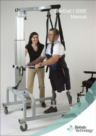
LiteGait I 500E Manual
LiteGait®
2
SERIAL NUMBER
Serial Number of Your Device:
Note: Please keep your serial number in a safe and secure location. The serial number must be provided when seeking service for your LiteGait device. The serial number provides us access to technical information regarding your device.
3
2
WARNING LiteGait
Max Height
Max Weight
500E
8 Feet 9 Inches
500 Lbs
500ES
7 Feet 4 Inches
500 Lbs
400E
9 Feet 2 Inches
400 Lbs
400ES
7 Feet 11 Inches
400 Lbs
360E
7 Feet 8 Inches
360 Lbs
Use only under the direct supervision of a health care professional or caregiver Brakes should remain locked except when moving over ground Operate only on a smooth, level floor
4
3
Dear LiteGait User Congratulations on your recent purchase of LiteGait, the most innovative gait and balance therapy training system available today. Clinical Support As you know, LiteGait may be used with a wide variety of patient impairment levels and conditions. If you have questions about the possible uses of LiteGait with particular patients or are in needs of some ideas for ways to use LiteGait more effectively, please do not hesitate to contact us for information relating to your individual situation. Our website also offers valuable information. Maintenance Like all quality therapy equipment, LiteGait requires regular inspections. Attached at the back of this manual is a Maintenance Checklist for your convenience. Please complete the checklist every 6 months to ensure the efficient, safe and effective operation of the LiteGait unit. If you should find a problem with a LiteGait part, please contact Technical Support immediately. Support Contacts Rehab Technology Pty Ltd distributes LiteGait throughout Australia & New Zealand: Technical Support
Telephone 1300 60 99 50 [email protected]
Clinical Support
Telephone 1300 60 99 50 [email protected]
Customer Support
Telephone 1300 60 99 50 [email protected]
Website
www.LiteGait.com www.rehabtechnology.com.au
User Forum
www.LiteGait.org
Rehab Technology Pty Ltd Telephone 1300 60 99 50 Email [email protected] Website www.rehabtechnology.com.au ABN 42 109 553 264
5
4
TABLE OF CONTENTS UNPACKING AND ASSEMBLY ... 6 ABOUT YOUR UNIT ...9 ASSEMBLY DIAGRAM ... 10 USING YOUR LITEGAIT ... 11 How to adjust the height of the yoke ... 11 Overhead Buckles and Straps ... 12 Harness Application ... 13 Harness and Groin Piece Preparation ... 13 How to put on the Harness ... 13 Harness Application in Supine (Laying on Back) ... 14 Harness Application While Standing ... 15 Groin Piece Attachment ... 15 How to Connect the Harness to your LiteGait ... 17 Control Unit... 18 Adjusting the Handlebars... 19 Base and Casters... 20 Total-Lock Caster ... 20 Base and Casters... 21 Directional-Lock Caster ... 21 BiSym Scale (Optional) ... 22 Over a Treadmill ... 26 Over Ground... 27
MAINTENANCE CHECKLIST ... 33 TROUBLESHOOTING Power System... 35 Casters / Base ... 36 Harness ... 37 Digital BiSym (Optional) ... 38
RESOURCE DIRECTORY ... 39
6
5
UNPACKING AND ASSEMBLY Tools Required: Scissors 1/2 inch socket or open-end wrench 5/16 inch Allen wrench (provided) LiteGait I Assembly Instructions: TWO PEOPLE ARE REQUIRED FOR SAFE ASSEMBLY Read below & follow pictures on the following pages: Note: The LiteGait in the photos may not look like yours, but the steps are the same. 1. Inspect shipment and note any visual damage to box and/or crate 2. Remove screw located at the bottom of crate 3. Lift off exterior box in order to expose equipment 4. Loosen handle bar knobs and raise handle bars 5. Remove cardboard box, (CAUTION: DO NOT USE UTILITY KNIFE TO OPEN BOX) 6. Inspect contents of card board box for damage 7. Carefully cut all black plastic straps. 8. Free and remove base with two people. 9. Set base over pallet as pictured with actuator next to base. 10. Cut packaging from base. 11. Locate and remove hand switch from inside base, set aside next to control box. 12. Remove covers for battery compartment and control box cover; set aside. 13. Locate 4 black steel bolts and Allen wrench in small box. 14. If black bolts are in base, remove with Allen wrench provided. 15. Locate bolts holding actuator to pallet. Undo bolts with ½ inch socket or wrench, loosen actuator from pallet with one person holding the actuator steady while loose. 16. Lower handlebar base on actuator and tighten knobs before lifting. 17. Ensure base is ready for positioning actuator. 18. Two people lift actuator from pallet to base. 19. Orient the actuator on the base (the yoke arms and handlebars point in the same direction as the base legs). Line up the holes for bolts to be inserted. 20. Insert bolts, hand tighten bolts (ensure one person holds actuator steady until secure). 21. The 5/16 inch Allen wrench may be used to tighten bolts (careful not to over tighten). 22. Line up actuator connector, and insert actuator connector. 23. Twist/release the red button; check 4-bar battery indicator on control box. 24. Verify connection and operation by moving actuator up/down by pressing the arrows on the hand switch. 25. If hand switch fails to operate the actuator, check connections to control box. 26. Carefully remove all shrink-wrap from the unit. 27. Verify performance of each locking and directional caster. 28. Feel free to call 1-800-332-9255 Extension 7104 for Mobility Research Support during this assembly.
7
6
1. Inspect box for damage 2. Undo base boards screws
3. Remove box and set aside
Expose & examine content
4. Loosen knobs
5. Remove box
Open box (CAUTION: DO NOT USE UTILITY KNIFE)
6. Inventory box content
7. Cut straps
Cut straps
8. Free and remove base
9. Free and remove base
11. Locate and remove hand switch
Move hand switch to side
12. Remove covers; set aside
10. Cut packaging from base
8
7
13. Ready base for actuator
15. Remove bolts; ½” wrench
16. Lower Handlebar base; secure
18. 2 people raise actuator
19. Set actuator on base
Line up holes; insert bolts
20. Hand tighten
21. ½”wrench; don’t over tighten
22. Line up actuator connector
Insert actuator connector
23. Release Red EMO button
4 battery indicator bars
24. Test raise actuator up/down
Unwrap casters
26. Remove shrink wrap; Do Not use knife! Scissors if necessary, avoid cutting socks
27. Directional-Lock caster
Locking caster
9
Pull up to unlock casters
8
ABOUT YOUR UNIT LiteGait® is comprised of several parts: YOKE: The yoke is a Y-shaped piece that has four female buckles at the ends. It is attached to the actuator with a flat plate secured by four bolts. OVERHEAD STRAPS: The overhead straps consist of four 44” long adjustable straps with male connectors at one end and padded female buckles at the opposite end. The male connectors attach to the yoke buckles and the female buckles attach to the harness. The overhead straps provide postural support for the patient. HARNESS/GROIN PIECE: The harness is an adjustable wrap with a buckle closure in the front and three adjustable straps on each side. There are four male connectors at the top of the harness that attach into the female buckles of the overhead straps. The four female buckles at the bottom of the harness allow for the connection of the groin piece. The H-shaped stitching on the groin piece denotes the top (or body side) of the piece. ACTUATOR: The actuator is the mechanism that raises and lowers the yoke. It consists of a concentric expanding and retracting square tower that houses the DC motors, gearing and the screw mechanism. It also provides the structural base to which the adjustable handlebars are attached. CONTROL UNIT: The control unit is the junction box for the battery power, handheld switch and contains electrical safety protection circuitry. It is located within a compartment of the actuator. The battery pack connects to this unit and is also located within a compartment of the actuator. HANDLEBARS: Your unit has two adjustable handlebars. The handle bars are attached to the unit using two knobs. (Note: Over tightening the knobs may cause damage) BASE: The base consists of two horizontal bars connected by two U-shaped tubes. The base has an open end and a closed end where the actuator and battery pack are placed. The base moves freely over ground or can be locked into place during use over a treadmill. However, your unit must be locked into place at all other times. CASTERS: Four casters are attached to the base. Two locks on one side of the base are locking brakes and the two on the opposite side are directional locks. Be certain to lock both caster brakes when using the unit over a treadmill or when connecting the patient to the unit. NEVER leave the patient unattended in the unit. BISYM (Optional): The BiSym Scale is installed on top of the actuator and provides a display of the pounds/kilograms of support provided by each arm of the yoke. The load cells that are installed in the yoke sense the load on the yoke and feed it to the BiSym Scale for processing and display.
10
9
ASSEMBLY DIAGRAM
Drop-Down Yoke
Buckle Assemblies Actuator Handle Bar Assembly
Battery Compartment
Control Unit
Base Frame
Total Locking Casters
Directional Locking Casters
11
10
USING YOUR LiteGait® How to adjust the height of the yoke The LiteGait powered yoke is raised and lowered by a hand- held switch with two up and two down arrows. Raising the yoke: Verify that LiteGait has clearance above the yoke. Press the up arrows on the hand-held remote switch. Release the button when the yoke is at the desired height. Lowering the yoke: Verify that LiteGait has clearance below the yoke. Press the down arrows on the hand-held remote switch. Release the button when the yoke lowers to the desired height. Maintain at least 5" clearance above the patient's head.
Drop-Down Yoke
12
11
USING YOUR LiteGait® Overhead Buckles and Straps Each of your unit’s four straps can be individually adjusted. Adjust each strap to assure that the patient is in a fully upright position in the correct posture for walking. 1. To tighten straps: With one hand pull up on the strap attached to the harness. With the other hand, pull down on the free end of the strap. 2. To loosen straps: With one hand, hold the overhead buckle outwards. With the other hand pull down on the part of the strap attached to the harness. 3. To prevent the patient leaning to one side, e.g. right side: Tighten the front and back straps on the right side. 4. To prevent the patient from leaning forward: Tighten the right and left FRONT straps. 5. To prevent the patient from leaning backward: Tighten the right and left BACK straps. 3. To prevent the patient leaning to one side, e.g. right side: Tighten the front and back straps on the right side. 4. To prevent the patient from leaning forward: Tighten the right and left FRONT straps. 5. To prevent the patient from leaning backwards: Tighten the right and left BACK straps
13
12
USING YOUR LiteGait® Harness Application Harness and Groin Piece Preparation 1. Pick the appropriate harness and groin piece for the patient (based on patient girth). 2. Estimate the harness girth before placing on the patient by folding the harness in half so that the ends meet. Then, hold the harness in front of the torso to estimate the width from one side of the body to the other. 3. Tighten or loosen the 3 rows of side straps on each side of the harness. (To loosen the side straps lightly pull up on the black tabs on the side buckles.) 4. Keep the harness folded in half and align the top buckles so that they are adjacent with each other. 5. Take the groin piece and adjust the groin strap padding towards the center of the strap before putting it on. 6. Adjust the front groin straps so they are equal in length. 7. Adjust the back groin straps so they are equal in length. 8. Attach the groin piece to the back of the harness. 9. The side of the groin piece with the H-outline stitching (most padded) will go against the patient’s body.
How to put on the Harness The harness was designed to support a patient in an upright position, allowing for full hip extension. This upright posture plays a critical role in the effectiveness of the gait therapy performed with partial weight bearing. The front of the harness wrap refers to the point at which the two ends of the harness meet. The harness can be worn with the closure either in the front or in the back. There are four buckles on the top and bottom of the harness wrap. The four top buckles extend beyond the harness from the top seam and attach to the LiteGait straps. The bottom four buckles attach to the groin piece and do not extend past the bottom seam of the harness.
14
13
USING YOUR LiteGait® Harness Application in Supine (Laying on Back) 1. Patient should be lying down on his/her back. 2. Place one end of the harness on the mid-lower abdomen. 3. Roll the patient on his/her side away from you. 4. Place the harness on the center of his/her back so that the top buckles are equal distances from the spine. 5. Place the lowest harness side strap over the greater trochanter. The greater trochanter is a boney prominence on the side of the upper leg approximately on patient’s hand length below the waist. 6. Pass the groin piece between the legs to the front. 7. Tighten the groin piece at the back leaving enough length for the front to attach. 8. Hold the harness with your hand. 9. Roll the patient back onto his/her back. 10. Wrap the harness to meet the other end in front. 11. Attach the front buckles. 12. Check the midline position of the harness by feeling for both upper buckles behind the patient’s back. (They should be the same distance from the spine.) 13. Rotate the harness to adjust, if necessary. 14. Tighten the lower side straps first, as symmetrically as possible. These straps are crucial to the proper distribution of the patient’s weight and should be as tight as possible. To ensure a snug fit, pull the strap closest to the body towards its black plastic buckle with one hand while pulling the free end with your other hand until you cannot pull anymore. 15. Tighten the middle and upper side straps. Make sure to tighten both sides symmetrically (equally) so that an equal strap length remains on each side. These should be as tight as the patient can tolerate without discomfort. The top strap should not interfere with breathing. Bulges of fatty tissue should be apparent (visible on most patients) as the harness is tightened. These bulges are very important and will allow the harness to securely grab onto the soft tissue of the abdomen, keeping the harness securely in place throughout the training.
15
14
USING YOUR LiteGait® Harness Application While Standing 1. Wrap the harness around the patient’s torso. 2. Place the lowest strap over the greater trochanter. 3. Attach the front buckles. 4. Tighten the lowest straps first (see Tightening side straps section). 5. Attach the groin piece (see Groin piece attachment section).
Groin Piece Attachment 1. Attach the groin piece to the front harness buckles. The stitched side of the groin piece should be facing up against the body. 2. Hold the padded part of one end of the groin piece with one hand. 3. Pull it against the patient’s leg. Keep holding it while the other hand pulls the free end of the groin strap. 4. Tighten the groin strap snugly so there is NO slack. 5. Repeat on the other side. 6. Pull out any wrinkles or bunching from the patient’s clothing. 7. Sit the patient up or stand the patient, if safe
ENSURE AT ALL TIMES THAT THE BOTTOM STRAP OF THE HARNESS IS AT THE LEVEL OF THE GREATER TROCHANTER (HIP JOINT CREASE). Contrary to what may seem reasonable, a loose groin piece DOES NOT impart greater comfort to the patient, but allows the harness to slide up the trunk, putting unwanted load/force on the groin area. Tighten the groin strap so that no slack remains in the straps. This assures that the harness will not ride up on the patient.
16
15
USING YOUR LiteGait® How to Connect the Harness to your LiteGait 1. Lock the caster brakes. 2. Adjust the yoke to the correct position, giving the patient approximately 5-6 inches of head clearance. 3. Extend the overhead straps until they are long enough to reach the upper connection on the harness. Attach the four buckles that hang from the overhead straps to the appropriate buckles on the harness. Pull on the straps until taut. 4. With the patient in the harness, bring the patient into a standing position directly under the yoke buckles. Have the patient hold the handlebars. Adjust the handlebar height to suit the patient. 5. Your unit can now be used for over ground therapy, or to assist the patient in stepping onto the treadmill. 6. With higher level patients, the unit may be positioned over the treadmill before the patient is buckled into place.
NOTE: Under no circumstances should a patient have ALL the weight removed from the legs for more than two minutes at a time.
18
17
USING YOUR LiteGait® Control Unit Control Box is the junction box (connecting point) for LiteGait power system. The actuator cord(s), the handheld switch, the battery, and the power cord all plug into this unit. It is located in the base opposite to the battery side and is equiped with a red STOP button for emergency shut down. Press this button to cut the power to the actuator and stop all movements or lifting action. Twist the red button to power up before using the lift mechanism. On the control box there is a small digial display which notifies you of the remaining battery life. It will indicate a fully charged battery with four bars. Once the battery charge is depleted to below 50% a plug icon appears in the display suggesting it is time to recharge the batteries. Below 25% charge the word STOP appears on the display. In order for the contorl box and LiteGait to work, the charging cord must be unplugged from the wall, the red button must be released and the battery must be charged.
Red Stop Button Battery Monitor
Hand Switch Actuator Cord 1
Charging Cord
Actuator Cord 2 Battery
19
18
USING YOUR LiteGait® Adjusting the Handlebars Raising and lowering the handle bars: Loosen each knob in equal portions. The knobs should only need to be turned once to free the handle bars. Once the knobs are loosened slide the handle bars to the desired height. Hand tighten both knobs equally. Again, the knobs should only need to be tightened one rotation.
20
19
USING YOUR LiteGait® Base and Casters Total-Lock Caster LiteGait is equipped with four or six casters. Half are total-lock casters and half directional lock casters. Each leg has one type of caster and it is clearly marked. Directional lock casters have a green or black brake lever. Standard casters have a gray or silver brake lever. To lock the total-lock casters press the caster brake until you feel the brake snap into place. The caster brakes should be locked whenever the LiteGait is not being moved over the ground.
CAUTION: While locking the casters prevents rolling of the unit, it does not prevent the unit from sliding on a sloped, slippery floor. The unit should only be used on a flat floor and away from stairs and ramps. NEVER leave a patient unattended in the unit.
21
20