Instructions
80 Pages
Preview
Page 1
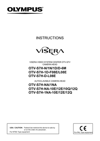
INSTRUCTIONS
VISERA VIDEO SYSTEM CENTER OTV-S7V CAMERA HEAD
OTV-S7H-N/1N/1D/D-6M OTV-S7H-1D-F08E/L08E AUTOCLAVABLE CAMERA HEAD
OTV-S7H-NA/1NA OTV-S7H-NA-10E/12E/10Q/12Q OTV-S7H-1NA-10E/12E/12Q
For NTSC Type equipment
For PAL Type equipment
HHHHHHHHHHHHHHHHHHHHHHHHHHHHHHHHHHHHHHHHHHHH ©2002 Olympus Medical Systems Corp. All rights reserved. No part of this publication may be reproduced or distributed without the express written permission of Olympus Medical Systems Corp. OLYMPUS is a registered trademark of Olympus Corporation.
HHHHHHHHHHHHHHHHHHHHHHHHHHHHHHHHHHHHHHHHHHHH
Manufactured by 2951 Ishikawa-cho, Hachioji-shi, Tokyo 192-8507, Japan Fax: (0426)46-2429 Telephone: (0426)42-2111
Distributed by (Premises/Goods delivery) Wendenstrasse 14-18, D-20097 Hamburg, Germany (Letters) Postfach 10 49 08, D-20034 Hamburg, Germany Telephone: (040)237730
Two Corporate Center Drive, Melville, N.Y. 11747-3157, U.S.A. Fax: (631)844-5442 Telephone: (631)844-5000
KeyMed House, Stock Road, Southend-on-Sea, Essex SS2 5QH, United Kingdom Telex: 995283 Fax: (01702)465677 Telephone: (01702)616333
491B, River Valley Road #12-01/04, Valley Point Office Tower, Singapore 248373 Fax: 6834-2438 Telephone: 6834-0010
Room 1406, E Tower, GongYuan No.6 Royal Palace, No.6 GongYuanXiJie, Jian Guo Men Nei, DongCheng District, Beijing, 100005, China Fax: (10)6518-0865 Telephone: (10)6518-8080
117071, Moscow, Malaya Kaluzhskaya 19, bld. 1, fl.2, Russia Fax: (095)958-2277 Telephone: (095)958-2245
31 Gilby Road, Mount Waverley, VIC., 3149, Australia Fax: (03)9543-1350 Telephone: (03)9265-5400
6100 Blue Lagoon Drive, Suite 390 Miami, FL 33126-2087, U.S.A. Fax: (305)261-4421 Telephone: (305)266-2332
GC7533 08
Printed in Japan 20040729 :0000
Contents
Contents Labels and Symbols...
1
Important Information - Please Read Before Use...
2
Intended use...
2
Instruction manual...
2
User qualifications...
2
Instrument compatibility...
2
Reprocessing and storage...
3
Repair and modification...
3
Signal words...
3
Dangers and warnings...
4
Cardiac applications...
5
Precautions against frozen or lost endoscopic images...
6
Chapter 1
Checking the Package Contents...
7
Chapter 2
Nomenclature and Functions...
8
Chapter 3
Preparation and Inspection...
12
3.1
Scope selection...
13
3.2
Inspection of the camera head...
18
3.3
Preparation of ancillary equipment...
18
3.4
Connecting the camera head to the VISERA video system center OTV-S7V...
18
3.5
Connecting the video coupler to the video adapter...
21
3.6
Connecting the video adapter to the camera head (OTV-S7H-N/1N/1D/NA/1NA/D-6M only)...
21
Connecting the endoscope...
22
Operation...
27
4.1
Focus adjustment...
29
4.2
Positioning the scope image...
31
4.3
Color adjustment...
33
4.4
Setting the remote control switches (except for OTV-S7H-1D-F08E
3.7
Chapter 4
4.5
/L08E)...
34
Finder observation (OTV-S7H-1D-F08E only)...
35
CAMERA HEAD, AUTOCLAVABLE CAMERA HEAD
i
Contents
Chapter 5
Reprocessing: General Policy...
36
5.1
Instructions...
36
5.2
Precautions...
36
Chapter 6
Agents...
38
6.1
Compatibility summary...
38
6.2
Detergent solution...
40
6.3
Disinfectant solution...
40
6.4
Rinsing water...
40
6.5
ETO gas sterilization...
41
6.6
Steam sterilization (autoclaving)...
42
Chapter 7
Cleaning, Disinfection and Sterilization Procedures ...
43
7.1
Required reprocessing equipment...
43
7.2
Cleaning, disinfection and sterilization procedures...
45
7.3
Precleaning...
49
7.4
Manual cleaning...
55
7.5
High-level disinfection...
56
7.6
Sterilization...
58
Care, Storage and Disposal...
60
8.1
Wiping the surface and cover glass...
60
8.2
Storage...
62
8.3
Disposal...
62
Troubleshooting...
63
Returning the camera head for repair...
63
Appendix...
65
System chart...
65
Operating environment...
68
Transportation and storage environment...
68
Specifications...
69
Chapter 8
Chapter 9
ii
Compatible Reprocessing Methods and Chemical
CAMERA HEAD, AUTOCLAVABLE CAMERA HEAD
Labels and Symbols
Labels and Symbols Safety-related labels and symbols are attached to the instrument at the locations shown below. If labels or symbols are missing or illegible, contact Olympus. Refer to instructions. Type CF Applied Part
Warning plate Caution and model name.
Warning plate *Example from OTV-S7H-N S NTSC
S PAL
CAMERA HEAD, AUTOCLAVABLE CAMERA HEAD
1
Important Information -- Please Read Before Use
Important Information - Please Read Before Use Intended use These instruments have been designed to be used with an Olympus VISERA video system center OTV-S7V, video adapter, video coupler, endoscope, light source, video monitor and other ancillary equipment for endoscopic observation, diagnosis and treatment. Do not use these instruments for any purposes other than their intended uses.
Instruction manual This instruction manual contains essential information on using this instrument safely and effectively. Before use, thoroughly review this manual and the manuals of all equipment which will be used during the procedure and use the instruments as instructed. Keep this and all related instruction manuals in a safe, accessible location. If you have any questions or comments about any information in this manual, please contact Olympus.
User qualifications The operator of this instrument must be a physician or medical personnel under the supervision of a physician and must have received sufficient training in clinical endoscopic technique. This manual, therefore, does not explain or discuss clinical endoscopic procedures.
Instrument compatibility Refer to the “System chart” in the Appendix to confirm that this instrument is compatible with the ancillary equipment being used. Using incompatible equipment can result in patient injury and/or equipment damage.
2
CAMERA HEAD, AUTOCLAVABLE CAMERA HEAD
Important Information -- Please Read Before Use
Reprocessing and storage This instrument was not disinfected or sterilized before shipment. Before using this instrument for the first time, reprocess it according to the instructions given in Chapter 5, “Reprocessing: General Policy” through Chapter 7, “Cleaning, Disinfection and Sterilization Procedures”. After using this instrument, reprocess and store it according to the instructions given in Chapters 5 through 8. Improper and/or incomplete reprocessing or storage can present an infection control risk, cause equipment damage or reduce performance.
Repair and modification This instrument does not contain any user-serviceable parts. Do not disassemble, modify or attempt to repair it; patient or user injury and/or equipment damage can result. Problems appear to be malfunctions, contact Olympus.
Signal words The following signal words are used throughout this manual:
Indicates an imminently hazardous situation which, if not avoided, will result in death or serious injury.
Indicates a potentially hazardous situation which, if not avoided, could result in death or serious injury.
Indicates a potentially hazardous situation which, if not avoided, may result in minor or moderate injury. It may also be used to alert against unsafe practices or potential equipment damage.
Indicates additional helpful information.
CAMERA HEAD, AUTOCLAVABLE CAMERA HEAD
3
Important Information -- Please Read Before Use
Dangers and warnings Follow the dangers and warnings given below when handling this instrument. This information is to be supplemented by the dangers, warnings and cautions given in each chapter.
S Failure to adhere to the following precautions may place the patient and medical personnel in danger of electric shock. -- When this equipment is used to examine a patient, do not allow the metal parts of the endoscope or its accessories to touch metal parts of other system components. This instrument is electrically connected to metal parts of other system components, and contact may cause unintended current flow to the patient. -- Do not prepare, inspect or use this equipment with wet hands. S Never install and/or operate the OTV-S7V in the following locations. Otherwise, an explosion or a fire may occur. -- The concentration of oxygen is high. -- Oxidizing agents (such as nitrous oxide [N2O]) are present in the atmosphere. -- Flammable anesthetics are present in the atmosphere.
S Be sure to prepare another camera head to avoid that the examination must be interrupted due to equipment failure or malfunction. S This product may interfere with other medical electronic equipment used in combination with it. Before use, fully confirm the compatibility of this instrument with all equipment to be used with it. S Do not use this product in any place where it may be subject to strong electromagnetic radiation (for example, in the vicinity of a microwave therapeutic device, MRI, wireless set, short-wave therapeutic device, cellular/portable phone, etc.). This may impair the performance of the product.
4
CAMERA HEAD, AUTOCLAVABLE CAMERA HEAD
Important Information -- Please Read Before Use
Cardiac applications S Use only the devices listed in the “System chart” for endoscopic observation or treatment of the heart or areas near the heart. Other combinations of equipment may cause ventricular fibrillation or seriously affect the cardiac function of the patient. S For cardiac applications, never support the endoscope with a metal surgical arm that is not electrically isolated from the ground. If not isolated, the endoscope will be connected to the ground through the surgical arm and bed, and will conduct unexpected leakage current, which may seriously affect the cardiac function of the patient. S The use of medical devices not specifically designed for cardiac applications may cause ventricular fibrillation or seriously affect the cardiac function of the patient. As specified by international standard IEC 60601-1, any “Applied Part” used for observation or treatment of the heart or areas near the heart must meet “TYPE CF APPLIED PART” requirements for low electrical leakage current. When using metal endoscopes for endoscopic cardiac applications, the “Applied Part” requirements include all devices directly connected to the endoscope, such as the light guide cable, camera head, and telescope holder. Each of these devices must individually meet the “TYPE CF APPLIED PART” requirements for leakage current limits if they are to be used for cardiac applications.
S The Olympus light guide cables and camera heads listed in the “System chart (TYPE CF APPLIED PART)” which are suitable for cardiac applications bear a
symbol.
S The Olympus surgical holder for telescope SH-1 has an electrically isolated arm structure that isolates the endoscope from the ground. This design makes the SH-1 suitable for cardiac applications.
CAMERA HEAD, AUTOCLAVABLE CAMERA HEAD
5
Important Information -- Please Read Before Use
Precautions against frozen or lost endoscopic images S If the endoscopic image unexpectedly disappears or a frozen image cannot be restored during an examination, immediately stop using the instrument and withdraw the endoscope from the patient. Continued use of the endoscope under these conditions may cause patient injury, bleeding and/or perforation. S Follow the precautions given below. Otherwise, the endoscopic image may disappear unexpectedly, or it may not be possible to restore a frozen image. -- Never clean, disinfect, sterilize or store this instrument together with sharp-tipped instruments (tweezers, forceps, knives, etc.). These could scratch or tear holes in the camera cable, which could allow water to penetrate and damage electrical circuits inside the instrument. -- Do not drop the camera head or allow it to strike other objects. Strong impacts could damage the electrical circuits inside the instrument. -- Make sure that the video plug and its electrical contacts are completely dry before connecting the plug to the OTV-S7V. Wet contacts could cause the equipment to malfunction. -- Never excessively bend, pull, twist, coil, squeeze or apply a crushing force to the camera cable. The camera cable could become damaged. -- Do not use excessive force when wiping the external surfaces of the camera cable. Otherwise, the camera cable could become damaged. -- While the camera head is attached to the endoscope, never attempt to lift the entire assembly by the camera cable. Doing so could damage the cable. -- Never use a clamp or forceps to attach the camera cable to another object. Doing so could damage the cable.
6
CAMERA HEAD, AUTOCLAVABLE CAMERA HEAD
Chapter 1 Checking the Package Contents
Chapter 1 Checking the Package Contents Match all items in the package with the components shown below. Inspect each item for damage. If the instrument is damaged, a component is missing or you have any questions, do not use the instrument; immediately contact Olympus. This instrument was not disinfected or sterilized before shipment. Before using this instrument for the first time, reprocess it according to the instructions given in Chapter 5, “Reprocessing: General Policy” through Chapter 7, “Cleaning, Disinfection and Sterilization Procedures”. Depending upon the camera head purchased, it may appear different from that shown in the figure below.
Instruction manual
Camera head
CAMERA HEAD, AUTOCLAVABLE CAMERA HEAD
7
Chapter 2 Nomenclature and Functions
Chapter 2 Nomenclature and Functions 1. Adapter mount 2. Remote control switch SW1
2. Remote control switch SW2
OTV-S7H-N/1N
3. Color code 14. UP mark 13. Video plug 12. Camera cable
14. UP mark
15.Protective cap
13. Video plug
Electrical contacts
2. Remote control switch SW2 2. Remote control switch SW1
Only OTV-S7H-D-6M 1. Adapter mount
3. Color code
1. Adapter mount
2. Remote control switch SW2
3. Color code
OTV-S7H-1D/D-6M
8
2. Remote control switch SW1
OTV-S7H-NA/1NA
CAMERA HEAD, AUTOCLAVABLE CAMERA HEAD
Chapter 2 Nomenclature and Functions
4. Endoscope mount
6. Endoscope mount lock
5. Endoscope lock button
8. Finder cap
7. Finder
9. Focus ring
11. Main body
3. Color code
OTV-S7H-1D-F08E/L08E 2. Remote control switch SW1 2. Remote control switch SW3
4. Endoscope mount
2. Remote control switch SW2 9. Focus ring
6. Endoscope mount lock
4. Endoscope mount
9. Focus ring
2. Remote control switch SW3 2. Remote control switch SW1
3. Color code 10. Endoscope lock ring
3. Color code
2. Remote control switch SW2 10. Endoscope lock ring
OTV-S7H-NA-10Q/12Q, OTV-S7H-1NA-12Q
OTV-S7H-NA-10E/12E, OTV-S7H-1NA-10E/12E
CAMERA HEAD, AUTOCLAVABLE CAMERA HEAD
9
Chapter 2 Nomenclature and Functions
1. Adapter mount The video adapter is connected to this mount. 2. Remote control switch SW1, SW2 and SW3 The function of the switch is selected on the OTV-S7V VISERA video system center. For more information on selecting the functions, refer to the instruction manual for the OTV-S7V. 3. Color code When using a rigid endoscope without a fiber imaging bundle, use the OTV-S7H-N/D-6M/NA, OTV-S7H-NA-10E/12E/10Q/12Q (camera heads with a black ring). When using a fiberscope or rigid endoscopes with a fiber imaging bundle, use the OTV-S7H-1N/1D/1NA, OTV-S7H-1D-F08E/L08E, OTV-S7H-1NA-10E/12E/12Q (camera heads with an orange ring). 4. Endoscope mount The endoscope is connected to this mount. 5. Endoscope lock button This button is pressed to connect and disconnect the eyepiece of the endoscope to and from the endoscope mount. 6. Endoscope mount lock This lever is moved to lock and free the endoscope mount. 7. Finder Used when observing an endoscopic image with the naked eye. 8. Finder cap This cap is attached to prevent extraneous light from entering the finder when the finder is not used. 9. Focus ring This ring is rotated for initial focus adjustment of the endoscopic image. 10. Endoscope lock ring Operating this ring locks the endoscope to the mount. 11. Main body The image sensor (CCD), which converts the endoscopic image into electrical signals, is located here. 12. Camera cable Connects the camera head to the OTV-S7V VISERA video system center.
10
CAMERA HEAD, AUTOCLAVABLE CAMERA HEAD
Chapter 2 Nomenclature and Functions
13. Video plug This plug is connected to the video connector socket on the front panel of the OTV-S7V VISERA video system center. 14. UP mark When the video plug is connected to the OTV-S7V, this mark is facing upward. 15. Protective cap This cap is attached to the video plug when the camera head is not used.
CAMERA HEAD, AUTOCLAVABLE CAMERA HEAD
11
Chapter 3 Preparation and Inspection
Chapter 3 Preparation and Inspection S Before each case, prepare and inspect this instrument as instructed below. Inspect other equipment to be used with this instrument as instructed in their respective instruction manuals. Should the slightest irregularity be suspected, do not use the instrument; contact Olympus. Damage or irregularity may compromise patient or user safety and may result in more severe equipment damage. S This instrument was not disinfected or sterilized before shipment. Before using this instrument for the first time, reprocess it according to the instructions given in Chapters 5 through 7. Prepare this instrument, other compatible equipment to be used with this instrument (listed in the “System chart” in the Appendix), paper towels, basins, lint-free cloths and personal protective equipment, such as eye wear, face mask, moisture-resistant clothing and chemical-resistant gloves, for the procedure. Refer to the respective instruction manuals for each piece of equipment.
12
CAMERA HEAD, AUTOCLAVABLE CAMERA HEAD
Chapter 3 Preparation and Inspection
3.1
Scope selection Select an endoscope according to the type of the camera head to be used.
Camera head type
Need video adapter
Endoscope mount type
Compatible endoscopes
(optional)? Yes: f, No: -- (magnification) OTV-S7H-N
f
--
OTV-S7H-NA
f
--
OTV-S7H-D-6M
f
--
OTV-S7H-1N
f
--
OTV-S7H-1D
f
--
OTV-S7H-1NA
f
--
OTV-S7H-1D-F08E
-- (0.8 ×)
Eye-piece type
OTV-S7H-1D-L08E
-- (0.8 ×)
Eye-piece type
OTV-S7H-NA-10E
-- (1.0 ×)
Eye-piece type
OTV-S7H-NA-12E
-- (1.2 ×)
Eye-piece type
Rigid g endoscopes p without
OTV-S7H-NA-10Q
-- (1.0 ×)
Quick-lock type
fiber imaging bundle
OTV-S7H-NA-12Q
-- (1.2 ×)
Quick-lock type
OTV-S7H-1NA-10E
-- (1.0 ×)
Eye-piece type
OTV-S7H-1NA-12E
-- (1.2 ×)
Eye-piece type
OTV-S7H-1NA-12Q
-- (1.2 ×)
Quick-lock type
Ri id endoscopes Rigid d without ith t a fiber imaging bundle
Ri id endoscopes Rigid d and d fiberscopes
Ri id endoscopes Rigid d and d fiberscopes
Table 3.1
S The magnification given above is based on the assumption that the magnification of the image on the monitor is 1.0 × when captured using an OTV-S7H-N camera head with an AR-T10 video adapter. S The OTV-S7H-1D/D-6M is not angled. S Two models with angled camera heads are available: one with a viewfinder (OTV-S7H-1D-F08E) and the other without a viewfinder (OTV-S7H-1D-L08E). S The following models are autoclavable: OTV-S7H-NA/1NA, OTV-S7H-NA-10E/12E/10Q/12Q, OTV-S7H-1NA-10E/12E/12Q.
CAMERA HEAD, AUTOCLAVABLE CAMERA HEAD
13
Chapter 3 Preparation and Inspection
` Selection of the scope imaging system S When using camera heads with a black color code, select a rigid endoscope without a fiber image guide. This will provide images with high resolution appropriate for a rigid scope (see Figure 3.1). S When using camera heads with an orange color code, either a rigid endoscope or fiberscope can be used (see Figure 3.2). Scope images with minimized moiré can be obtained by combining this camera head with a fiberscope (see Figure 3.3). S When using the camera head with rigid endoscopes only, select a camera head with a black color code (see Figure 3.1). S When using the camera head with fiberscopes and rigid endoscopes, select a camera head with a orange color code (see Figure 3.2).
Black color code
Black color code
OTV-S7H-NA-10E/12E
Black color code
OTV-S7H-D-6M Black color code
Black color code
OTV-S7H-NA-10Q/12Q
Figure 3.1
14
OTV-S7H-N
CAMERA HEAD, AUTOCLAVABLE CAMERA HEAD
OTV-S7H-NA
Chapter 3 Preparation and Inspection
Orange color code
Orange color code
OTV-S7H-1NA-10E/12E OTV-S7H-1N Orange color code
Orange color code
OTV-S7H-1NA-12Q OTV-S7H-1NA
Orange color code Orange color code
With finder (OTV-S7H-1D-F08E)
Orange color code
Without finder (OTV-S7H-1D-L08E)
OTV-S7H-1D
Figure 3.2
Figure 3.3
CAMERA HEAD, AUTOCLAVABLE CAMERA HEAD
15