OLYMPUS
OLYMPUS Monitors and Image Transmission
IMH-10 and 20 IMAGE MANAGEMENT HUB Instructions Feb 2012
Instructions
8 Pages
Preview
Page 1
USA: CAUTION:
INSTRUCTIONS
Federal law restricts this device to sale by or on the order of a physician.
IMAGE MANAGEMENT HUB
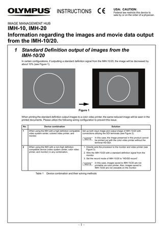
IMH-10, IMH-20 Information regarding the images and movie data output from the IMH-10/20. 1 Standard Definition output of images from the IMH-10/20 In certain configurations, if outputting a standard definition signal from the IMH-10/20, the image will be decreased by about 10% (see Figure 1).
Figure 1 When printing the standard definition output images to a color video printer, the same reduced image will be seen in the printed documents. Please utilize the following wiring configuration to prevent this issue. No.
Device combination
1
When using the IMH with a high definition compatible video system center, colored video printer, and monitor.
Set up both input image and output image of IMH-10/20 with connections utilizing the SDI terminals (see Figure 2).
When using the IMH with a non-high definition compatible device (video system center, color video printer, and monitor) in any combination.
1. Directly wire the processor to the monitor and video printer (see Figure 3).
2
Solution
In this case, the image preserved in this product cannot be printed out with the color video printer without the terminal HD-SDI.
2. Wire the IMH-10/20 with a standard definition signal from the monitor. 3. Set the record mode of IMH-10/20 to “HD/SD record”. In this case, images saved to IMH-10/20 are not printable via color printer. Also, images saved to IMH-10/20 are not viewable on the monitor.
Table 1
Device combination and their solving methods
–1–
2 Regarding the recorded movie data on IMH-10/20 In certain configuration methods the IMH-10/20 changes the aspect ratio of recorded movie data making the video about 10% vertically or horizontally longer. Please utilize the following wiring configuration to prevent this issue. No.
Pattern
Solution
1
When recording high definition movie to Blu-ray disc when in “SD record” mode.
• In the case of high definition video signal and recording to Blu-ray disc, set the record mode to “HD/SD record”. • If recording to Blu-ray disc, record the data by selecting BD (DATA) mode. Data recorded in DATA mode can only be played back with a PC, Not playable with Blu-ray Disc players.
2
When recording standard definition graphic images to Blu-ray disc when in “HD record” mode.
In the case of SDTV image, record on Blu-ray disc in SDTV image quality (setup record mode to “HD/SD recording). Refer to “Instructions 4.3 Recording setting (System settings)” for configuration method.
3 When both CHANNEL 1 and CHANNEL 2 are used for dual channel recording (IMH-20 only) Mixed input of high definition and standard definition into CHANNEL1 and CHANNEL2 of IMH-20 changes the aspect ratio of both movie data and images by about 10% vertically or horizontally. When both CHANNEL1 and CHANNEL2 are used, please use the following solution.
1. Please make both incoming video signals either high definition or standard definition. 2. Please set the recording mode of IMH-20 to “HD/SD record”.
–2–
Wiring method when using a high-definition compatible video system center, color video printer, and monitor.
High definition LCD monitor (OEV261H)
SDI cable (MAJ-1464)
Remote cable (MH-995) Remote cable (MAJ-1021) SDI cable (MAJ-1952)
VTR Remote cable (MAJ-438)
EXERA II video system center (CV-180)
IMAGE MANAGEMENT HUB (IMH-10)
SDI cable (MAJ-1464)
R G
BNC cable (MB-677)
B S Color video printer (OEP-4) RGB cable (MH-984)
Figure 2-1
Connection of EVIS EXERA II video system center (CV-180) and IMAGE MANAGEMENT HUB IMH-10
–3–
High definition LCD monitor (OEV261H)
SDI cable (MAJ-1464)
Remote cable (MH-995) Remote cable (MAJ-1021) SDI cable (MAJ-1952)
VTR Remote cable (MAJ-438)
EXERA II video system center (CV-180)
IMAGE MANAGEMENT HUB (IMH-20) SDI cable (MAJ-1464)
R G
BNC cable (MB-677)
B S Color video printer (OEP-4) RGB cable (MH-984)
Figure 2-2
Connection of EVIS EXERA II video system center (CV-180) and IMAGE MANAGEMENT HUB IMH-20
–4–
Wiring methods when using with any one of non high-definition compatible device (video system center, color video printer, and monitor) in combination. V
SDI cable (MAJ-1464)
S VIDEO
G
B
R
S
High definition LCD monitor (OEV261H) Y/C cable (MH-985)
Color video printer (OEP-4) V MAJ-921, MAJ-970, MAJ-1462, MAJ-1584, or MAJ-1586
S VIDEO S
B G R Remote cable (MH-995)
BNC cable (MB-677)
EVIS LUCERA video system center (CV-260) HDTV/SDTV monitor cable (MAJ-1586)
Remote cable (MAJ-1021)
IMAGE MANAGEMENT HUB (IMH-10)
Figure 3-1
Connection of EVIS LUCERA video system center (CV-260) and IMAGE MANAGEMENT HUB IMH-10
–5–
High definition LCD monitor (OEV261H)
Y/C cable (MH-985)
Y/C cable (MH-985) RGB cable (MH-984)
VISERA video system center (OTV-S7V)
VTR remote cable (MAJ-438)
IMAGE MANAGEMENT HUB (IMH-10) OEP cable (MH-987) SDI cable (MAJ-1464)
R
BNC cable (MB-677)
G B S Color video printer (OEP-4)
Figure 3-2
Connection of VISERA video system center (OTV-S7V) and IMAGE MANAGEMENT HUB IMH-10
–6–
High definition LCD monitor (OEV261H)
Y/C cable (MH-985)
Y/C cable (MH-985) RGB cable (MH-984)
VISERA video system center (OTV-S7V)
VTR remote cable (MAJ-438)
IMAGE MANAGEMENT HUB (IMH-20) OEP cable (MH-987) SDI cable (MAJ-1464)
R
BNC cable (MB-677)
G B S Color video printer (OEP-4)
Figure 3-3
Connection of VISERA video system center (OTV-S7V) and IMAGE MANAGEMENT HUB IMH-20
–7–
4 Symbols The meaning(s) of the symbol(s) shown on this instructions are as follows: Manufacturer
Authorized representative in the European Community
Low voltage directive and EMC directive
Manufactured by 2951 Ishikawa-cho, Hachioji-shi, Tokyo 192-8507, Japan Fax: (042)646-2429 Telephone: (042)642-2111
This device complies with the requirements of Directive 2006/95/EC concerning electrical equipment designed for use within certain voltage limits. This device complies with the requirements of Directive 2004/108/EC concerning electromagnetic compatibility when used in combination with devices bearing CE marking either on the product or in its instructions. This device meets EN EN61000-6-4.
Distributed by (Premises/Goods delivery) Wendenstrasse 14-18, 20097 Hamburg, Germany (Letters) Postfach 10 49 08, 20034 Hamburg, Germany Fax: (040)23773-4656 Telephone: (040)23773-0
KeyMed House, Stock Road, Southend-on-Sea, Essex SS2 5QH, United Kingdom Fax: (01702)465677 Telephone: (01702)616333
3500 Corporate Parkway, P.O. Box 610, Center Valley, PA 18034-0610, U.S.A. Fax: (484)896-7128 Telephone: (484)896-5000
5301 Blue Lagoon Drive, Suite 290 Miami, FL 33126-2097, U.S.A. Fax: (305)261-4421 Telephone: (305)266-2332
117071, Moscow, Malaya Kaluzhskaya 19, bld. 1, fl.2, Russia Fax: (095)958-2277 Telephone: (095)958-2245
Olympus-Tower, 114-9 Samseong-Dong, Gangnam-Gu, Seoul 135-090 Korea Fax: (02)6255-3494 Telephone: (02)6255-3210
A8F, Ping An International Financial Center, No. 1-3, Xinyuan South Road, Chaoyang District, Beijing, 100027 P.R.C. Fax: (86)10-5976-1299 Telephone: (86)10-5819-9000
491B, River Valley Road #12-01/04, Valley Point Office Tower, Singapore 248373 Fax: 6834-2438 Telephone: 6834-0010
31 Gilby Road, Mount Waverley, VIC., 3149, Australia Fax: (03)9543-1350 Telephone: (03)9265-5400
GT8832 01
–8–
©2012 OLYMPUS MEDICAL SYSTEMS CORP. All rights reserved. Printed in Japan 20120214 *0000