Installation Guide
17 Pages
Preview
Page 1
VMC-1 Installation Guide
1 of 17
VMC-1 Installation Guide
Features & Benefits Main benefits and features for the system in general:
Main benefits and features for the DICOM configuration: DICOM interface for full integration in PACS environment Main benefits and features for the Imaging configuration: High Definition video and image documentation with reporting function Basic material checklist and consumption documentation
2 of 17
VMC-1 Installation Guide
Specifications
3 of 17
VMC-1 Installation Guide
The unit is designed for operation under the following temperature conditions
Dimensions
4 of 17
VMC-1 Installation Guide
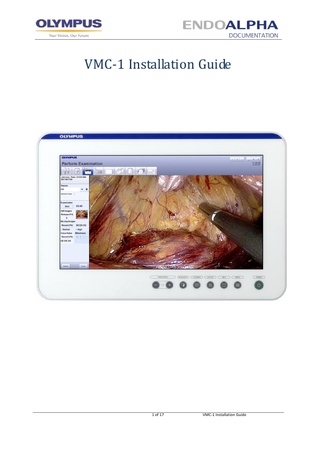
Front view
5 of 17
VMC-1 Installation Guide
Authentication Details Name WINDOWS User Administrator endobase ENDOBASE User Administrator Endobase 1
Password
Role
EB_0lympus endobase
1
Administrator Normal user for daily usage
Administrator endobase
Administrator Doctor (examiner/surgeon)
Note: In the passwords EB_0lympus and EB_0ly the 0 is the number zero and not the letter O.
Hardware Installation Mounting The touch screen panel can be mounted on any device which supports VESA 100 or VESA 200 and can carry a weight of at least 13kg. The system will be delivered with four screws for mounting. For mounting you need to use a monitor arm on a trolley. Main Power Switch You find the main power switch at the bottom of the PC at the right side: Note: The power switch needs to only be used when the system is started the first time after all connections have been made successfully.
6 of 17
VMC-1 Installation Guide
Connector Panel
Note :
COM 1 and COM 2 are galvanic separated. Please connect USB extended cable to both USB 2.0 ports and 1 USB 3.0 port
7 of 17
VMC-1 Installation Guide
Installing VMC-1 on a GI Tower 1. The VMC-1 is intended to be mounted on a monitor arm, or adequate stand, with VESA mounting plate. Please install VMC-1 on the tower’s monitor arm.
8 of 17
VMC-1 Installation Guide
2. Please install keyboard tray on the trolley. Once installed you can then attach
the keyboard, and use double sided tape to stabilize the keyboard so that it doesn’t move.
9 of 17
VMC-1 Installation Guide
CV-190 connection In order to supply the VMC-1 with an endoscopic image an Olympus CV-190 EVIS EXERA III can be connected. Despite the HD-SDI image the CV-190 provides the possibility to establish a CV communication with ENDOBASE. Required hardware for CV connection: MAJ-1918 – CV Interface Converter Cable 1,8m MAJ-1916 – CV Interface Converter MAJ-1021 – Remote Cable (this will connect to the 2M serial M/F cable) MAJ-1951 – HD SDI cable
10 of 17
VMC-1 Installation Guide
1. Power Connections and Electrical Safety
Work carefully when operating the VMC-1. Make sure that all external cables and connectors are connected correctly to the VMC-1. DANGER
Do not operate the VMC in any of the following cases the power cable or plug is damaged the hardware was exposed to water the hardware was dropped or otherwise damaged
11 of 17
VMC-1 Installation Guide
Please connect the other end to the CyberPower UPS device and in the power port labeled “Surge/Battery” (as seen on the image below).
2. Data / Remote Trigger Cable ENDOBASE DICOM connects to an image source for data and remote control via serial cables (COM port). With remote control the following is possible: Capturing of still images Start/stop of video recording Start/stop of live image during procedure See above CV-190 connection description.
12 of 17
VMC-1 Installation Guide
3. Printer One of the following printers is supplied with every VMC-1 system
The printer power is plugged into the power port labeled “Surge/Battery” (shown below):
Connect the Power Plug to the Belkin UPS
Connect the printer USB cable to the USB extension (2) cable supplied
13 of 17
VMC-1 Installation Guide
Connect the USB/Power cable to the printer and the other end to the DICOM unit in one of the USB ports.
14 of 17
VMC-1 Installation Guide
4. CyberPower UPS The CyberPower UPS will be supplied with every VMC-1 unit sold.
The power plug will be converted to an IEC connection using the IEC convertor cable supplied, which then needs to be plugged in to the trolley’s transformer, located at the bottom of the trolley.
15 of 17
VMC-1 Installation Guide
5. Finally below is an image of how the trolley should look when everything is connected.
16 of 17
VMC-1 Installation Guide
VMC-1 Parts List Item Endobase VMC-1
Item code WD11013A
Tick box
- Power cable Trigger Cable
MAJ-1021
Alternate Trigger Cable Monitor Arm
K10001017
Keyboard Arm
K10001112
Keyboard Printer CyberPower - UPS USB Extension Cable x 3
WC7702
1m Cable Tube
17 of 17
VMC-1 Installation Guide
Returned