Technical Manual
62 Pages
Preview
Page 1
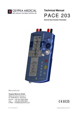
Technical Manual
PACE 203 External Dual Chamber Pacemaker
Manufacturer Osypka Medical GmbH Albert-Einstein-Strasse 3 D-12489 Berlin, Germany Phone: +49 (30) 6392 8300 Fax: +49 (30) 6392 8301 E-Mail: [email protected]
5I-17-013X-B-18
Osypka Medical 2013©
Osypka Medical PACE 203 – Technical Manual
Table of Contents 1 Technical Description 1.1 Overview 1.2 Classifications 1.3 Applicable Standards 1.4 Electronic Block Diagram 1.5 Mechanics
6 6 6 6 7 8
2
9
Function Check
3 Safety Check 3.1 Micro/Macro Shock Protection Tests 3.1.1 Measurement of Enclosure Leakage Current 3.1.2 Measurement of Patient Leakage Current 3.1.3 Insulation Test 3.2 Measurement of Patient Auxiliary Current 3.3 Runaway Protection Test
10 11 12 12 14 14 15
4 Special Service Modes 4.1 Service Mode 4.1.1 Activation of Service Mode 4.1.2 Deactivation of Service Mode 4.1.3 Service Menu
16 16 16 16 16
5 Feature and Compatibility Menu 5.1 Activation of the Feature and Compatibility Menu 5.2 Deactivation of the Feature and Compatibility Menu 5.3 Hardware & Software Compatibility Issues 5.3.1 Firmware 1.29 or higher 5.3.2 Firmware 1.25 + 1.26 + 1.27 + 1.28 5.3.3 Firmware 1.24 5.3.4 Firmware 1.23 5.3.5 Firmware 1.22 5.3.6 Firmware 1.21.1 5.3.7 Firmware 1.21 + 1.20 5.4 LCD Board Generations
17 17 17 17 18 19 19 20 20 21 21 22
6 Pulse Generator Timing 6.1 General 6.1.1 Terms 6.1.2 Symbols 6.2 Mode Characteristics 6.3 Asynchronous modes (V00 or A00) 6.4 Inhibited Single-chamber Modes (VVI or AAI) 6.5 Asynchronous Dual-chamber Mode (D00) 6.6 Dual-chamber Mode without Atrial Stimulation (VDD) 6.7 Dual-Chamber Universal Mode (DDD) 6.8 The Implicitly Adjustable DAI Mode 6.9 The Implicitly Adjustable DVI Mode 6.10 Atrial Trigger Modes (AAT, DDD+AT)
23 23 23 24 24 25 25 26 26 27 28 28 29
7
30
EMC Guidance and Manufacturer’s Declaration
5I-17-013X-B-18
Page 2 of 62
Osypka Medical PACE 203 – Technical Manual
7.1 7.2 7.3 7.4
Electromagnetic Emission/Radiation Electromagnetic Immunity Electromagnetic Immunity for External Cardiac Pacemakers Recommended Safety Distances to Portable and Mobile RF Equipment
8 Appendices 8.1 Error Codes 8.2 Stimulation Amplitude According to ISO Definition 8.3 Waveform of Stimulation Pulse 8.4 Sensitivity for sin² Test Impulses 8.5 Spare Part List 8.6 Circuit Diagrams and Assembly Drawings TM 8.7 Function and Safety Check with SigmaPace 1000 8.7.1 Visual Inspection 8.7.2 Test Equipment & Test Set Up 8.7.3 Supply Current & Power Management 8.7.4 Patient Auxiliary Current 8.7.5 Runaway Protection 8.7.6 Pulse Amplitude 8.7.7 Pulse Duration 8.7.8 Rate 8.7.9 Sensitivity 8.7.10 Noise Detection 8.7.11 A-V Delay 8.7.12 Refractory Period 8.7.13 Electrode Supervisory 8.7.14 Cross Current 8.7.15 CTRL OUT Signal (optional) 8.7.16 Test Protocol
5I-17-013X-B-18
30 31 32 33 34 34 37 38 39 40 42 52 52 53 53 55 55 56 56 56 57 57 58 58 59 59 59 60
Page 3 of 62
Osypka Medical PACE 203 – Technical Manual
Table of Tables Table 1: Medical Device Classifications ...6 Table 2: Applicable Standards ...6 Table 3 Leakage currents ... 11 Table 4 Insulation to be tested ... 12 Table 5 Runaway protection values ... 15 Table 6 Hardware Compatibility Matrix for Firmware 1.29 or higher. ... 18 Table 7 Hardware Compatibility Matrix for Firmware 1.25, 1.26, 1.27 and 1.28. ... 19 Table 8 Hardware Compatibility Matrix for Firmware 1.24. ... 19 Table 9 Hardware Compatibility Matrix for Firmware 1.23. ... 20 Table 10 Hardware Compatibility Matrix for Firmware 1.22. ... 20 Table 11 Hardware Compatibility Matrix for Firmware 1.21.1. ... 21 Table 12 Hardware Compatibility Matrix for Firmware 1.21 and 1.20. ... 21 Table 13 Mode characteristics ... 24 Table 14: Guidance and manufacturer’s declaration – electromagnetic emission ... 30 Table 15: Guidance and manufacturer’s declaration – electromagnetic immunity I... 31 Table 16 Guidance and manufacturer's declaration – electromagnetic immunity II ... 32 Table 17 Safety distances between portable and mobile RF communication equipment... 33 Table 18 PACE 203 Exception Error numbers ... 35 Table 19 PACE 203 Other Error numbers ... 36 Table 20 Peak amplitude vs. ISO 5841-1 amplitudes ... 37 Table 21: List of Spare Parts ... 41
5I-17-013X-B-18
Page 4 of 62
Osypka Medical PACE 203 – Technical Manual
Table of Figures Figure 1: Block Diagram PACE 203 ...7 Figure 2: LCD electronics board with SED1540 controller ... 22 Figure 3: LCD electronics board with ST7522 controller and SED1565 controller (5V) ... 22 Figure 4: LCD electronics board with ST7522 controller and SED1565 controller (3.3V) ... 22 Figure 5 V00 Timing Cycle ... 25 Figure 6 A00 Timing Cycle ... 25 Figure 7 VVI Timing Cycle with Inhibition by V-Sense ... 25 Figure 8 AAI Timing Cycle with Inhibition by A-Sense ... 25 Figure 9 D00 Timing Cycle ... 26 Figure 10 VDD Timing Cycle with V-Sense in AVD ... 26 Figure 11 DDD Timing Cycle with V-Sense in AVD ... 27 Figure 12 DDD Timing Cycle with A-Sense in AEI ... 27 Figure 13 DAI Timing Cycle with A-Sense in AEI ... 28 Figure 14 DVI Timing Cycle with Inhibition by V-Sense in AEI ... 28 Figure 15 DDD Timing Cycle with A-Pace Triggered by A-Sense in AEI ... 29 Figure 16: Text messages for error numbers ... 34 Figure 17 Atrial output pulse (at manufacturer's default settings) ... 38 Figure 18 Ventricular output pulse (at manufacturer's default settings) ... 38 Figure 19: Circuit Diagram of Power Management & Encoder ... 42 Figure 20: Circuit Diagram of MCU & Peripherals ... 43 Figure 21 Circuit Diagram of Stimulation Amplifier ... 44 Figure 22 Circuit Diagram of ECG Amplifier ... 45 Figure 23 Assembly Plan of Power Board top ... 46 Figure 24 Assembly Plan of Power Board bottom ... 47 Figure 25 Assembly Plan of Main Board top ... 48 Figure 26 Assembly Plan of Main Board bottom ... 49 Figure 27 Assembly Plan of Upper Case ... 50 Figure 28 Assembly Plan of Lower Case ... 51
5I-17-013X-B-18
Page 5 of 62
Osypka Medical PACE 203 – Technical Manual
1 Technical Description 1.1 Overview The Osypka Medical PACE 203 is a dual-chamber chamber external pacemaker (also referred to as a pulse generator). This technical manual refers to the PACE 203 either as PACE 203 or PACE 203H. The distinction between PACE 203 and PACE 203H is just a branding issue, not a technical difference. PACE 203 is classified as CF electrical medical equipment1 with an internal power source.
1.2 Classifications Region
Class
Reference
Europe
IIb Medical Product
Council Directive 93/42/EEC of 14 June 1993 (‘Medical Device Directive’), Annex IX
USA
Class III Device
21 CFR 862-892 [807.87(c)]
Japan
Specially Controlled Medical Device
The Pharmaceutical Affairs Law (Law No. 145 dated August 10, 1960) Article 2, Paragraph 5
Class III Medical Devices
PFSB (Yakushoku) Notification No. 0720022, July 20, 2004 and PFSB (Yakushoku) Notification No. 0510 (8), May 10, 2013
Table 1: Medical Device Classifications
1.3 Applicable Standards IEC 60601-1:2012
Medical electrical equipment – Part 1: General requirements for basic safety and essential performance, Edition 3.1
IEC 60601-1-2:2007
Medical electrical equipment – Part 1: General requirements for basic safety and essential performance – Collateral Standard: Electromagnetic compatibility – Requirements and tests, 2nd Edition
IEC 60601-1-6:2010
Medical electrical equipment - Part 1-6: General requirements for basic safety and essential performance – Collateral standard: Usability
IEC 60601-2-31:2011
Medical electrical equipment – Part 2-31: Particular requirements for the basic safety and essential performance of external cardiac pacemakers with internal power source, Edition 2.1
ISO 14971:2012
Medical devices - Application of risk management to medical devices Table 2: Applicable Standards
1 ISO 60601-1
5I-17-013X-B-18
Page 6 of 62
Osypka Medical PACE 203 – Technical Manual
1.4 Electronic Block Diagram Figure 1 shows a block diagram of the electronic circuitry. The Microcontroller & Peripherals represents the digital part of the electronic. Peripherals are addressed by the microcontroller. They exchange data and control signals with the other parts. A ‘watchdog’ circuit performs proper system reset after power up and supervises the software for proper functioning. The ECG Amplifier consists of an atrial and ventricular channel. It is responsible for filtered amplification of P and R waves and generating a trigger signal to the microcontroller if the adjusted sensing threshold is reached. A blanking circuit prevents amplifier overload during pacing. The Stimulation Amplifier generates the stimulation pulses with adjustable amplitudes for both channels: atrial and ventricular. It also contains runaway protection, short circuit detection and stimulation current measurement. The runaway protection limits the rate in case of a component or system failure. The short circuit detection generates a signal to the microcontroller to warn the user in case of a short circuit in the lead system. The stimulation current is measured for determining the impedance of the patient circuit. In case of disconnected patient leads the user is alerted. The Power Management provides all voltages needed for proper functioning of the electronic circuitry. A wrong polarity protection ensures that no hazardous situation may occur if a new battery is inserted in a wrong polarity direction. To maintain pacing during battery change special capacitors supply the pulse generator with energy. The User Interface represents the LCD and all keys and dials. Four LED indicate sensing and pacing in both channels. A beeper supports the optical indication acoustically.
User Interface
ECG Amplifier
Microcontroler & Peripherals
Stimulation Amplifier
Power Management
Figure 1: Block Diagram PACE 203
5I-17-013X-B-18
Page 7 of 62
Osypka Medical PACE 203 – Technical Manual
1.5 Mechanics The pacemaker body is divided unto an upper case, a lower case, a battery cover and a lock. The electronic assembly comprising of two printed circuit boards and the LCD module is embedded in the body. . Upper and lower body cases are made of ABS plastic. Two rubber gaskets ensure protection against liquid ingress. A first gasket separates the upper and the lower part. A second gasket is applied between the battery cover and the lower case. The user interface incorporates 1) Six dial knobs sitting on encoder shafts: a.
High knobs are employed for adjustment of Stimulation rate (‘RATE’), and atrial and ventricular output amplitudes (‘A-STIM’, ‘V-STIM’);
b.
Flat knobs are used for adjustment of AV-delay (‘A-V DLY’) and atrial and ventricular sensitivity thresholds (‘A-SENSE’, ‘V-SENSE’);
2) 9 keys integrated into the key foil; foil material: Polyethylene (PE); 3) LCD display. Open the battery compartment by first moving the battery release button cover located on the back of the device to the side and then push the release button. The battery release button cover is intended to avoid accidental opening of the battery compartment and release of the battery. Inside the battery compartment two springs connect battery terminals and electronic circuitry. A screw spring attached to the release button pulls the button back to its default position. On the top of the PACE 203 there are four protected lead connection terminals (V-, V+, A-, A+) located. They are suitable for plugs with a diameter of 0.9 mm to 2.0 mm. The terminals are made of PA-plastic. On the rear side of the enclosure there is a metal hanger. The metal hanger attached to the rear side of the PACE 203 can be deployed in three snap-in positions to either hang the device or have it stand or lay on a table top.. The CTRL-Out-socket located at the bottom of the PACE 203 is covered by a rubber cap.
5I-17-013X-B-18
Page 8 of 62
Osypka Medical PACE 203 – Technical Manual
2 Function Check The function check shall be made with pacemaker test equipment. There are different models available on market. The chosen model's instructions for use must be followed. As an example for a function check procedure with a pacemaker analyzer see Section 1.1. The following measurements and inspections must be carried out: •
Measuring the stimulation parameters (amplitude, pulse width) in the atrial and ventricular channels
•
Measuring the rate
•
Measuring the sensitivity in the atrial and ventricular channels
•
Inspecting the battery surveillance and measuring the power maintenance time
•
Inspecting the lead surveillance
Additionally the following measurements and inspections may be made: •
Measuring the refractory period in the atrial and ventricular channels
•
Measuring the A-V delay
•
Inspecting the atrial overdrive stimulation
•
Inspecting the emergency setting
•
Inspecting the interference behavior
5I-17-013X-B-18
Page 9 of 62
Osypka Medical PACE 203 – Technical Manual
3 Safety Check This safety check is based on the international standards referred to in the section 1.3 on page 6.
The following measurement equipment and auxiliary means are required: •
Safety tester according to IEC 60601-1
•
Digital multimeter
•
Oscilloscope
•
High voltage tester
•
Metal foil, to get an intimate contact with the insulating enclosure of the PACE 203
•
A metal surface of 20 cm × 25 cm
•
Diverse leads with 2 mm and 4 mm plugs, measuring probes, two 100 kΩ resistors
From a safety point of view, an external pulse generator belongs to the internally powered equipment class and has a CF degree of protection against electric shock. The external pulse generator PACE 203 is characterized as follows: an enclosure made of insulating material; two applied parts (atrial and ventricular channel), each applied part with the two patient connections DIFF (black terminal) and INDIFF (red terminal). The following chapters describe all safety tests contained in the above-mentioned standards, which are applicable to external pulse generators with internal power supply. As a safety check of the PACE 203 at least measuring the patient auxiliary currents must be carried out. As an example for a safety check procedure with a pacemaker analyzer see section 8.7 on page 52.
5I-17-013X-B-18
Page 10 of 62
Osypka Medical PACE 203 – Technical Manual
3.1 Micro/Macro Shock Protection Tests The purpose of this test is to verify the micro/macro shock protection according to the above standards which includes measurement of: •
Enclosure leakage current (source IEC 60601-1, subcl. 19)
•
Patient leakage current between patient connections and enclosure (source IEC 60601-1, subcl. 19)
•
Dielectric strength (source IEC 60601-1 subcl. 14.6 c and IEC 60601-2-31 subcl. 5.2, IEC 60601-1 subcl. 20)
The measuring methods of this test shall strongly agree with the respective IEC standards. The test is divided into three parts: •
Measurement of Enclosure Leakage Current,
•
Measurement of Patient Leakage Current,
•
Insulation Test.
Table 3 shows the allowable values for the leakage currents.
Current
Unit #1
Allowable Value #2
#3
Enclosure leakage current
mA
0.1
Patient leakage current between atrial diff connection and enclosure
mA
0.01
Patient leakage current between atrial indiff connection and enclosure
mA
0.01
Patient leakage current between ventricular diff connection and enclosure
mA
0.01
Patient leakage current between ventricular indiff connection and enclosure
mA
0.01
Patient leakage current with voltage 250 VAC applied between atrial diff connection and enclosure
mA
0.05
Patient leakage current with voltage 250 VAC applied between atrial indiff connection and enclosure
mA
0.05
Patient leakage current with voltage 250 VAC applied between ventricular diff connection and enclosure
mA
0.05
Patient leakage current with voltage 250 VAC applied between ventricular indiff connection and enclosure
mA
0.05
Table 3 Leakage currents
5I-17-013X-B-18
Page 11 of 62
Osypka Medical PACE 203 – Technical Manual
Table 4 shows the insulation to be tested.
Insulation to be tested Case B-d (Basic Insulation) Between enclosure and atrial diff patient connection Between enclosure and atrial indiff patient connection Between enclosure and ventricular diff patient connection Between enclosure and ventricular indiff patient connection Between signal output connections and atrial diff patient connection Between signal output connections and atrial indiff patient connection Between signal output connections and ventricular diff patient connection Between signal output connections and ventricular indiff patient connection Table 4 Insulation to be tested
3.1.1 Measurement of Enclosure Leakage Current The enclosure leakage current shall be measured between different parts of the enclosure according to IEC 60601-1, subcl. 19.1 c and 19.4 g 3. A proper measuring device is also given in accordance with the IEC 60601-1 standard and is shown there in figure 18. The subcl. 2.1.6 of IEC 60601-1 defines as an enclosure also all accessible metal parts, knobs and the like, so for measurement of enclosure leakage current both the socket (CTRL OUT) for connection of a serial interface cable and the pacers hanger shall be taken into account. The exterior surface of the pacer made of insulating material shall be covered with a metal foil (according to IEC 60601-1, subcl. 19.4 g 5) of max. 10 x 20 cm. The metal foil shall be pressed towards the insulating material of the enclosure (using foam/rubber of the same dimension as the metal foil). Taking the above considerations into account the enclosure leakage current shall be measured between: 1. the socket (CTRL OUT) for connection of a serial interface cable and the metal foil pressed against the insulating part of enclosure 2. the pacers hanger and the metal foil pressed against the insulating part of enclosure The measured values shall not exceed the values given in Table 3.
3.1.2 Measurement of Patient Leakage Current The test shall be carried out with the safety tester. Its instructions for use shall be exactly followed. Normal Condition For the normal condition the standard ICE 60601-1, subcl. 19.4 h 6 shall be taken into account where figure 23 shows the proper measuring device. The exterior surface of the pacer made of insulating material shall be covered with a metal foil (according to IEC 60601-1, subcl. 19.4 g 5) of max. 10 x 20 cm. The metal foil shall be pressed towards the insulating material of the enclosure (using foam/rubber of the same dimension as the metal foil). According to the standard IEC 60601-1, subcl. 19.1 e /Appendix K the patient leakage current shall be measured between each patient connection and the enclosure covered with the metal foil. The pacer shall be set to DDD mode with standard parameters. In particular the patient leakage current shall be measured between the parts and the values shall not exceed the values given in Table 3. 5I-17-013X-B-18
Page 12 of 62
Osypka Medical PACE 203 – Technical Manual
Single Fault ConditionAccording to the standard IEC 60601-1, subcl. 19.1 e /Appendix K and the ICE 60601-1, subcl. 19.4 h 7 (measuring device see figure 24) the patient leakage current shall be measured between each patient connection and the enclosure covered with the metal foil for single fault condition applying 250 V (in accordance with IEC 60601-1, subcl. 19.1 b) to each patient connection. The enclosure made of insulating material shall be placed in any position of normal use upon a flat metal surface connected to earth with dimensions at least equal to the plan-projection of the enclosure (see ICE 60601-1, subcl. 19.4 h 7). The pacer shall be set to DDD mode with standard parameters. All other constraints described in case of normal condition for measuring the patient leakage current are also valid for single fault condition. In particular the patient leakage current shall be measured for single fault condition in following cases: 1. with voltage 250 VAC between atrial diff connection and enclosure 2. with voltage 250 VAC between atrial indiff connection and enclosure 3. with voltage 250 VAC between ventricular diff connection and enclosure 4. with voltage 250 VAC between ventricular indiff connection and enclosure The measured values shall not exceed the values given in Table 3.
5I-17-013X-B-18
Page 13 of 62
Osypka Medical PACE 203 – Technical Manual
3.1.3 Insulation Test The test shall be carried out with the high voltage tester. Its instructions for use shall be exactly followed. The insulation test shall occur according to IEC 60601-1, subcl. 20.2 B-d. Values of test voltages are specified in IEC 60601-1, subcl. 20.3, table V. In case of the pacer P203H a basic insulation shall be tested. The exterior surface of the pacer made of insulating material shall be covered with a metal foil (according to IEC 60601-1, subcl. 19.4 g 5) of max. 10 x 20 cm. The metal foil shall be pressed towards the insulating material of the enclosure (using foam/rubber of the same dimension as the metal foil). Care shall be taken that the metal foil is positioned in a manner that flashover does not occur at the edges of insulation linings. If possible, the metal foil should be moved so as to test all parts of the surface. During the insulation test the pacer shall be switched off. The insulation test shall be done for a reference voltage of 50 V ≤ U ref ≤ 150 V (this case is valid for activated EL-backlight). The test voltage shall be equal to 1000 V. The test shall be carried out in accordance with IEC 60601-1, subcl. 20.4. Initially, not more than 500 V shall be applied, then the test voltage shall be gradually raised over a period of 10 s to 1000 V, which shall be maintained for 1 min. after which it shall be gradually lowered over a period of 10 s to less than 500 V. The insulation test shall occur between the parts shown in Table 4.
3.2 Measurement of Patient Auxiliary Current The purpose of this test is to verify the tissue protection, which includes measurement of: •
atrial and ventricular patient auxiliary currents (source IEC 60601-2-31, subcl. 19.3 a)
The Patient Auxiliary Current shall be measured according to the standard IEC 60601-2-31, subcl. 19.3 a. The test conditions are described in the standard IEC 60601-2-31, subcl. 19.4 j 4. For measurement of patient auxiliary current the equipment shall be connected as shown in figure 27 of the general standard to a d.c. measuring device with an input resistance of 100 kΩ. The equipment shall be connected to the measuring device for a minimum of 5 min. before making the patient auxiliary measurement. The patient auxiliary current will be measured just before the pacing pulse. In this case the measured voltage shall not exceed 100 mV. According to the IEC 60601-1, subcl. 19.1 f and g /Appendix K, the measurement of patient auxiliary current shall be done between: 1. atrial diff connection and atrial indiff connection (DDD mode) 2. ventricular diff connection and ventricular indiff connection (DDD mode) 3. atrial diff connection and ventricular indiff connection (DDD mode) 4. ventricular diff connection and atrial indiff connection (DDD mode) 5. atrial diff and atrial indiff, ventricular diff and ventricular indiff connected together (AAI mode) 6. atrial indiff and atrial diff, ventricular diff and ventricular indiff connected together (AAI mode) 7. ventricular diff and ventricular indiff, atrial diff and atrial indiff connected together (VVI mode) 8. ventricular indiff and ventricular diff, atrial diff and atrial indiff connected together (VVI mode)
5I-17-013X-B-18
Page 14 of 62
Osypka Medical PACE 203 – Technical Manual
3.3 Runaway Protection Test The purpose of this test is to verify that the runaway protection limits the pulse rate in the event of a single fault condition (source IEC 60601-2-31, subcl. 51.104 a). To carry out this test, first the service mode of the PACE 203 must be entered. See section 4.1.1 on page 16 for how to activate the service mode. Note that 10 minutes after the last user operation the device automatically terminates the service mode and returns to normal operation. While being in the service mode the check for abnormal settings is disabled and it is possible to dial an abnormal high pacing rate in order to perform the runaway protection test. For the runaway protection test the rate of the stimulation pulse must be measured by an oscilloscope or other suitable equipment. Then with the corresponding dial the pulse rate shall be increased over 220 ppm until the measured rate goes back to the half value (2:1 block). If this happens, the runaway protection correctly works at the rate just adjusted. The test has to be done in AAI and VVI mode and the observed rate values must be as shown in Table 5.
Channel
Unit
Value
Tolerance
#1
#2
#3
#4
Atrial channel runaway protection
ppm
238
±3
Ventricular channel runaway protection
ppm
238
±3
Table 5 Runaway protection values
5I-17-013X-B-18
Page 15 of 62
Osypka Medical PACE 203 – Technical Manual
4 Special Service Modes 4.1 Service Mode The device supports a special Service Mode to be used only by authorized service personal or the manufacturer. The service mode must not be used during a clinical application or while a patient is connected to the device. While in service mode the device behaves different compared with normal mode in some ways: •
Allows access to the Service Menu.
•
During service mode the lock symbol is blinking.
•
The check for abnormal settings is disabled in service mode.
•
In service mode it is possible to dial an abnormal high pacing rate in order to perform a runaway protection test (see section 3.3 on page 15).
•
Selecting for standard settings manufacturer's defaults in service mode causes that all defaults will be manufacturer's defaults.
•
The service mode is the pre-condition to enter the Feature and Compatibility Menu.
4.1.1 Activation of Service Mode Activation of the Service Mode requires to enter a hidden key sequence: 1. The device must be turned off. Be sure to power off the device using the OFF state (no storage) and not the STAND-BY state. 2. Press the ON key to power-on the device. 3. Press and hold the LOCK key 4. Press and hold SOFTKEY-1 (the topmost of the 5 softkeys) 5. Press and release SOFTKEY-5 (lowermost of the 5 softkeys) 6. Release SOFTKEY-1 7. Press and release the EMERGENCY key 8. Release the LOCK key 9. The Service Mode should now be activated. This is indicated with a blinking LOCK symbol.
4.1.2 Deactivation of Service Mode To deactivate the Service Mode turn off the device as usual by selecting the OFF state (not the STAND-BY state). If the user does not turn off the device to deactivate the service mode, then 10 minutes after the last user operation the keyboard will be locked and the PACE 203 returns from service mode to normal operation.
4.1.3 Service Menu The Service Menu is a special menu used only by authorized service personal or the manufacturer. For example the service menu allows to change the sound volume, adjust the LCD Contrast or Enable/Disable LCD backlight. Normally service personal does not need to change anything in the service menu except if advised by the manufacturer. To enter the Service Menu the device needs to be in service mode. See section 4.1.1 for how to activate the service mode. While in service mode press the OFF key for the Power-Off Menu which now contains an additional menu entry SERVICE. Select this point to enter the service menu.
5I-17-013X-B-18
Page 16 of 62
Osypka Medical PACE 203 – Technical Manual
5 Feature and Compatibility Menu The Feature and Compatibility Menu is a special menu used only by authorized service personal or the manufacturer. The goal of this menu is to en/disable certain optional device features2 (since firmware 1.24) and to solve some compatibility issues between different hardware and software revisions (since firmware 1.25).
5.1 Activation of the Feature and Compatibility Menu As a pre-condition the activation of the Feature and Compatibility Menu requires the Service Mode to be enabled. See section 4.1.1 on page 16 for how to activate the Service Mode. After the Service Mode has been activated another hidden key sequence must be entered to enable the Feature and Compatibility Menu:3 1. Be sure that the Service Mode is entered. (The LOCK symbol should be blinking) 2. Press and release OFF key to open the Power-Off menu 3. Press and hold SOFTKEY-2 (second uppermost of the 5 softkeys) 4. Press and hold SOFTKEY-1 (uppermost of the 5 softkeys) 5. Press and release SOFTKEY-3 (middle one of the 5 softkeys) 6. Release SOFTKEY-1 (uppermost of the 5 softkeys) 7. Press and release PAUSE key 8. Release SOFTKEY-2 (second uppermost of the 5 softkeys) 9. The Feature and Compatibility Menu should now be enabled. After the Feature and Compatibility Menu has been enabled this menu can be reached as follows: Press the OFF key for the Power-Off Menu which now contains an addiotional menu entry FEATURES. Select this point to enter the Feature and Compatibility Menu.
5.2 Deactivation of the Feature and Compatibility Menu To deactivate the Feature and Compatibility Menu turn-off the device as usual by selecting the OFF state (not the STAND-BY state). Unlike for deactivation of the Service Mode (section 4.1.2, page 16) the for the Feature and Compatibility Menu does not have auto-deactivation after some minutes.
5.3 Hardware & Software Compatibility Issues Since its market release the device´s hardware and software components have undergone several revisions. For technical reasons hardware and software components generally can operate only in specific combinations of revisions. These combination need to be considered when during device repair a defective hardware component needs to be exchanged with spare parts. In the interest of the customer, to minimize economical impact of spare part changes the manufacturer has created means to solve some compatiblity dependency issues. For technical reasons it is impossible to be able to resolve all compatibility dependencies. Solving Hardware and Software Compatibility issues for spare parts is supported since firmware revision 1.25 which itself requires a pacer main-board4 labelled with 5I-23-511X-X-00, ...-01 or ...-02. With correct adjustments in the compatibility menu one can reach compatibility of all combinations between the hardware 2 for example an adjustable VRP (Ventricular Refractory Period) 3 This means that to enable the Feature and Compatibility Menu the user needs two different key sequences: The first to enable the Service Mode (as a pre-condition) and the second to enable the Feature and Compatibility Menu. 4 Actually all pacer main-boards with a Flash-programmable MCU are supported. Older main-boards with an one-time-programmable external program memory (PROM chip) are not supported by Firmware 1.25.
5I-17-013X-B-18
Page 17 of 62
Osypka Medical PACE 203 – Technical Manual
and revisions shown in Table 7. But note that some features (like Stimulation Pulse Surveillance) may be unavailable for some combinations. If the device to be repaired contains a pacer main-board labelled with 5I-23-511X-X-00, ...-01 or ...-02 and when it matches one of the hardware and software combinations shown in Table 8 to Table 12, then one should update to firmware 1.25 or above, because this allows solving of Hardware and Software Compatibility issues for spare parts. Pacer main-boards labelled with 5I-23-506X-X-00, ...-01, ...-02 or ...-03 contain a deprecated one-timeprogrammable external program memory (PROM chip)5. In this case consider changing the main-board to be able to run firmware 1.25 or above. The photos in section 5.4 on page 22 can be used to better distinguish the different LCD board generations being referred in the below compatibility tables.
5.3.1 Firmware 1.29 or higher Component Main-Board:
Article Number of PCB Article Number of or other Designator Component Group
Comment / Setting in Feature and Compatibility Menu
5I-23-511X-X-00
5I-27-506Z-X-04
“Main Board = ~00 or ~01”, “Stimulation Pulse Surveillance = No”.
5I-27-506Z-X-04
“Main Board = ~00 or ~01”, “Stimulation Pulse Surveillance = No”.
5I-27-506Z-X-05
“Main Board = ~02 or higher”, “Stimulation Pulse Surveillance = Yes”.
5I-23-512X-X-00 (with 5 capacitors)
5I-27-507Z-X-02
“PMC available = No”
5I-23-512X-X-01
5I-27-512Z-X-01
“PMC available = Yes” for serial numbers above SN#08xxxxxx otherwise “No”
5I-27-512Z-X-02
“PMC available = Yes”
SED1540 controller is square flat pack chip.
5I-25-080Z-X-01
“Display Controller = SED1540 (old)”
ST7522 controller is round plastics mold and SED1565 controller is thick (5 V).
5I-25-080Z-X-02 5I-25-080Z-X-03
“Display Controller = ST7522 (5 V)”
ST7522 controller is round plastics mold and SED1565 controller is thin (3.3 V).
5I-25-080Z-X-04 5I-25-080Z-X-05
“Display Controller = ST7522 (3.3 V)”
1.29 or higher
6I-25-005Z-A-29 You need at least firmware 1.29 to use a LCD (or higher end-index) with 3.3V operation (since Aug. 2013).
(labelled on PCB)
5I-23-511X-X-01 (labelled on PCB)
5I-23-511X-X-02 (labelled on PCB)
Power-Board:
(with 5 capacitors)
5I-23-512X-X-02 (with 5 capacitors)
LCD:
Firmware:
(displayed at startup)
Table 6 Hardware Compatibility Matrix for Firmware 1.29 or higher. All combinations of all componends listed in the table are supported by Firmware 1.29 or higher, but the given adjustments in the “Feature and Compatibility Menu” must be made.
5 Later main-boards do not need a PROM chip because they use reprogrammable internal program memory of the micro-controller.
5I-17-013X-B-18
Page 18 of 62
Osypka Medical PACE 203 – Technical Manual
5.3.2 Firmware 1.25 + 1.26 + 1.27 + 1.28 Component Main-Board:
Article Number of PCB Article Number of or other Designator Component Group
Comment / Setting in Feature and Compatibility Menu
5I-23-511X-X-00
5I-27-506Z-X-04
“Main Board = ~00 or ~01”, “Stimulation Pulse Surveillance = No”.
5I-27-506Z-X-04
“Main Board = ~00 or ~01”, “Stimulation Pulse Surveillance = No”.
5I-27-506Z-X-05
“Main Board = ~02 or higher”, “Stimulation Pulse Surveillance = Yes”.
5I-27-507Z-X-02
“PMC available = No”
5I-27-512Z-X-01
“PMC available = Yes” for serial numbers above SN#08xxxxxx otherwise “No”
5I-27-512Z-X-02
“PMC available = Yes”
SED1540 controller is square flat pack chip.
5I-25-080Z-X-01
“Display Controller = SED1540 (old)”
ST7522 controller is round plastics mold and SED1565 controller is thick (5 V).
5I-25-080Z-X-02
1.25, 1.26, 1.27 or 1.28
6I-25-005Z-A-25 6I-25-005Z-A-26 6I-25-005Z-A-27 6I-25-005Z-A-28
(labelled on PCB)
5I-23-511X-X-01 (labelled on PCB)
5I-23-511X-X-02 (labelled on PCB)
Power-Board:
5I-23-512X-X-00 (with 5 capacitors)
5I-23-512X-X-01 (with 5 capacitors)
5I-23-512X-X-02 (with 5 capacitors)
LCD:
Firmware:
(displayed at startup)
“Display Controller = ST7522 (new)” (only 5 V supported/available, not 3.3 V)
You need at least firmware 1.25 to solve compatiblity issues.
Table 7 Hardware Compatibility Matrix for Firmware 1.25, 1.26, 1.27 and 1.28. All combinations of all componends listed in the table are supported by Firmwares 1.25, 1.26, 1.27 and 1.28, but the given adjustments in the “Feature and Compatibility Menu” must be made.
5.3.3 Firmware 1.24 Component Main-Board:
Article Number of PCB Article Number of or other Designator Component Group
Comment
5I-23-511X-X-02
5I-27-506Z-X-05
Stimulation Pulse Surveillance is always on.
5I-27-512Z-X-02
PMC is always available
ST7522 controller is round plastics mold and SED1565 controller is thick (5 V).
5I-25-080Z-X-02
LCD controller ST7522 (5 V)
1.24
6I-25-005Z-A-24
(labelled on PCB)
Power-Board:
5I-23-512X-X-02 (with 5 capacitors)
LCD: Firmware:
(displayed at startup)
It is recommended to update to firmware 1.29 and refer to Table 6 on page 18. Table 8 Hardware Compatibility Matrix for Firmware 1.24. Firmware 1.24 supports only the single combination of components noted in the table. This firmware does not offer a "Feature and Compatibility Menu" yet.
5I-17-013X-B-18
Page 19 of 62
Osypka Medical PACE 203 – Technical Manual
5.3.4 Firmware 1.23 Component
Article Number of PCB Article Number of or other Designator Component Group
Main-Board:
5I-23-511X-X-01
5I-27-506Z-X-04
Stimulation Pulse Surveillance is not supported.
5I-27-512Z-X-01
PMC available for all devices with serial numbers above SN#08xxxxxx.
ST7522 controller is round plastics mold and SED1565 controller is thick (5 V).
5I-25-080Z-X-02
LCD controller ST7522 (5 V)
1.23
6I-25-005Z-A-23
(labelled on PCB)
Power-Board:
5I-23-512X-X-01 (with 5 capacitors)
LCD: Firmware:
Comment
(displayed at startup)
It is recommended to update to firmware 1.29 and refer to Table 6 on page 18. Table 9 Hardware Compatibility Matrix for Firmware 1.23. Firmware 1.23 supports only the single combination of components noted in the table. This firmware does not offer a "Feature and Compatibility Menu" yet.
5.3.5 Firmware 1.22 Component
Article Number of PCB Article Number of or other Designator Component Group
Main-Board:
5I-27-506Z-X-04
Stimulation Pulse Surveillance is not supported.
5I-27-512Z-X-01
PMC available for all devices with serial numbers above SN#08xxxxxx.
SED1540 controller is square flat pack chip.
5I-25-080Z-X-01
LCD controller SED1540 (old).
1.22
6I-25-005Z-A-22
5I-23-511X-X-01 (labelled on PCB)
Power-Board:
5I-23-512X-X-01 (with 5 capacitors)
LCD: Firmware:
Comment
(displayed at startup)
It is recommended to update to firmware 1.29 and refer to Table 6 on page 18. Table 10 Hardware Compatibility Matrix for Firmware 1.22. The firmware 1.22 supports only the single combination of components noted in the table. This firmware does not offer a "Feature and Compatibility Menu" yet.
5I-17-013X-B-18
Page 20 of 62