Oxylitre Limited
Medical Regulators and Flowmeters
R1700 Series Medical Regulators Operating & Safety Instructions Issue No 3.4 Date Sept 2012
Operating & Safety Instructions
2 Pages
Preview
Page 1
Please see Table 1 for the regulators performance specifications. This indicates the performance of thedevice set at the standard output pressure, standard discharge and the variations at varied inlet pressures.
7. Test Specifications & Flow Characteristics a. b. c. d. e. f. g. h. i. j. k.
Healthcare Equipment
Test input pressure: Maximum 2000 psi (138 bar) Test input pressure: Minimum 1500 psi (103 bar) Output pressure: 4 bar (58psi) or 7 bar (100psi) Safety valve blow off pressure: (4 bar regulator) 80 - 90 psi (5.5 - 6.2 bar) Safety valve blow off pressure: (7 bar regulator) 150 - 160 psi (10 - 11 bar) HP gauge tolerance (full scale):± 5% LP gauge tolerance (full scale): ± 5% Output pressure tolerance: ± 0.3 bar ( ± 5 psi) Permissible leak: None Standard Discharge: (4 bar regulator) 125 Lpm. Standard Discharge: (7 bar regulator) 240 Lpm.
R1700 Series Medical Regulator Operating & Safety Instructions
8. Pressure Characteristics Line Chart Table 1
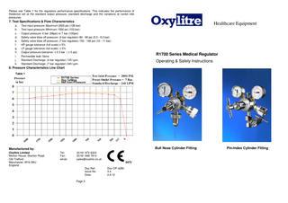
Bull Nose Cylinder Fitting
Manufactured by: Oxylitre Limited Morton House, Skerton Road Old Trafford Manchester, M16 0WJ England
Tel: Fax: email:
(0)161 872 6322 (0)161 848 7914 [email protected] 0473 Doc Ref: Issue No: Date: Page 3
Doc-OP-4280 3.4 4.9.12
Pin-Index Cylinder Fitting
1. Introduction The Oxylitre R1700 series twin gauge regulator is designed specifically for medical use. It is available in pre-set or adjustable models for: Oxygen, Nitrous Oxide, Helium, Medical Air, (4 or 7 Bar) & Carbon Dioxide. Conforms to BS EN ISO 10524-1.
2. Specifications Inlet Connection All gas connections comply with National & International Standards for safety prevention of connecting a incorrect gas (BS 341-3 for Bull Nose; BS EN ISO 407 for Pin Index). Outlet Connection All models are available with a gas specific self-sealing valve or a 3/8 bsp outlet fitting which is suitable for most piped connections. Outlet Pressure The regulator is available with a pre set setting or a manual adjustable control key. Models are available in pre set or adjustable units for output pressure of up to 4 Bar (58 psi) or 7 Bar (100 psi). The Medical Air 7 Bar models may be used for driving special Air Tools etc. (see specifications & technical data for suitability) Filters (Please note: Filters should only be replaced by authorised/trained personnel) The regulator is fitted with two integral filters that protect the unit from any foreign matter. 1. The first filter is placed in the inlet stem of the regulator. 2. The second filter is placed in the self-sealing valve assembly. Contents Gauge The regulator is fitted with an easy to read, colour coded contents gauge. A safety system is placed in the rear of the gauge, which releases gas pressure in the event of a leak. Low Pressure Gauge The second gauge is the low pressure gauge that is for the purpose of indicating the amount of pressure that is to be delivered to the output. Safety Valve The safety valve system has been designed to release gas pressure for the safety of the user/patient and/or the equipment connected to the regulator. This will operate only if the output pressure increases due to a malfunction in the regulator. (This safety valve system is not an adjustable device)
3. Instructions for use Fitting to a Cylinder (Note: Take great care with these operations): Before connecting a Regulator to a Cylinder, momentarily open and close the Cylinder Valve to blow out any accumulated dust or moisture. Inspect the inlet connector seal for signs of damage or contamination, if found replace immediately! These seals should be replaced at least once a year i.e. as part of a Standard Service (Note: NEVER use two seals together). Seal for Pin Index Inlet Connectors = Part No: OX010 (BODOK) Seal for Bull Nose Inlet Connectors = Part No: BS110 (‘O’ Ring) Seal for CO2 Nut System = SB09A Connect the regulator to the cylinder. Always open the valve very slowly (approx one full turn) to reduce the danger of explosion or fire arising from pressure shock.
If the regulator is an adjustable model with a gas specific self-sealing valve, turn the adjuster key clockwise until the required pressure is indicated on the low pressure gauge. (not required on pre set)If the regulator is an adjustable model with a 3/8 bsp outlet, ensure that the equipment being used has been connected to the regulator outlet securely. Then turn the adjuster key clockwise until the required pressure is indicated on the low pressure gauge. Removing from a Cylinder a. Turn OFF the cylinder valve. b. Bleed off the pressure, by opening a valve on the apparatus connected to the regulator. c. Disengage the regulator from the cylinder.
4. Safety Precautions for the prevention of Fire & Explosion The Regulator or patient MUST NOT be allowed near any source of ignition i.e.: Cigarette/cigar/pipe smokers Sparks Naked flame Open electrical appliances This precaution applies during and after patient use. Warning: This Regulator MUST NOT come into contact with any Oil or Grease, a reaction may cause an Explosion/Fire.
5. Maintenance A medical regulator forms part of an essential support system. Regulators must be treated with care and be serviced on a regular basis, (i.e. preventative maintenance) to ensure the unit’s reliability and quality for the purpose that it is used for. The units require cleaning on external surfaces only by using a solution of luke-warm water and “Dettol” or similar disinfectant fluid (read disinfectant instructions) and cleaning cloth. Inspection Recommended at least annually by a Service Engineer and consist of: a. Connect regulator to the cylinder (as in section 3) b. Check the contents of the cylinder that is indicated by the pressure gauge. c. Close the cylinder valve and observe the contents gauge for pressure drop. If the needle on the gauge drops, this indicates a leakage in the system. The device will require a service and/or repair (note: connected equipment may leak, please disconnect this prior to testing the regulator. Also adjustable regulators may require adjustment during use). Service/Repair Servicing should be only carried out by fully qualified technicians. A Major Service is recommended every 5 years. For service enquiries and information, please contact our sales office. NEVER USE FAULTY EQUIPMENT. Preventative maintenance ensures safety for the patient and user.
6. Technical Data Specifications a. Maximum inlet pressure: 2000 psi (138 bar) b. Minimum inlet pressure: 400 psi (27.6 bar) c. Output pressure: 58 psi (4 bar) & 100 psi (7 bar) Nominal d. Standard discharge: 240 Lpm
Before use, check the contents of the cylinder indicated on the pressure gauge.
Page 1
Page 2