Quick Guide
8 Pages
Preview
Page 1
QUICK GUIDE MPR2 logO DATALOGGER Quick Guide is not a replacement for Instructions For Use! For detailed instructions refer to the MPR2 logO DATALOGGER and NEUROVENT-PTO IFU.
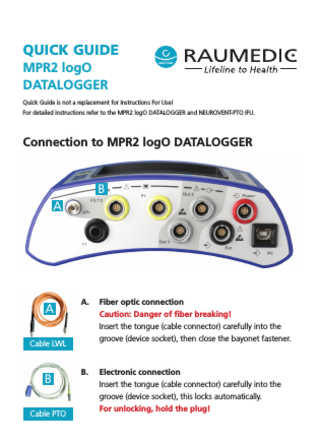
Connection to MPR2 logO DATALOGGER
B A
A
A.
Fiber optic connection Caution: Danger of fiber breaking! Insert the tongue (cable connector) carefully into the groove (device socket), then close the bayonet fastener.
B.
Electronic connection Insert the tongue (cable connector) carefully into the groove (device socket), this locks automatically. For unlocking, hold the plug!
Cable LWL
B Cable PTO
Catheter Connections Connection between catheter and Cable LWL Step 1: Insert the tongue into the groove
Tongue
Groove
Step 2: Turn the connector until it locks
90°
Tongue Groove
Locked Connection
Connection between catheter and Cable PTO
Device Settings 1
Confirm the new patient from the selection with 'OK'. Alternatively the selection field Continue measurement can be confirmed via "Menu" with 'OK'
2
2
Select the storage mode using the arrow buttons and confirm with 'OK'.
Alternatives: ÆÆ Trend + curves (100 Hz) ÆÆ Trend (1 Hz) ÆÆ No storage
3
Select the alarm limit via 'Cur' and 'Std'. Cur: The last setting is applied. Std: The manufacturer setting is applied.
3
Connection to Patient Monitor 1
Select 'ICP2' as the signal.
2
Select the Output 'Out2'.
3
Connect the Cable DATALOGGER to the patient monitor.
4
Confirm the connection by pressing the 'OK' button.
C
C
(ICP2 = Out2 / pO2 = Out1)
For unlocking, hold the plug!
4
5
Now perform the zeroing on the patient monitor.
6
As soon as 0 mmHg appears on the patient monitor, press 'OK'.
7
Check the reference pressure on the patient monitor. As soon as 100 mmHg ± 2 mmHg appears on the patient monitor, confirm this with 'OK'.
8
For the forwarding of the pO2 value, repeat the steps. For the output in step 2 select 'Out1'.
5
Complications Device memory ÆÆ In the event of capacity problems, a notification window will open. ÆÆ Confirm this with 'OK'. ÆÆ Back up the data on the PC.
ÆÆ The device memory can be deleted afterwards by pressing 'Del'. ÆÆ Follow the instructions.
Sensor messages
6
ÆÆ When sensor messages occur, press 'Info' to obtain more detailed information. ÆÆ If the cause cannot be remedied, switch off the measuring channel.
Æ If the cause is too low amplitude (below 375), clean the following optical connections very carefully: – on the Cable LWL (A) – on the connection socket of the Cable LWL (A) – on the connection socket (A) of the MPR2 logO DATALOGGER – on the catheter When cleaning the connections, use a thin short-hair brush and medical alcohol. Switching off measuring channels Æ In the event of a sensor failure, the measuring channel can be switched off via the 'ICP2' or 'T2' button. Æ Press ICP2 or T2 and navigate to 'Use channel', select 'No' and confirm with 'OK'.
Æ In the event of a sensor failure, the measuring channel can be switched off via the 'pO2' button. Æ Open pO2 for each measuring interval, select 'off' and confirm with 'OK'.
7
Cable connection (from FW version 2.00.0061)
ÆÆ If the message appears only on the Multiport (P2/T2), use the Cable PTO when carrying out a pO2 measurement. ÆÆ Close the information window by pressing 'OK'.
Graphic display ÆÆ Use the arrow button to switch to the graphic display. You can switch between the following screens:
International Contact: RAUMEDIC AG Herrmann-Staudinger-Str. 2 D - 95233 Helmbrechts, Germany www.RAUMEDIC.com/hospitalcare
Tel: +49 9252 359 0 Fax: +49 9252 359 51 3333 [email protected]
zwo-442EN Rev.0
1 Numeric display (current view) 2 Live data 3 Trend data 4 Device settings