Operating Manual
60 Pages
Preview
Page 1
Letzte Änderung: Monday, 4. July 2005 10:16
Operating manual Operating table OPX mobilis
This operating manual includes instructions for the operation of the mobile operating tables – – – – – – – – – –
2
OPX mobilis 200 (161.201) OPX mobilis 200/G (161.205) OPX mobilis 300 C (161.311) OPX mobilis 300 C/G (161.315) OPX mobilis 300 CL (161.321) OPX mobilis 300 CL/G (161.325) OPX mobilis 300 CE (161.331) OPX mobilis 300 CE/G (161.335) OPX mobilis 300 CLE (161.341) OPX mobilis 300 CLE/G (161.345)
Operating manual
Contents Introduction... 5 About this operating manual... 5 Symbols used in the text... 6 Safety instructions... 7 Intended use... 7 Summary of safety instructions... 8 Description of the operating table... 11 Commissioning... 13 Keeping... 13 Transportation... 13 Unpacking... 13 Electrical connection... 14 Operation... 15 Mobility... 15 Potential equalization socket... 17 Battery... 18 Battery charger... 19 Adjusting the table-top... 21 Longitudinal shift function of the table-top... 25 Integrated kidney bridge... 27 Leg plates... 29 Head plate... 31 Back section... 33 Arm rest 101.107... 34 Add-on kidney bridge... 35 Shoulder arthroscopy support... 36 Accessories for urology... 40 Further accessories of the Schmitz range... 42 Cleaning and disinfection... 43 Cleaning... 43 Disinfection... 44
Operating table OPX mobilis –
EDITION 01-05-GB
ID.-Nr.: 02007844
3
Contents
Check-ups... 45 Electromagnetic Compatibility (EMC)... 47 Electromagnetic Emissions... 47 Electromagnetic Immunity... 48 Electromagnetic Immunity for Non-Life Supporting Equipment... 49 Separation distance... 50 Malfunctions and repairs... 51 Disposal... 51 Spare parts... 53 Product designation... 54 Nameplates... 54 Symbols employed on the product... 55 Technical data... 56 Classification... 58 Standards applied... 58 Declaration of Conformity... 59 After sales service... 60
4
Operating manual
Introduction About this operating manual In case of any questions, we therefore kindly ask you to contact Schmitz u. Söhne.
In this paragraph you will find information about the layout of this operating manual and explanations regarding the marks and symbols used. This operating manual includes instructions for the use of the operating tables OPX mobilis, also called operating tables in the following. Our products are constantly being improved, this is why constructional changes carried out after printing of this operating manual could not be taken into consideration.
Operating table OPX mobilis –
EDITION 01-05-GB
This operating manual is to be read and observed by any person using or handling the operating tables OPX mobilis. In addition to the operating manual and to the obligatory regulations for the prevention of accidents effective in the user’s country and on the site of use, the acknowledged rules for safe and professional work are also to be observed.
ID.-Nr.: 02007844
5
Introduction
Symbols used in the text In this operating manual following designations or signs are used for pieces of information of special importance
g v a
6
Danger! This symbol will appear wherever safety instructions are designed to protect people from physical harm. The symbol stands for imminent danger of death or serious injury.
Caution! This symbol will appear where situations are described, which might be dangerous, and which might inflict slight injuries.
h
This symbol will appear in front of additional helpful pieces of advice.
• A dot in front of the text means: This is what you have got to do.
– A dash in front of the text means: This is part of a listing.
Attention! This symbol will appear in front of such hints which shall prevent the table or other equipment from being damaged.
Operating manual
Safety instructions The operating table OPX mobilis has been constructed according to the latest state of engineering and according to the acknowledged rules of safety engineering. Nevertheless, its use may inflict danger to life or physical safety of the user or of third parties, or impairment to the operating table or to other material assets.
Always keep this operating manual at hand at the site of use of the operating table!
Do not use the operating table unless in perfect condition and only for its intended use, with regard to safety and possible dangers, and observing the operating manual! Any malfunction which may affect the safety has to be eliminated immediately!
Do not carry out any modifications, extensions or reconstructions of the operating table unless approved by the manufacturer.
Electrically conductive double castors, electrically conductive pads and a potential equalization socket are standard features of the operating table OPX mobilis. It may be used inside rooms where the electrical installation conforms to German VDE (i. e. the Association of German Electrical Engineers) 0100-710 standard or to an equivalent national standard. If the operating table OPX mobilis is equipped with non-electrically conductive (coloured) pads, it must not be used in the presence of flammable anaesthetic mixtures.
Additionally to the operating manual, observe the general rules implied by the law and otherwise obligatory for accident prevention and environmental protection!
Spare parts have to meet the requirements stipulated by the manufacturer. This is always guaranteed when using original spare parts. Observe the intervals prescribed or stated in this operating manual for periodical check-ups! Take care that running and process materials as well as parts replaced are disposed of safely and with minimum environmental impact!
Intended use According to German VDE 0100-710 standard, the operating table OPX mobilis may be used inside rooms of the application groups 0, 1 or 2. It is exclusively designed for purposes of human medicine. The operating table serves to position patients during an examination or during surgical interventions. The nursing staff has to take care to position the patients in such a way as to prevent any danger to their respiration, to their nervous system or to their circulation. This is especially important when patients are under anaesthetics. Any use apart or beyond these purposes is not intended. The manufacturer is not
Operating table OPX mobilis –
EDITION 01-05-GB
liable for any damage resulting of such non-intended use, which would be entirely at the user’s risk. The operating table may only be handled by persons who have been briefed in its professional handling and who have familiarized themselves with the product by means of this operating manual. Intended use also means following the operating manual and observing the conditions for inspection and maintenance.
ID.-Nr.: 02007844
7
Introduction
Summary of safety instructions
g g g g g g
8
Danger! Operating tables with an “E” in their type designation are equipped with rechargeable batteries. Do not charge the batteries during a surgical intervention inside the operating theatre.
Danger! Patients run the risk of falling off the operating table unless they are secured on the table-top. Patients lying on the operating table have to be secured to the table-top according to professional standards.
Danger! Patients run the risk of getting hurt when the operating table is moved while he or she is lying on top in knee-elbow-position. Do not move the table with the patient in knee-elbowposition.
Danger! Patients run the risk of getting hurt if the operating table is moved with an attached extension device, due to its diminished stability against tilting. Do not move the operating table with an attached extension device when a patient is lying on top.
Danger! If an extension device is attached to the operating table, its stability against tilting will be diminished. Always use the props of the extension device during an operation.
Danger! If patients are not positioned correctly, there may be danger to their respiration, to their nerve cords or to their circulation. Always position patients in such a way as to prevent any possible danger to their respiration, to their nerve cords or to their circulation.
g g g g g
Danger! In case the components of the table-top hit against an obstacle during adjustment, the operating table may tilt. Remove possible obstacles before adjusting the operating table or its individual components. When folding the leg plate down, make sure it cannot hit the floor.
Danger! If its castors are released, the operating table may move unintentionally during patient transfer. Always secure the operating table by means of the central brake before transferring the patient.
Danger! Patients run the risk of getting hurt by unforeseen movements of the table accessories. When attaching accessories, make sure that they are properly fixed. Do not use worn or damaged accessories.
Danger! Patients run the risk of getting hurt by unforeseen movements of the operating table. Always secure the patient to the table-top according to the recommended practices of patient positioning.
Danger! When HF surgical equipment or defibrillators are being used, there is danger of the patient’s suffering burns if he or she touches the metal parts of the operating table or of its accessories, or if he or she is lying on soaked sheets or cloths covering the electrically conductive pads of the table-top. Always observe the manufacturer’s instructions for use.
Operating manual
g g v v v v
Danger! Patients run the risk of getting hurt if the longitudinal shift function is released with the table positioned in Trendelenburg or Reverse Trendelenburg angle of more than 5°. Reduce the inclination angle of the table-top before activating the longitudinal shift function.
Danger! If the operating table OPX mobilis is used in the presence of flammable anaesthetic mixtures, the floor must be electrically conductive.
g h
Caution! The operating table is only stable on a level floor. Choose a horizontal and safe site of installation for the operating table.
Danger! For tables with longitudinal shift feature, the position of the table-top will bear influence on the stability of the operating table. Always shift the table-top into such a position, within the limits of the specific application, as to improve the stability of the table.
If there is an extension device attached to the table or if the patient is positioned in kneeelbow position, the stability of the table will be diminished. Improve the stability of the table by moving the table into such a position as to make the double castors at the foot end of the table point to the foot end.
Caution! In case the table-top is adjusted into extreme positions, there is danger of jamming one’s finger in certain points. Do not grab below the operating table or behind the frames of the table-top elements.
Caution! In order to ensure a gentle patient positioning when using the add-on kidney bridge, use an additional pad on top of the break. (This pad comes together with the add-on kidney bridge.)
Caution! If the operating table is positioned on a moist or freshly cleaned floor, please keep in mind that the frictional forces will be diminished. The operating table may therefore be moved by external force even if the double castors are blocked. Make sure before starting an intervention that the operating table is in a sufficiently stable position.
Operating table OPX mobilis –
EDITION 01-05-GB
ID.-Nr.: 02007844
9
Introduction
h h h
10
An unfavourable position of the double castors may diminish the stability of the table. It may help to move the operating table in such a way as to raise the stability. Please see the examples given in the illustration.
A patient weight of max. 135 kg allows all surgical interventions to be carried out in either orientation of the patient (patient’s head lying at head or foot end of the table), provided the castors of the operating table are blocked.
In the case of normal patient orientation and table-top in mid-position (for operating tables with longitudinal shift function) the operating table may be charged with a patient weight of max. 185 kg. Upon patient transfer, or when letting the patient mount the operating table, make sure that the table-top is loaded mainly above the table column. Familiarize yourself with the reactions of the operating table under this kind of charge before starting a surgical intervention.
Operating manual
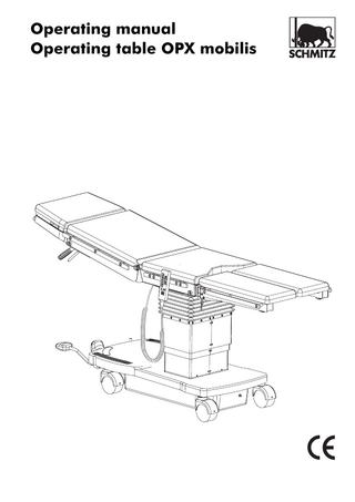
Description of the operating table
Head plate
Back section
Seat section
Leg plate
Foot pump lever Pedal for brake and for directional castor Selector lever
Potential equalization socket
Control panel for electric version
Double castor
In the following operating manual the terms left, right, front, and rear are used as seen by a person sitting on the operating table in normal position.
Operating table OPX mobilis –
EDITION 01-05-GB
ID.-Nr.: 02007844
11
Description of the operating table
The operating tables OPX mobilis can be equipped differently, depending on the model. All operating tables are mobile. They are equipped with four electrically conductive swivel-type double castors with central brake. The operating table models with a “C” in their type designation have got an additional directional castor. All operating tables are equipped with mechanically operated hydraulic pumps. The operating table of the 200 model series have got two hydraulic adjustment functions: Height adjustment Raise/Lower and Trendelenburg/Reverse Trendelenburg. The tables of the 300 model series have got an additional lateral adjustment function. Operating tables with an “E” in their type designation are equipped with an additional electrically-driven hydraulic pump. In this case the operating table is equipped with a hand-held remote control unit as well, and with rechargeable batteries installed inside the floor pan. Operating tables with an “L” in their type designation are equipped with a table-top with longitudinal shift function. By means of this feature, such parts of the patient’s body can be screened which under normal circumstances are inaccessible to the C-arm equipment. Operating tables with a “G” in their type designation are equipped with an integrated kidney bridge. The integrated kidney bridge is adjusted hydraulically by means of the foot pump.
h h
A patient weight of max. 135 kg allows all surgical interventions to be carried out in either orientation of the patient (patient’s head lying at head or foot end of the table), provided the castors of the operating table are blocked.
In the case of normal patient orientation and table-top in mid-position (for operating tables with longitudinal shift function) the operating table may be charged with a patient weight of max. 185 kg. Upon patient transfer, or when letting the patient mount the operating table, make sure that the table-top is loaded mainly above the table column. Familiarize yourself with the reactions of the operating table under this kind of charge before starting a surgical intervention.
Pads The operating tables are normally equipped with black antistatic pads. Coloured pads, which, however, are not electrically conductive, are available upon special request. The antistatic black version fulfils the limits of resistance according to ISO 2882. Coloured pads are not electrically conductive, which means that in this case the operating table is not explosion-proof.
Safety devices All operating tables can be equipped with X-ray cassettes, which can be inserted below the table-top either from the head end or from the foot end. All operating tables can be adapted optimally to various applications by means of accessories.
All operating tables are equipped with electrically conductive swivel-type double castors, with (normally) electrically conductive pads, and with a potential equalization socket.
According to the regulations of European Standard 60601-2-46, the operating tables are designed to carry a maximum patient weight of 135kg. In case a higher charge is intended, please observe the instructions given below.
12
Operating manual
Commissioning Keeping Inside its original packing the operating table may be exposed for a period of 15 weeks to environmental conditions within the limits of:
Ambient temperature
-5°C to +50°C
Relative atmospheric humidity
10% to 95%
Atmospheric pressure
500 hPa to 1,060 hPa
Transportation • In order to transport the operating table, adjust seat and back section into horizontal position. • Remove head and leg plates, and detach other accessories. • Adjust the table-top into minimum height.
Upon leaving the factory, the operating tables are positioned fit for transportation. In case of further transportation at a later date, we recommend to adjust the operating table into the same positions.
Unpacking Carry the operating table, if possible, in its original packing to its final site of use. Check the operating table’s condition. Any possible damage occurred during transportation should be reported immediately to Schmitz u. Söhne. You will find their address and telephone no. on the last page of this operating manual.
Operating table OPX mobilis –
EDITION 01-05-GB
ID.-Nr.: 02007844
13
Commissioning
Electrical connection The operating table can be equipped with an electrically driven hydraulic pump. In that case it is also equipped with a hand-held remote control unit activating the electro-hydraulic pump. The hydraulic pump draws its energy from the integrated batteries. If the main switch is switched on, the battery state is indicated by means of the LEDs at the hand-held remote control unit.
• In order to connect the hand-held remote control unit to the table, insert the plug into the socket, with the marking dots in alignment, and plug the plug into the socket until it locks. • In order to disengage the hand-held control unit, draw the front part of the plug back. Then pull the plug out of the socket. Operating tables with an “E” in their type designation are equipped with rechargeable batteries.
Hand-held remote control unit Batteries Operating tables with an “E” in their type designation are equipped with an electro-hydraulic pump and a handheld remote control unit. The hand-held remote control is connected to the operating table OPX mobilis by means of a plug-type connector. You will find the connector socket for the handheld remote control unit at the top of the height adjustment column. The connector plug and socket are marked by dots. The plug will lock inside the socket when the relative dots are brought into alignment.
The batteries have to be recharged as soon as the yellow LED on the remote control unit is on. You will find details how to charge the batteries under “Charging the batteries” on page 18. The electric drive of the hydraulic pump can be activated additionally by means of the main switch. You will find the main switch on the control panel at the left hand side of the floor pan.
h
The table-top of the operating table can always be adjusted mechanically, without electric drive, by means of the foot pump.
Marking dots
• The electrically driven hydraulic pump of the operating tables with an “E” in their type designation has to be activated by means of the main switch.
14
Operating manual
Operation
v
Mobility Depending on the model, the operating tables OPX mobilis can equipped in different ways. All operating tables are mobile. Depending on the model, they are either equipped with – four double castors with central brake – four double castors with central brake and an additional directional castor.
Caution! If the operating table is positioned on a moist or freshly cleaned floor, please keep in mind that the frictional forces will be diminished. The operating table may therefore be moved by external force even if the double castors are blocked. Make sure before starting an intervention that the operating table is in a sufficiently stable position.
Moving and locking the operating table
g
Danger! Patients run the risk of falling off the operating table unless they are secured on the table-top. Secure the patient to the table-top according to professional standards.
• Move the table into the desired position and then turn the castors outwards in order to improve the stability of the operating table.
h
The position of the castors will bear influence on the stability of the operating table.
Operating table OPX mobilis –
EDITION 01-05-GB
ID.-Nr.: 02007844
15
Operation
The operating tables, except the standard model, are equipped with an additional directional castor. The directional castor can be activated by means of a foot pedal for the brake and for the directional castor.
g
Selector lever
Pedal for brake and for directional castor
Foot pump lever
The pedal for the brake and for the directional castor can have three different positions. – If the pedal is raised, the operating table will move in straight run. An additional directional castor
16
positioned below the height adjustment column is now touching the ground. – If the pedal is in mid position, the operating table can easily be moved in any direction. The directional castor is retracted. – If the pedal is pressed down, the operating table is secured against unintentional movement.
g
Danger! Patients run the risk of getting hurt when the operating table is moved while they are lying on top in knee-elbow-position. Do not move the table with a patient lying on top in knee-elbowposition.
Danger! Patients run the risk of getting hurt if the operating table is moved with an attached extension device, due to its diminished stability against tilting. Do not move the operating table with an attached extension device when a patient is lying on top.
• In order to move the operating table in straight run, raise the pedal completely. • In order to move the operating table easily in any desired direction, raise the pedal into mid-position. • Move the operating table into the desired location. • Secure the operating table afterwards by pressing the pedal completely down.
Operating manual
Potential equalization socket The operating table is equipped with a potential equalization socket. You will find the potential equalization socket at the front side of the floor pan.
g
Danger! Patients may be exposed to danger by electrostatic tensions. By means of the potential equalization socket electrostatic tensions are conducted to earth. Always connect the potential equalization socket of the operating table to earth before use.
• Before putting the operating table into operation, connect the potential equalization socket to the earth connection.
Operating table OPX mobilis –
EDITION 01-05-GB
ID.-Nr.: 02007844
17
Operation
Battery If the operating table is equipped with an electrohydraulic pump, this pump draws its energy from batteries installed inside the floor pan. The batteries have to be recharged regularly in order to avoid an exhaustive discharge.
g
Danger! Plugging the plug of the charging cable in or out may produce sparks. In order to avoid danger of explosion, the batteries must not be charged inside the operating theatre during surgical interventions.
The yellow LED will be on as soon as the batteries have to be recharged. When the red LED is on, the electrohydraulic pump can no longer be activated before the batteries have been recharged. • If the red LED is on, switch the main switch at the control panel off, use the foot pump in order to adjust the table-top until the operation is finished, and recharge the batteries afterwards.
Fuse F2 = 3.15A
Charging the batteries
h a
The batteries should be recharged regularly, e. g. overnight. The batteries cannot be overcharged if you use the battery charger which comes with the table.
Charging socket
Attention! If the batteries of the operating table are charged by means of a battery charger other than the one supplied with the table, the batteries may get damaged. Always use the original battery charger for charging the batteries.
The hand-held remote control unit is equipped with LEDs. The green LED is on when the batteries are fully charged.
18
Fuse F1 = 10A
h
Main switch
The fuses for the electro-hydraulic pump (F1 = 10 A, time lag type, 5 x 20 mm) and for the charging current (F2 = 3.15 A, time lag type, 5 x 20 mm) are also inserted into the control panel.
Operating manual
Battery charger The battery charger is fit for a voltage input of between 90V to 264V. It can be equipped with the feed cable corresponding to the requirements on site.
LED, green, yellow or orange-coloured
• In order to charge the batteries, move the operating table out of the operating area.
h h
The batteries cannot be charged as long as the main switch is on.
The charging current is up to 2A. Make sure that the correct fine-wire fuse (3.15A, slowblow type) has been installed inside the fuse holder F2 for charging current. This is especially important for the more ancient models of the OPX mobilis range.
• Switch the main switch at the control panel off. The charging cable of the battery charger is connected to the operating table by means of a plug contact. You will find the socket for the battery charger at the control panel at the left hand side of the floor pan. The plug and the charging socket are marked by dots. The plug will lock inside the charging socket if it is plugged into the charging socket with the dots in alignment.
h
The operating modes of the battery charger are indicated by means of a 3-coloured LED.
Charging diagram Charging voltage
The control panel is equipped with a covering sheet, which is designed to protect the control electronics against electrostatic discharge current. Fold this covering sheet up in order to get access to the control panel.
Voltage (V) Rapid charge Charge LED=orange LED=yellow Electric current (A)
• Plug the plug of the battery charger into the charging socket so that the marking dots are in alignment and press the plug in until it locks inside the charging socket. • Connect the battery charger to the mains power supply.
Operating table OPX mobilis –
EDITION 01-05-GB
ID.-Nr.: 02007844
Compensation charge LED=green
Charging current Capacity
19
Operation
If the batteries are drained, it will take approx. 8 to 10 hours to recharge them. The batteries are charged as soon as the LED is green. The battery charger can then be disconnected. • In order to detach the charging cable, pull the front part of the plug back and pull the plug out of the socket. Now the table-top can again be adjusted with the aid of the electro-hydraulic pump.
h
20
With fully charged, practically new batteries, the table can carry out all its functions approx. 60 times when charged by a patient weight.
Operating manual