Service Manual
286 Pages
Preview
Page 1
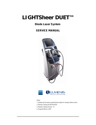
LIGHTSheer DUET™ Diode Laser System SERVICE MANUAL
Notes: 1. System and Accessory specifications subject to change without notice. 2. Manual Catalog No.SM-0035630 3. Manual Catalog Version “A” 4. Prepared March, 2009
© Copyright 2009 by the Lumenis group of companies. All rights reserved.
Lumenis, the Lumenis logo, LightSheer, and the LightSheer logo are trademarks or registered trademarks of the Lumenis group of companies. LightSheer, the LightSheer logo, ChillTip, OptiPulse, AutoPace, Lumenis, and the Lumenis logo are trademarks or registered trademarks of the Lumenis group of companies.Cavicide® is the property of Metrex Research Corporation.Virex™ is the property of S.C.Johnson Commercial Markets, Inc. This manual is copyrighted with all rights reserved. Under the copyright laws, this manual cannot be copied in whole or in part without the express written permission of Lumenis, Inc. Permitted copies must carry the same proprietary and copyright notices as were affixed to the original. Please note that while every effort has been made to ensure that the data given is accurate, the information, figures, illustrations, tables, specifications, and schematics are subject to change without notice. Caution: U.S. law restricts this device to sale by or on the order of a physician.
Use of Manual: The LIGHTSheer DUET™ diode laser system is designed to meet international safety and performance standards. Personnel operating or servicing the system must have a thorough understanding of the proper operation of the system. This manual has been prepared to aid Lumenis-authorized technical personnel to understand and service the system. Do not operate the system before reading this manual and gaining a clear understanding of the operation of the system.
ii
Regulatory European Representative: Lumenis (Germany) GmbH Heinrich-Hertz-Strasse 3 D-63303 Dreieich Germany
iii
DISCLAIMER
Lumenis service manuals are written specifically for use by Lumenis service engineers and trained representatives who have received formal training in the servicing of Lumenis equipment, and by customers who have taken and passed a Lumenis certification training course for the equipment being serviced. Information on certification training courses offered to system owners can be obtained by contacting the Customer Service Department at Lumenis.
Lumenis does not accept responsibility for personal injury or property damage resulting form the servicing of Lumenis equipment by its customers or by third parties, except where such injury or property damage is a direct result of Lumenis' negligence. Customers, by accepting the service manual, agree to indemnify Lumenis against any claims alleging personal injury or property damage resulting from the servicing of Lumenis equipment by the customer or by third parties, except where such injury or property damage is a direct result of Lumenis' negligence. These limitations include situations where Lumenis personnel are advising customers on the repair of Lumenis equipment over the telephone.
The servicing of Lumenis equipment by persons who have not passed a Lumenis certification training course for that equipment will void Lumenis' product warranty.
iv
PHYSICIAN RESPONSIBILITY Federal (USA) law restricts prescription medical devices to sale by or on the order of a physician, or properly licensed practitioner. That physician will be responsible for the use and operation of the device and for all user qualifications. Lumenis makes no representations regarding federal, state or local laws or regulations that might apply to the use and operation of any medical device. The physician is responsible for contacting his or her local licensing agencies to determine any credentials required by law for clinical use and operation of the device.
MAINTENANCE The LIGHTSheer DUET™ diode laser system is a precision, technical medical device that requires routine service as well as consumable parts. All service must be performed by a Lumenis technician and all parts must be purchased from Lumenis. Failure to obtain service and parts through Lumenis voids all warranties, express and implied. Please call Lumenis or your local representative for details.
MODIFICATION OF DEVICE Unauthorized modification of the hardware, software or specifications of the system voids all warranties, express and implied. Lumenis takes no responsibility for the use or operation of such a device.
RESALE INSPECTION The LIGHTSheer DUET™ diode laser system is a precision, technical medical device. If any Lumenis device is resold by anyone other than an authorized sales representative, Lumenis offers a resale inspection by a Lumenis technician to assure that the device is working in accordance with manufacturer's specifications. Using the device after it has been resold and before it has been inspected is a misuse of the device, which may result in injuries and voids all warranties, express and implied.
RELEVANT DOCUMENTS LIGHTSheer DUET™ diode laser system Operator's Manual (P/N # PB-005755)
v
Publication No.
Revision
Description
Date
SM-0035630-00
0
Draft Release
May, 2007
SM-0035630
A
First Release
March 2009
vi
TABLE OF CONTENTS Chapter 1: Introduction 1.1 Scope of Manual ... 1-1 1.2 Applicable Documents... 1-3 1.3 Conventions, Terms, and Abbreviations ... 1-3 1.3.1 1.3.2 1.3.3 1.3.4
Manual Conventions...1-3 Serial Number Format...1-4 Terms and Definitions ...1-4 Acronyms, and Abbreviations...1-6
Chapter 2: Safety and Regulatory 2.1 Introduction... 2-1 2.1.1 The Treatment Room ...2-3
2.2 Major Precautions, Cautions and Warnings ... 2-3 2.2.1 Precautions...2-4 2.2.2 Cautions...2-4 2.2.3 Warnings Related to Laser Emission ...2-4
2.3 Optical Safety ... 2-5 2.3.1 General...2-5 2.3.2 Eye Protection ...2-6 2.3.3 Other Ocular Safety Considerations ...2-7
2.4 Electrical and Mechanical Safety ... 2-7 2.5 Fire and Burn Hazards ... 2-8 2.6 Chemical Hazards... 2-8 2.7 System Safety Features... 2-8 2.7.1 2.7.2 2.7.3 2.7.4 2.7.5 2.7.6 2.7.7 2.7.8
Keyswitch...2-8 Safety Interlocks ...2-9 Audible Emission Indicator ...2-9 Handpiece Enable ...2-10 Electronic Shutter...2-10 Handpiece Trigger ...2-11 Emergency Stop Switch ...2-11 Handpiece Design ...2-12
2.8 Operating Precautions... 2-12 SM-0035630 Rev. A
vii
LIGHTSheer DUETTM Service Manual
2.9 Labels... 2-13 2.9.1 System Labels ...2-13 2.9.2 Treatment Head Labels ...2-17
2.10 Regulatory Compliance ... 2-18 2.10.1 Equipment Classification ...2-19
Chapter 3: General Description 3.1 Introduction... 3-1 3.1.1 Indications for Use ...3-2 3.1.2 Theory of Operation ...3-3
3.2 LIGHTSheer DUET External Components... 3-3 3.3 Handpieces... 3-5 3.3.1 3.3.2 3.3.3 3.3.4 3.3.5
HS Handpiece...3-5 ET Handpiece ...3-7 External door interlock ...3-9 USB port ...3-10 RJ-45 Ethernet Port...3-11
3.4 Technical Specifications... 3-12
Chapter 4: Site Preparation 4.1 Facility Requirements... 4-1 4.1.1 Space Requirements ...4-1 4.1.2 Electrical Requirements ...4-3 4.1.3 Environmental Requirements ...4-3
4.2 Remote Interlock Connection ... 4-4 4.2.1 Remote Interlock Switch Installation ...4-4
Chapter 5: Installation 5.1 Introduction... 5-1 5.2 Inspection... 5-1 5.3 Unpacking the System ... 5-1 5.3.1 Installing the Holsters ...5-3 5.3.2 Attaching the Handpieces to the Laser...5-5 5.3.3 Installation and First-Time Setup...5-8
5.4 System Operation... 5-10 5.4.1 Preoperative instructions ...5-10
viii
SM-0035630 Rev. A
5.4.2 5.4.3 5.4.4 5.4.5 5.4.6 5.4.7
Operational and Safety Check...5-11 Turning on the Laser - Basic User Operation...5-13 Laser Calibration ...5-17 Calibrating the Handpieces...5-18 Turning off the Laser...5-25 Emergency Stop ...5-26
5.5 Return Shipping ... 5-27 5.6 Disconnecting and Storing the Laser Components... 5-27 5.7 Installation Check List... 5-29 5.7.1 Space Requirements (Section 4.1.1) ...5-29 5.7.2 Electrical Requirements (Section 4.1.2)...5-29 5.7.3 Environmental Requirements (Section 4.1.3.)...5-29 5.7.4 Installation...5-30
Chapter 6: Functional Description 6.1 Introduction... 6-1 6.2 Main Block Diagram ... 6-3 6.2.1 6.2.2 6.2.3 6.2.4
Power Supply...6-4 Base Board and System Controller PCB...6-12 Driver Board ...6-17 GUI Controller PCB ...6-21
6.3 Cooling System... 6-26 6.3.1 6.3.2 6.3.3 6.3.4
Heat Exchange SubSystem ...6-26 Cooling Pump...6-29 Vacuum Subsystem ...6-29 ET & HS Handpiece & Power Detector Assembly ...6-33
6.4 System Software - User Screens... 6-41 6.4.1 Main Screen...6-41 6.4.2 Handpiece Selection ...6-42 6.4.3 Laser Calibration ...6-42 6.4.4 Treatment Screen Common Functions ...6-46 6.4.5 Pulse Counter Field...6-47 6.4.6 Selecting the Laser Mode: Ready or Standby ...6-48 6.4.7 HS Handpiece Treatment Screen ...6-48 6.4.8 Save as User Preset Screen ...6-51 6.4.9 Clinical Indications Screen - HS ...6-51 6.4.10 ET Handpiece Treatment Screen...6-51 6.4.11 Save as User Preset Screen ...6-54 6.4.12 Clinical Indications Screen -ET ...6-55
6.5 System Software - Service Screens ... 6-56
SM-0035630 Rev. A
ix
LIGHTSheer DUETTM Service Manual
6.5.1 Utility Menu...6-56 6.5.2 Service Screens...6-64 6.5.3 Access to Service Screens...6-65 6.5.4 HS Diagnostic screen ...6-67 6.5.5 Service ET Diagnostic Screen ...6-74 6.5.6 Power Detector Setup...6-81 6.5.7 Service HS Setup Screen...6-81 6.5.8 Service ET Setup Screen...6-84 6.5.9 Service Logs Screen...6-87 6.5.10 Service System Tools Screen ...6-88 6.5.11 Service Exit Tab...6-91
6.6 System Monitoring ... 6-91 6.6.1 Treatment Mode ...6-91 6.6.2 Calibration Mode ...6-94 6.6.3 Service Mode ...6-94
Chapter 7: Tests, Calibrations & Maintenance 7.1 Introduction... 7-1 7.1.1 Safety ...7-2 7.1.2 Required Tools ...7-2
7.2 Internal System Test ... 7-3 7.2.1 7.2.2 7.2.3 7.2.4 7.2.5 7.2.6 7.2.7
Screen Calibration ...7-3 Set Time ...7-4 Software Version ...7-5 Verify Vacuum System (HS HP only) ...7-5 Cooling System Checks ...7-6 Verify Heat Exchanger Temperature Controller...7-7 Verify EPI Cooler Temperature Controller (ET HP only) ...7-7 7.2.8 Verify Heat Exchanger TE Coolers Current ...7-8 7.2.9 Verify EPI TE Coolers Current (ET HP only) ...7-9
7.3 Power Meter Detector Factor Calibration... 7-10 7.3.1 ET Handpiece ...7-10
7.4 Post-Fire Checks and Measurements... 7-13 7.4.1 HS Handpiece...7-13
7.5 Final Check ... 7-14 7.5.1 Fluence Test, HS Handpiece ...7-14 7.5.2 Fluence and Pulse width Test, ET Handpiece...7-16
7.6 Check Lists ... 7-17 7.6.1 Internal System Test ...7-17 7.6.2 Cooling Checks...7-17 7.6.3 Laser Current Check ...7-18
x
SM-0035630 Rev. A
7.6.4 7.6.5 7.6.6 7.6.7
Calibration ...7-18 ET Thermal Test ...7-19 HS Thermal Test...7-19 Final Test ...7-20
7.7 Periodic Maintenance ... 7-22 7.7.1 Preventive Maintenance Check List ...7-22
Chapter 8: Troubleshooting 8.1 Introduction... 8-1 8.1.1 8.1.2 8.1.3 8.1.4
Definitions ...8-2 System Error Types ...8-2 Handpiece Dependency on System’s Response to Events ...8-3 Mode Dependency on System’s Response to Events ...8-3
8.2 Start-up and Self-Test ... 8-4 8.2.1 8.2.2 8.2.3 8.2.4 8.2.5 8.2.6
Check Integrity of ROM data ...8-4 Check RAM Integrity ...8-4 Check SPI Flash Integrity ...8-4 Hardware Test on Startup ...8-4 Start-up Display ...8-5 POST Start-up ...8-5
8.3 Troubleshooting Guide ... 8-6 8.3.1 System Diagnostics...8-7 8.3.2 System Interlock ...8-7 8.3.3 Data Errors ...8-8 8.3.4 HS Handpiece Errors ...8-9 8.3.5 ET Handpiece Errors ...8-11 8.3.6 Laser Errors ...8-13 8.3.7 DC Power Supply Errors ...8-15 8.3.8 Fuse Errors...8-17 8.3.9 Temperature Errors...8-18 8.3.10 Vacuum Errors ...8-20 8.3.11 Coolant Errors ...8-21 8.3.12 FPGA Register Errors...8-22 8.3.13 GUI Communications Errors ...8-22 8.3.14 UART Errors ...8-23 8.3.15 GUI Errors ...8-23
8.4 Test Point Lists ... 8-27 8.4.1 LightSheer Duet Baseboard ...8-27 8.4.2 LightSheer Duet Drive Board...8-29
SM-0035630 Rev. A
xi
LIGHTSheer DUETTM Service Manual
Chapter 9: Module Replacement 9.1 Introduction... 9-1 9.2 Protective Covers... 9-1 9.2.1 Back Cover Replacement...9-2 9.2.2 Front Cover Replacement ...9-4 9.2.3 Display Back Panel and Front Bezel Replacement...9-6
9.3 Power Supply Assembly Replacement... 9-8 9.4 Replacing the Fan and Chiller Assembly ... 9-12 9.4.1 Chiller Replacement ...9-14
9.5 Replacing the GUI Controller Board... 9-17 9.6 Driver Board Replacement ... 9-18 9.7 Base Board Replacement... 9-19 9.8 Vacuum Pump Replacement... 9-19 9.9 Vacuum Module Replacement ... 9-21 9.10 Diverter Valve Replacement... 9-22 9.11 Water Pump Replacement ... 9-23 9.12 Power Meter Replacement... 9-24
Chapter 10: Spare Parts Catalog 10.1 Introduction... 10-1 10.2 Spare Parts Lists ... 10-2 10.2.1 Computer Module...10-3 10.2.2 PCB ...10-4 10.2.3 Power Supply...10-5 10.2.4 Cooling System ...10-6 10.2.5 Vacuum System...10-7 10.2.6 Display...10-8 10.2.7 Covers and Exterior Components-Front View...10-9 10.2.8 Covers and Exterior Components-Rear View ...10-10 10.2.9 Handpieces & Accessories ...10-11 10.2.10 Power Meter ...10-13 10.2.11 Cables...10-14 10.2.12 Special Tools ...10-15
xii
SM-0035630 Rev. A
LIST OF FIGURES Chapter 1: Introduction Chapter 2: Safety and Regulatory Figure 2-1 Warning Signs for the Treatment Room ... 2-3 Figure 2-2 Keyswitch Location ... 2-9 Figure 2-3 Emergency Stop Switch Location... 2-11 Figure 2-4 Location of Regulatory Compliance Labels - Front ... 2-13 Figure 2-5 Location of Regulatory Compliance labels - Back ... 2-14 Figure 2-6 Regulatory Compliance Labels ... 2-15 Figure 2-7 System Labels ... 2-16 Figure 2-8 Labels on Treatment Heads... 2-17
Chapter 3: General Description Figure 3-1 LIGHTSheer DUET External Components ... 3-4 Figure 3-2 LIGHTSheer DUET HS handpiece... 3-6 Figure 3-2 Disposable tip... 3-6 Figure 3-3 HS handpiece disposable tip ... 3-6 Figure 3-4 LIGHTSheer DUET ET Handpiece ... 3-7 Figure 3-5 Handpiece holsters and wrist strap hooks ... 3-8 Figure 3-6 Handpiece Calibration/Storage Ports ... 3-9 Figure 3-7 Remote Interlock Setup... 3-10 Figure 3-8 USB Port Location ... 3-10 Figure 3-9 RJ-45 Ethernet Port Location... 3-11
Chapter 4: Site Preparation Figure 4-1 System Physical Dimensions ... 4-2 Figure 4-2 Remote Interlock Wiring Diagram ... 4-5
Chapter 5: Installation Figure 5-1 Unpacking the Unit ... 5-2 Figure 5-2 Remove Foam from Console ... 5-3 Figure 5-3 Installing the Holsters ... 5-3 Figure 5-4 Installing HS Handpiece Holster... 5-4 Figure 5-5 Installing Holsters (2)... 5-4 Figure 5-6 Installing ET Handpiece Holster... 5-5 Figure 5-7 Holsters Properly Seated ... 5-5 Figure 5-8 Handpiece holsters and wrist strap hooks ... 5-6 Figure 5-9 Remove Protective Covers for Umbilical Connection... 5-7 Figure 5-10 Aligning the Connector to the Umbilical Port ... 5-7 Figure 5-11 Umbilical Connectors in Place... 5-8 Figure 5-12 Handpieces in Handpiece Pockets ... 5-8
SM-0035630 Rev. A
xiii
LIGHTSheer DUETTM Service Manual
Figure 5-13 Moving the Light Sheer DUET System ... 5-9 Figure 5-14 Main Power Cable... 5-10 Figure 5-15 Keyswitch Location ... 5-13 Figure 5-16 Self Test Screen ... 5-14 Figure 5-17 Main User Screen... 5-14 Figure 5-18 OptiPulse Auto Mode Treatment Screen ... 5-15 Figure 5-19 Protective Eyewear Prompt... 5-18 Figure 5-20 Calibrate Prompt Screens... 5-20 Figure 5-21 Calibrate Prompt Screens (Continued) ... 5-21 Figure 5-22 Headroom Warning... 5-22 Figure 5-23 Location of Handpiece Enable and Trigger Buttons... 5-22 Figure 5-24 Enable Icon ... 5-23 Figure 5-25 Trigger Icon... 5-23 Figure 5-26 Calibration in Progress... 5-24 Figure 5-27 Return to Main Screen ... 5-25 Figure 5-28 Quit Button Location ... 5-25 Figure 5-29 Limited Functionality Screen... 5-26 Figure 5-30 Emergency Stop Location ... 5-27 Figure 5-31 Cable Wrap and Handpiece Storage ... 5-28
Chapter 6: Functional Description Figure 6-1 LIGHTSheer DUET Diode Laser System Wiring Diagram 6-2 Figure 6-2 Main System Block Diagram ... 6-3 Figure 6-3 Power Supply Block Diagram... 6-4 Figure 6-4 Base Board and System Controller PCB Block Diagram .. 6-12 Figure 6-5 Driver Board Block Diagram ... 6-17 Figure 6-6 GUI Controller PCB Block Diagram ... 6-21 Figure 6-7 GUI Processor Board ... 6-22 Figure 6-8 Heat Exchanger Block Diagram ... 6-26 Figure 6-9 Coolant Flow Diagram... 6-27 Figure 6-10 Vacuum Module Block Diagram ... 6-30 Figure 6-11 Vacuum Wiring Diagram... 6-31 Figure 6-12 Handpieces and Power Detectors Diagram... 6-33 Figure 6-13 ET Handpiece... 6-35 Figure 6-14 ET Handpiece Optical Components... 6-37 Figure 6-15 HS Handpiece Sectional View ... 6-38 Figure 6-16 HS Handpiece Sectional View ... 6-40 Figure 6-17 Main Screen ... 6-41 Figure 6-18 Prompts to Calibrate HS/ET Handpieces... 6-44 Figure 6-19 Enable and Trigger Button Locations ... 6-44 Figure 6-20 Enable Icon ... 6-45 Figure 6-21 Flashing Arrow Indicating Trigger ... 6-45 Figure 6-22 Calibration Progress Bar ... 6-46 Figure 6-23 Common Controls/Indicators for HS/ET Handpieces ... 6-47 Figure 6-24 Pulse Counter Field ... 6-47 Figure 6-25 HS Handpiece Treatment Screen ... 6-48 xiv
SM-0035630 Rev. A
Figure 6-26 HS Handpiece Fields and Descriptions... 6-50 Figure 6-27 Clinical Indications Screen (HS Handpiece) ... 6-51 Figure 6-28 ET Handpiece Treatment Screen ... 6-52 Figure 6-29 ET Handpiece Fields and Descriptions ... 6-54 Figure 6-30 Save As User Preset Screen ... 6-54 Figure 6-31 Clinical Indications Screen (ET Handpiece)... 6-55 Figure 6-32 Utility Menu ... 6-56 Figure 6-33 System Information Screen ... 6-57 Figure 6-34 Head Information Screen ... 6-58 Figure 6-35 System Information Screen ... 6-59 Figure 6-36 Sleep Mode Screen... 6-59 Figure 6-37 Idle Mode / Sleep Mode... 6-60 Figure 6-38 User Preference Screen ... 6-61 Figure 6-39 System Tools Screen ... 6-62 Figure 6-40 Vacuum Purge Screens ... 6-62 Figure 6-41 Enter Code Screen... 6-63 Figure 6-42 Service Screen... 6-64 Figure 6-43 Switch SW2 Location ... 6-66 Figure 6-44 System Information Screen - Invisible Button... 6-67 Figure 6-45 HS Diagnostic Screen ... 6-68 Figure 6-46 Service ET Diagnostics Screen Default ... 6-75 Figure 6-47 Power Detector Setup Screen... 6-81 Figure 6-48 Service HS Setup Screen... 6-82 Figure 6-49 calibration Data ... 6-82 Figure 6-50 Service ET Setup Screen... 6-84 Figure 6-51 Calibration Data ... 6-85 Figure 6-52 Delta T Button... 6-86 Figure 6-53 What happens after previous Figure... ... 6-86 Figure 6-54 Service Logs Screen... 6-87 Figure 6-55 Service System Tools Screen ... 6-89 Figure 6-56 Touch Screen Calibration... 6-90
Chapter 7: Tests, Calibrations & Maintenance Figure 7-1 Calibrate Screen ... 7-3 Figure 7-2 Calibration Process ... 7-4 Figure 7-3 Set Date / Time Screen... 7-5 Figure 7-4 Connecting the Temperature Sensor ... 7-6 Figure 7-5 ET Setup Screen, Get New Delta T ... 7-7 Figure 7-6 ET Setup Screen, Get New Delta T ... 7-8 Figure 7-7 Connecting DVM to TP28 and TP45 or TP46... 7-9 Figure 7-8 Connecting DVM to TP28 and TP45 or TP46... 7-9 Figure 7-9 ET Handpiece Power Meter Detector Factor ... 7-11 Figure 7-10 ... 7-14
SM-0035630 Rev. A
xv
LIGHTSheer DUETTM Service Manual
Chapter 8: Troubleshooting Chapter 9: Module Replacement Figure 9-1 LightSheer Duet System's Protective Covers... 9-2 Figure 9-2 Remove Four Screws from Back Cover ... 9-3 Figure 9-3 Removing the Back Cover ... 9-3 Figure 9-4 Removing Heads from the System... 9-4 Figure 9-5 Removing Four screws from Back... 9-5 Figure 9-6 Engaging the Brake ... 9-5 Figure 9-7 Removing the Front Cover... 9-6 Figure 9-8 Remove Five Screws from Display Back Panel ... 9-6 Figure 9-9 Remove the Display Back Panel ... 9-7 Figure 9-10 Removing the Bezel ... 9-7 Figure 9-11 Removing Six Screws from Power Supply Mount ... 9-8 Figure 9-12 Moving Board out of the Way ... 9-9 Figure 9-13 Removing Six Screws from Metal Plate ... 9-9 Figure 9-14 Removing Five Screws from Metal Plate ... 9-10 Figure 9-15 Removing Four Screws on Head Connector Plate... 9-10 Figure 9-16 Disconnect Connections from Top of Power Supply... 9-11 Figure 9-17 Disconnect Mains Input Connector... 9-11 Figure 9-18 Removing Power Supply ... 9-12 Figure 9-19 Connector P1... 9-13 Figure 9-20 Temperature Sensor ... 9-13 Figure 9-21 Fan and Filter Board Assembly ... 9-14 Figure 9-22 Disconnect Flow Tubes... 9-15 Figure 9-23 Disconnect Flow and Vacuum Tubing... 9-15 Figure 9-24 Remove Screws of Chiller Assembly ... 9-16 Figure 9-25 Remove Screws Holding Chiller Assembly to Chassis ... 9-16 Figure 9-26 Moving Chassis Base ... 9-17 Figure 9-27 Removing Harnesses on GUI Controller Board ... 9-17 Figure 9-28 Driver Board Replacement... 9-18 Figure 9-29 Base Board Replacement ... 9-19 Figure 9-30 Disconnect Vacuum Tubings ... 9-20 Figure 9-31 Vacuum Pump Replacement ... 9-20 Figure 9-32 ... 9-21 Figure 9-33 Diverter Valve Replacement ... 9-22 Figure 9-34 Water Pump Replacement... 9-23 Figure 9-35 Remove Harnesses ... 9-24 Figure 9-36 Remove Screws Holding the Power Meter to Metal Base 9-24 Figure 9-37 Center the Power Meter Window... 9-25
Chapter 10: Spare Parts Catalog Figure 10-1 Spare Parts List Example ... 10-1 Figure 10-2 Computer Module Components ... 10-3 Figure 10-3 PCB ... 10-4
xvi
SM-0035630 Rev. A
Figure 10-4 Power Supply ... 10-5 Figure 10-5 Cooling System Components... 10-6 Figure 10-6 Vacuum System ... 10-7 Figure 10-7 Display ... 10-8 Figure 10-8 Covers and Exterior Components-Front View... 10-9 Figure 10-9 Covers and Exterior Components-Rear View... 10-10 Figure 10-10 Handpieces & Accessories... 10-11 Figure 10-11 Handpieces & Accessories (Continued) ... 10-12 Figure 10-12 Power Meter ... 10-13 Figure 10-13 Cables... 10-14 Figure 10-14 Special Tools... 10-15
SM-0035630 Rev. A
xvii
C H A P T E R
INTRODUCTION 1.1 Scope of Manual This manual contains service instructions for the Lumenis LIGHTSheer DUET Diode Laser System. The content of this manual is intended solely for use by Lumenis Field Service Engineers (FSEs), authorized service representatives, and Lumenis trained and certified customer technicians. Lumenis cannot be responsible for service or repairs attempted by untrained or uncertified persons, and the use of this manual by such persons is prohibited.
Caution Service personnel operating or maintaining the LIGHTSheer DUET Diode Laser System should read this manual thoroughly before attempting to operate or service the device.
Note While the manual is intended to aid the service personnel in the care and service of the equipment, it cannot serve as a substitute for the service engineers training, provided by Lumenis.
SM-0035630 Rev. A
1-1
LIGHTSheer DUETTM Service Manual
This service manual includes: • Chapter 1: Introduction Provides the scope of the manual, conventions, a list of applicable documents and a list of terms and abbreviations used in the manual. • Chapter 2: Safety Describes safety issues regarding the use and maintenance of the Light Sheer Duet system. • Chapter 3: General Description Provides a general description and the technical characteristics of the Light Sheer Duet system. • Chapter 4: Site Preparation Provides information on pre-installation requirements. • Chapter 5: Installation Contains instructions for unpacking, installing and testing the system. • Chapter 6: Functional Description Provides a detailed functional description of all unit sub-systems, user screens and service screens. • Chapter 7: Tests, Calibrations and Maintenance Contains instructions on various system tests and calibrations, and provides a preventive maintenance check list. • Chapter 8: Troubleshooting Lists the system error messages and various problems, probable causes, symptoms/ diagnostic checks, and the appropriate corrective actions. • Chapter 9: Module Replacement Provides detailed instructions for replacing various modules and components of the Light Sheer Duet system. • Chapter 10: Spare Parts Catalog Provides an easy-to-use catalog, containing pictures of the unit and its components. For easy identification, each item picture is referenced by a number to its part number (and description) and vice-versa. • Appendix: Wiring Schematics Contains the system main wiring schematic and schematics of the system’s major sub-assemblies.
1-2
Introduction
1.2 Applicable Documents Light Sheer DUET Diode Laser System Operator's ManualPB-005755.
1.3 Conventions, Terms, and Abbreviations 1.3.1 Manual Conventions This manual uses the following conventions to convey various important notes, cautions and warnings:
Note Notes are used to clarify, emphasize, or give extra information on an important point in the text preceding or following it.
Caution Caution messages alert the reader to possible risk or damage to the system or surrounding area.
Warning Warning messages alert the reader to possible danger, bodily harm or risk of death to persons using or servicing the system.
SM-0035630 Rev. A
1-3