User Manual
35 Pages
Preview
Page 1
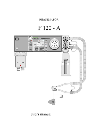
REANIMATOR
F 120 - A
Users manual
Reanimator F120-A
user manual
page 2
This manual answers your questions about the operation and care of F120 A. The manual does not contain any information about repairs and installation. If any malfunctions occur while operating the device, please contact an authorized Customer Service of F. STEPHAN GMBH or the authorized specialist dealer who supplied the device and who familiarized you with its function and operation. The manufacturer only guarantees the safety and reliability of F120 A. when it is operated according to the manual
F. Stephan GmbH - Medizintechnik Kirchstraße 19 56412 Gackenbach Technical changes without notice. Status: Version:
05. 2008 V2.4
Reanimator F120-A
user manual
page 3
Table of contents
1 2 3 4 5 6 7 8
NOTICE... 4 Preface ... 5 Range of application... 6 Specifications of the Reanimator F 120-A ... 7 Principle of performance ... 9 Description of performance. ... 11 Operating controls ... 14 Description of control-elements and indicator-elements... 17 8.1 O2-compressed air mixer ... 17 8.2 O2 - Monitor... 18 8.3 Control components annd indicators ... 19 8.4 Monitor ... 20 8.5 Patiententeil ... 21 8.6 Patientenschlauchsystem ... 23 9 Testing prior to operation ... 25 9.1 Monitoring... 25 9.2 Inspiratory pressure (Plateau), expiratory pressure (PEEP)... 25 9.3 Tightness... 25 9.4 Heater and tube heating system... 26 9.5 O2-Monitor... 26 9.6 Intake filter ... 26 10 Description of modes of ventilation ... 27 10.1 Controlled ventilation, IMV ... 27 10.2 CPAP-ventilation... 30 10.3 Manual ventilation and inflation ... 31 11 Cleaning and steralization ... 32 12 Inspection and maintenance ... 33 13 Controlelements und apparatuscomponents ... 34
Reanimator F120-A
user manual
page 4
1 NOTICE 1. Pursuant to MedGV, the apparatus must only be operated by trained personnel. Prerequisite is an exact knowledge of the operating instructions. 2. The apparatus is only intended for use as specified in the operating instructions. 3. The apparatus must be inspected periodically by trained personnel. 4. The F. STEPHAN GmbH prescribes a semi-annual inspection and maintenance by an authorised service technician. 5. A performance test has to be carried out prior to each putting into service. 6. The F. STEPHAN GmbH will not be liable for damages resulting from faulty operation due to non-observance of the operating-instructions or from use, for which the apparatus is not earmarked. 7. If possible, neither antistatic nor electrically conductive tubes should be used. 8. Prior to each putting into service a performance test has to be carried out by activating the key „AUTO TEST“. In doing so, all luminous fields must illuminate, an intermittent audible alarm must sound five times and the valve must be activated five times. 9. An apparatus for manual ventilation, independent from the Reanimator F 120-A must be close at hand. 10. The Reanimator F 120-A must only be operated with the genuine by-pack spare-parts of STEPHAN or with those parts, which are recommended by the manufacturer. 11. The conveying capacity of the built-in compressor ( optional ) changes with 12 V (DC) operation. WARNING The Reanimator must not be used with, respectively in connection with inflammable anaesthetic agents. At a room temperature higher than 32 °C, the heater of the Reanimator F 120-A must be switched off. Since the heater of the Reanimator is not regulated, respiratory gas at the tube may reach a temperature of more than 41°C. The Reanimator F 120-A can be provided with an internal accumulator. To guarantee an optimum charge of the accumulator, the apparatus must always be connected to the current supply and mains switch on the apparatus plug must be in „ON“-position during stand-by periods. With an optimum charge of the accumulator, an operating time of at least 40 minutes is secured. The time to recharge the discharged accu takes at least 12 h and is shorter when the accu charging level is higher.
Reanimator F120-A
user manual
page 5
2 Preface The STEPHAN Reanimator F 120-A is a ventilator unit for neonatal and perinatal shortterm ventilation. It operates volume-time-controlled, flow-constant and pressure-limited for controlled IMV-ventilation as well as flow-constant and pressure-limited for CPAPventilation and manual ventilation. Inspiration time is adjustable from 0,25 to 2 seconds, expiration time is adjustable from 0,25 to 30 seconds. Flow is adjustable from 0 to 30 l/min, respiratory pressure is adjustable from 15 to 60 mbar. The frequency indicator (digital) indicates, according to the setting, with controlled ventilation (IMV) the respiratory rate of 2 to 120 breaths per minute (BPM). In operating mode CPAP the display shows three bars (---). Oxygen and air are mixed in the attached twin flowmeter. Oxygen concentration is adjustable from 21 to 100% O2. An O2-monitor with adjustable minimum- and maximum value monitors the oxygen concentration with visual and audible signals. The monitor supervises visually and audibly failure of mains power and gas supply as well as disconnection and stenosis. Electronics of the respirator are controlled for one by selftesting and for the other a „Watch-dog“ has been installed, which permanently supervises the hardware of the respirator. The apparatus is provided with a heater for warming the respiratory gas. The heater consists of the heater cartridge for humidification of the respiratory gas as well as of the heated tube system to stabilise temperature and to prevent forming of condensate water. The heating system can switched on and off. The patient component P 1 consists of the heated humidifier for the respiratory gas, PEEPand inspiration-pressure valve and can be autoclaved at up 120 °C.
Option In addition to the 230 V mains supply it is possible to connect the F 120 to an external electric board network and to operate the Reanimator on 12V (DC). An internal accumulator provides the power supply, when no mains supply, respectively board network is available. Switching over to the available power supply ensues automatically and is indicated.
Reanimator F120-A
user manual
page 6
3 Range of application The Reanimator F 120 A is a ventilator for short-term and emergency ventilation of premature infants, neonates and infants. It is used in case of insufficiency of the lungs due to immaturity of lungs of neonates, of insufficiency due to a disease or failure of the respiratory mechanism.
Caution The Reanimator F 120 A ist not designed for longterm intensive care ventilation.
Option : Accu and 12 V - supply Due to the independance of any distribution voltage the Reanimator F 120-A can be operated at the incubator or in the emergency car as well as in intensive care-stations respectively birth rooms for first accomodation. The internal accu provides an operationtime of at least 40 minutes-independent from distribution voltage at max loading capacity .
Reanimator F120-A
user manual
page 7
4 Specifications of the Reanimator F 120-A Modes of operation:
-IMV (controlled ventilation) -CPAP (spontaneous respiration)
Possible settings: Inspiration time adjustable
0,25 to 2 seconds
Expiration time adjustable
0,25 to 30 seconds
O2-flow (constant) adjustable
0 to 15 l/min
Air-flow (constant) adjustable
0 to 12 l/min
Oxygen concentration adjustable
21 to 100% O2
Patient component Expiratory pressure (PEEP) adjustable
0 to 15 mbar
Inspiratory pressure (Plateau) adjustable
15 to 60 mbar
Heated humidification
12V / 10 Watt
Heated tube system Power consumption
12V / 10 Watt
Monitor Disconnection
Visual and audible alarm in case 12 mbar are not reached after expiration time + maximum inspiration time
Stenosis
Visual and audible alarm if respiratory
pressure
does not fall below 12 mbar 2,2 seconds after end of inspiration time
Failure of power supply:
Audible alarm for 120 seconds
Fault of Reanimator-electronics:
Visual and audible alarm until fault has been eliminated.
Distribution voltage:
Indication of the actual voltage ( option )
Testing program „AUTO-TEST“:
Performance test of all indicators, alarms and of the valve.
Mute of alarm:
2-min supression of audible alarm
Reanimator F120-A
user manual
page 8
Oxygen-monitor
Digital display:
21 to 99% O2 of the respiratory gas
Maximum O2-limitation adjustable:
21 to 99% O2, visual and audible warning in case of exceeding.
Minimum O2-limitation adjustable:
21 to 99% O2, visual and audible warning in case of falling below.
Automatic calibration:
Only in case of saturation with compressed air.
Indicators:
Respiratory pressure, analogous
-10 to 60 mbar
Frequency with IMV (digital)
2 to 120 respirations per minute (BPM)
Power supply:
230V/ 50 Hz mains Option :12V (DC) external, 12V (DC) internal by accu
Protective transformer:
Single phase separating transformer, power consumption 60 VA ( 75 VA with accu )
Protective class:
I, Type B
Protective category:
IP2O
Weight:
app. 10 kg ( with options app. 12 Kg )
Measurements:
L 350 x H 120 x D 210 mm
Reanimator F120-A
user manual
page 9
5 Principle of performance The Reanimator F 120-A primarily works time-controlled and pressure-limited according to the continuous-flow-principle. The fresh gas, as set on the flowmeter unit, flows during inspiration and expiration. The filling of the lungs during inspiration is accomplished by closing of the expiration valve. For manual ventilation, the expiration valve can be closed by hand.
If the set inspiratory pressure limit - inspiratory pressure plateau - is reached prior to the end of the selected inspiration time, the surplus gas is evacuated via the mechanic inspiratory pressure valve.
Expiration is effected by opening the expiration valve. Hereby the lungs evacuate due to the decrease of pressure. Expiratory gas and fresh gas together are evacuated via the expiration valve. From this results the following important consistency, common to all constant-flow-appliances: The minute volume as set on the flowmeter unit is the maximum quantity of fresh gas available to the patient for the period of one minute. Dependent on the set respiratory cycle (inspiration time + expiration time, respiratory time ratio) the patient receives only part of the set minute volume, since part of the fresh gas is lost during expiration and when the pressure plateau has been reached and consequently is no longer available to the patient. From this follows, that the set minute volume on the flowmeter unit must always be higher than the inspiratory minute volume that the patient is supposed to receive.
Dependent on the system this results, according to the set flow, in an increase of the endexpiratory pressure, indicated on the pressure gauge.
Reanimator F120-A
user manual
page 10
Due to the danger of hyperextension of the lungs of babies and infants, ventilation with pressure limitation is decisive. To administer a sufficient volume of gas under this limitation, a constant flow is offered. This may be more than the patient is able to take in. Therefore, different respiratory patterns may result.
With an increased offer of flow, the pressure limit is reached fast, here the airway resistance caused by the development of turbulences becomes specially perceptible. Flow in the trachea remains on a uniform high level only for a short period of time, since the lungs with low compliance keep filling.
With a low offer of gas flow the set pressure limit is reached later. Here the compliance of the lungs is decisive. It takes a longer time until the pressure limit is reached and the flow, which in this case develops less turbulences, remains almost constant through a long period of the inspiration time.
Reanimator F120-A
user manual
page 11
6 Description of performance. The Reanimator must be connected to the mains 230 V by means of the apparatus plug (8.2) and the attached connecting cable. The mains switch (8.3) connects the reanimator to the main power supply. With the reception coupling and the connecting tube the F 120-A must be directly connected to the oygen and Air supply ( 8.4 and 8.5 ). The fresh-gas flow level as well as the oxygen concentration is adjusted as constant flow by the two metering valves (1.1, 1.2). With the ON/OFF switch (3.1) the apparatus is switched on.
The Paediatric-Reanimator F 120-A is a time-controlled and pressure-limited constantflow ventilator, developed for first care and emergency ventilation of babies and infants.
After switching on, the Reanimator always is in IMV-mode (3.2). In accordance with the set parameter for inspiration and expiration, controlled respirations are delivered to the patient, during inspiration the expiration valve (6.1) is closed and so the lungs of the patient are filled. At switching over into expiration, this valve opens and the air can escape from the lungs. Furthermore, a positive end-expiratory pressure (PEEP) can be set by means of the expiration valve (6.1). It acts mechanically via the set force of pressure of a spring. The inspiration valve (6.2) is a purely mechanical valve and serves to limit the respiratory pressure (Limitation of inspiratory pressure). If the set pressure is exceeded, the inspiration valve opens (inspiratory plateau) and the surplus fresh gas can escape into ambient air and no longer reaches the lungs of the patient.
The switching cycle of the expiration valve can be set by means of coding switches for inspiration (3.6) and for expiration (3.8). The respiratory time ratio results automatically from the settings of inspiration and expiration. Respiratory frequency is calculated from the set parameter and displayed digitally in the three-digit display (3.7).
The keys 3.2 and 3.3 serve to change the mode of ventilation. After switching the Reanimator on, the ventilation mode IMV is automatically activated. By depressing the key for CPAP (3.3), the apparatus is switched over into the spontaneous breathing mode.
Reanimator F120-A
user manual
page 12
In doing so, the expiration valve is switched currentless. The patient can now breathe spontaneously, using the offered flow of fresh gas. Furthermore, an end-expiratory pressure (PEEP) can be adjusted by means of the expiration valve (6.1). After depressing the key IMV (3.2) the ventilation mode returns to controlled ventilation (IMV). With the key for the heater (3.4) the heater cartridge (6.5) in the humidifier for respiratory gas and the tube heating component (7.3, 7.4) are switched on and off. The fresh gas is warmed by the heater cartridge (6.5) and is conducted through the humidifying bottle (6.4), which is filled with distilled water. The heated tube system (7) maintains a constant temperature of the warmed and humidified respiratory gas and thus prevents forming of condensate water in the tube. The elements of the heater cartridge and of the tube heating system are dimensioned so that a temperature of app. 37°C results. The Reanimator is provided with a monitor for supervising the respiratory pressure (4) and with a monitor for supervising the oxygen concentration (2). The pressure monitor (4) warns in case of failure of power supply, gas supply, disconnection and stenosis. The failure-of-gas-supply-alarm, respectively the stenosis alarm (4.2) sounds, if the permanently installed pressure limit is not exceeded by the respiratory pressure after the set expiration time + maximum inspiration time (2 seconds). Stenosis alarm (4.1) activates, if respiratory pressure does not fall below the permanently installed pressure limit 2,2 seconds after end of inspiration. The oxygen monitor (2) supervises the concentration of oxygen in the respiratory gas. This monitor can be switched on and off by means of the ON/OFF-key (2.3). The O2-sensor is permanently installed in the Reanimator. An upper alarm limit (2.5) and a lower alarm limit (2.4) can be set with the help of the coding switches. The alarm limits are activated only with the O2-monitor switched on. If they are exceeded or fallen below, an audible and visual (2.6) is released. The O2 monitor has to be calibrated anew from time to time for 21% oxygen, using the Cal.-key (2.1). To do so, it is necessary to cut off the oxygen supply by rotating the proportioning valve (1.1) to its right stop. During calibration, the O2-sensor must only be saturated with compressed air !! The audible alarm of all monitor functions can be muted for 2 minutes by means of the „2min-key“ (4.3). Prior to every putting into service, a performance test has to be carried out by depressing the key „AUTO TEST“. Hereby all luminous fields must illuminate, intermittent audible alarms must sound five times and the valve must activate five times.
Reanimator F120-A
user manual
page 13
Option The Reanimator F 120-A can be equipped with several additional components. compressor for independent compressed air supply, internal accu with a capacity of app. 40 min. connection for external 12V-supply automatically switch over to the left distribution voltage indication an d control of the actual distribution voltage automatically charging control of the internal accu. The air pressure supply can be provided by an additional compressor ( 8.13 ).The compressed air outlet (8.14 ) is directly connected to the DIN-coupling of the reanimator. It can be switched ON/OFF with a seperate switch at the frontplate of the Reanimator F 120A. If the F 120-A is equipped with an internal accu , the mains switch (8.3) should always be switched on, so that the internal accu can be charged during endurance. By means of the 12V-socket ( 8.6 ) an external 12V-power supply can be connected. The internal distribution voltage detection indicates and controls the actual power supply. The loading capacity of the internal accu as well as the 12V-on-board-supply is supervised. When the minimum supply is falling short, every 30 seconds a warning tone is released. It can not be suppressed and the equivalent potential indicator starts flashing. As of this time, 20 minutes operation time remains. If the power supply falls below a critical level, the apparatus is automatically shut off.
Reanimator F120-A
user manual
7 Operating controls 1. O2-compressed-air mixer 1.1 Proportioning valve for flow 1.2 Proportioning valve for O2-concentration 1.3 Alarm unit gas supply 1.4 Indicator for failure of supply 1.5 Compressed-air connection 1.6 Oxygen connection 2. O2- Monitor 2.1 Key for calibration to 21 % O2 2.2 Two-digit display of O2-concentration 2.3 ON/OFF-switch of O2-monitor 2.4 Coding switch for minimum O2-concentration 2.5 Coding switch for maximum O2-concentration 2.6 Visual alarm O2-alarm 3. Control component 3.1 ON/OFF-switch of Reanimator 3.2 Key „Ventilation mode IMV“ 3.3 Key „Ventilation mode CPAP“ 3.4 Key „Heater ON/OFF“ 3.5 Key „Reanimator AUTO TEST“ 3.6 Coding switch for setting of inspiration time (sec.) 3.7 Indication of respiratory frequency (only with IMV) 3.8 Coding switch for setting of expiration time (sec.) 4. Monitor 4.1 Visual alarm for stenosis 4.2 Visual alarm for failure of gas supply or disconnection 4.3 Key for muting the audible alarm (2 minutes) Option : 4.4 Indication of internal power supply 12 V (DC) by accumulator 4.5 Indication of external power supply 12V (DC) from board network 4.6 Indication of power supply 230V (AC), on the line
page 14
Reanimator F120-A
user manual
5. Respiratory pressure gauge 5.1 Zero point adjustment 6. Patient component P1 6.1 Expiration valve (electro-magnetical), PEEP valve (mechanical) 6.1.1 Push button for manual ventilation 6.2 Inspiration valve (inspiratory pressure limitation, Plateau) 6.3 Fastening screw for Patient component P1 6.4 Humidifier bottle 6.5 Heater cartridge 6.6 Distilled water 7. Patient tube system 7.1 Heated tube system, expiration branch 7.2 Heated tube system, inspiration branch 7.3 Electrical connection of heated tube system, expiration branch 7.4 Electrical connection of heated tube system, inspiration branch 7.5 Y-piece 7.6 Tube-connector, size 1 to 4 7.7 Respiration masks, size 0 to 3 8. Housing and supplies 8.1 cable for mains supply 8.2 apparatus plug for power supply 230 V (AC) 8.3 Power switch for mains supply and accu charging 8.4 DIN-coupling for O2-gas-supply 8.5 DIN-coupling for AIR-gas-supply 8.6 OPTION : Apparatus plug for power 12V (DC) of on-board-supply 8.7 Audible alarm 8.8 Potential earth connection 8.9 Fuse holder for 230V (AC) 0,5 AT 8.10 Fuse holder for 230V (AC) 0,5 AT 8.11 Fuse for heating 1x3 15 AT 8.12 OPTION : Fuse for the internal accu 12V (DC) 1x4 AT 8.13 OPTION : compressor
page 15
Reanimator F120-A 9. Suction 9.1 ON/OFF-switch 9.2 / 3 connections of suction unit
user manual
page 16
Reanimator F120-A
user manual
page 17
8 Description of control-elements and indicator-elements 8.1 O2-compressed air mixer
1 O2-compressed air mixer for mixing the respiratory gases and setting of flow 1.1
Proportioning valve for setting of oxygen concentration in the respiratory gas
1.2
Proportioning valve for setting of the fresh gas flow
1.3
Sight-mark for visual indication of failure-of-gas-supply.
1.4 Standard screw connection for oxygen supply. Connection is made in accordance with the coding to the central gas supply or directly onto the STAXEL. 1.5
Standard screw connection for compressed-air-supply connection is made in accordance with the coding or directly onto the STAXEL.
Attention: The proportioning valves must not be closed too hard. Overtightening will damage the spindle, leading to leakages.
Reanimator F120-A
user manual
page 18
8.2 O2 - Monitor
O2Monitor
%
2 2.2
1 0
O2 max -
2.1
ambient air. The sensor is permanently
installed in the Reanimator. During calibration the sensor must only be saturated with compressed air.
9
I.e. the proportioning valve for oxygen on the
+
flowmeter (1.1) must be rotated to its right stop, so
O2 min -
2 +
Calibration key for adjusting the sensor to 21% O2 with
2.3 2.5
9
O2-monitor for control of oxygen concentration in the fresh gas.
2.1
CAL 21%
2
1
that the supply with oxygen is cut off.
2.4 2.2
Digital display of O2-concentration. Indication is displayed independent of the O2-monitor being switched on or off.
2.3
ON/OFF-switch of O2-monitor.
2.4
Coding switch for setting the minimum oxygen concentration. In case of falling below this limit, a visual and audible alarm is released.
2.5
Coding switch for setting the maximum oxygen concentration. In case of exceeding this limit a visual and audible alarm is released.
A visual and audible alarm ensues, if the set limit values are exceeded or fallen below. By means of the key „2 min“ (4.3) the audible alarm can be muted for 2 minutes. The visual alarm (2.6) ceases only after the fault has been eliminated.
Reanimator F120-A
user manual
page 19
8.3 Control components annd indicators
3
Timer for setting the respiration times (inspiration and expiration) as well as indication of the respiratory frequency. Setting of the respiration times and indication of the respiratory frequency is activated only in connection with the ventilation mode IMV (3.2). With venti-lation under CPAP (3.3) the display shows three bars (---).
3.1
ON/OFF-switch of Reanimator F 120 A
3.2
Key for changing to ventilation mode of controlled ventilation (IMV)
3.3
Key for changing to ventilation mode of spontaneous ventilation (CPAP)
3.4
Key for switching the heater on and off (humidifier of the respiratory gas, tube heating system)
3.5
Key for starting AUTO-TEST of Reanimator. Hereby the performance of all inputand output elements is tested.
3.6
Coding switch for setting the inspiration time.
3.7
Indication of respiratory frequency with IMV. The frequency is calculated from the settings of inspiration time and expiration time.
3.8
Coding switch for setting the expiration time.
9.1
ON / OFF-switch of the suction. It is driven by compressed air ( in case of internal compressor the driving gas is oxygen ).
OPTION: 8.15 ON / OFF-switch for additional compressor
Reanimator F120-A
user manual
page 20
8.4 Monitor
MONITOR 2min
. 4
4
4.3
4.1
Activated only with ventilation mode IMV.
pressure limit of 12 mbar is not fallen below 2,2
4.1
seconds after the set end of inspiration time (stenosis)..
2.6
4.2
O2-ALARM AKKU
Visual alarm ensues, if the permanently installed pressure limit of 12 mbar is not exceeded after
4.4
the set expiration time + maximum inspiration time (2
NETZ 12V NETZ 230V
Visual alarm ensues, if the permanently installed
4.2
DISCONNECT STENOSE
Monitor for supervision of the respiratory pressure.
4.5 4.6
sec), (Failure of gas supply, disconnection). 2.6
Visual alarm in case of violation of the set limit values
for oxygen concentration.Alarm activates only with the oxygen monitor switched on.
4.3
Key for muting the audible alarm for 2 minutes. By pressing, all audible alarms are muted for 2 minutes, whereby the visual alarms remain active. If the alarm condition still persists after 2 minutes, the audible alarm will be released again. Audible and visual alarm cease only, when the cause for the alarm has been eliminated.
4.4
OPTION : Indication of supply voltage for 12V (DC), internal accumulator.
4.5
OPTION : Indication of supply voltage for 12V (DC), external.
4.6
OPTION : Indication of supply voltage for 230V/50 Hz (AC)