User Manual
77 Pages
Preview
Page 1
1 Pictographs 1 Pictogramas I Syrnboles 1 Bildreichen /
I
1
operating manual
iAtencibn! Observe la documentaci6n adjunta
1
Attention, lire la documentation jointe!
Simbolo para un aparato del tip0 BF
1
Symbole pour un appareil de type BF
I
Symbol for type BF equipment
I
1 tion Degrees of protec- I Grado de protec- 1 Degres de protec- ( 1 provided by c~onproporcionado tion procures par Gehauseschutz-
I
Se~icio
Service
Service
REF
Order number
N h e r o de pedido
R6firence produit
Bestellnummer
@
Single useonly
Lot no.
SN
/
1
Esterilizadocon ETO
1
Denominacibn departida o lote
Serial number
-
Pieces, quantity
Latex free
Numberof
1
' '
Usage unique
klasse (IP-Code)
1
w :e$ d :u:ng
Sterilises iI'ETO
1
NumerOde lot
I
I
1
Sterilisiert m i t ETO
1
Chargenbezeichnung
Nlimero de serie
NumCro de serie
Seriennummer
Utilizable hasta
~
Vetwendbar ~ lbis
1
1
Expiration day
I 1@ 1
No reutilizable
lesenveloppes
/I
Service
STERILE EO sterile vnth ETO
1
I
/ (Code IP)
' 1 I I
II
5ymbolf"rden Potentialausgleich
o ;r losenvolventes [ ~ b d i g oIP)
--
enclosures (IP-Code)
$$pra la Fiche equipotencial equipotentielle
1
Symbol f i r e i n Gerat des Typs BF
I
1 1P 4- -1 1I
I
1
1
equalization
1
1
Achtung Begleitpapiere beachten
I 1
Pieza, cantidad
sin latex
I I
~
Pieces, quantite
sans latex
I
1
Anzahl, Menge
atexfrei
Numero de Autoklavierungen
~
I 1
~
~
~
n
1
1 tf 1
I
)
P
I
/ -----.
a
Pictographs
get wet
Top-Bottom
/
1 1
Proteger contra la humedad
Arriba-abajo
1 /
I
Proteger de l'humiditl
Haut - bas
1 1
Bildzeichhen Vor Nasse schiitzen
Oben - Unten
Fragile
Frigil
Fragile
I.
Heater
Calefacci6n
Chauffage
Heizung
IncreaselDecrease
iE$iE:e
Croissan t l decroissant
Zunehmendl abnehmend
Connectorsignal input
Entrada para seiiales
Entreede signaux
Eingangfur Signale
signal output Connector-
I
Salida para seiiales
I
Sortie de signaux
Zerbrechlich
1
p,usgawfur "gna-
Direct current
Corriente continua
Courant continu
Cleichstrom
Gas output
Salida degas
Sortie de gaz
Gasausgang
I
I I I
1 I
2
1
1
Manufacturer
Stryker European Representative
1
Fabricante
Representante europeo de Stryker
(
Fabricant
Representant Stryker Europe
I
1
Hersteller
~
~ in
~
~
~
n
g
... ... ...
Important User Notes 1 Safety Instructions 3 2.1 Dangers and Risks ...4 Purpose of the Device 7 3.1 Device-inherent Dangers ...8 Manufacturer's Notice: Device Versions ... 12 3.2 Initial Use of the Device 13 4.1 Gas Connection ...1 4 Operating the Device 15 5.1 Front of the Device ...15 5.2 Display ...15 5.3 Rear of the Device ...16 5.4 Device Setup ... 16 5.4.1 High Flow Application ...17 5.4.2 Low Flow Application (optional) ...17 5.5 Gas Supply Display ...18 5.6 Presetting Nominal FlowINominal Pressure with High Flow Application ... 18 5.6.1 Presetting Nominal Pressure with High Flow Application ... 18 5.6.2 Preselecting Nominal Flow with High Flow Application ... 19 5.7 PreselectingNominal Flow/Nominal Pressure with Low Flow Application ... 2 1 5.7.1 PreselectingNominal Pressure with Low Flow Application ... 22 5.7.2 Preselecting Nominal Flow with Low Flow Application ...23 5.8 StartIStop Key ... 25 5.9 Actual Pressure Display ... 26 5.10 Gas Consumption Display ... 26 26 5.11 lnsufflation Tube Connection ... 26 5.12 Gas Heating ... 5.13 Switching Device Off ...28 Safety Functions 29 User Menu 33 43 Options 8.1 Video Messaging (Superposition) ...43 Function Test 45 9.1 Testing the Device ... 45 9.2 Testingthe Veress Cannula ... 46 9.3 Fill Tube System with CO2 ...47 Use of the Device During Surgery 49 10.1 lnsufflating with Veress Cannula ... 49 10.2 lnsufflating with the Trocar ...49 Care and Maintenance 51 11.1 Cleaning the Device ... 51 11.2 Cleaning of the Reusable Tubing Set ...5 1 11.3 Disinfecting the Reusable Tube Set ... 51 52 11.4 Sterilization of Reusable Tube Set ... 11.5 Annual Inspection ...52 11.6 Maintenance Carried out by Authorized Service Technician ...52 11.7 Replacingthe Fuse ...53 Annual inspection 55 12.1 Safety Test ...55 12.2 Basic Function Test (in High Flow Mode) ...55 12.3 Test of the Pressure Sensors ... 56 12.4 Pressure Monitoring Test ...57 12.5 Venting Valve Test ...57 12.6 Max. Device Pressure Test ...58 12.7 Gas Flow Rate Test ...58 Technical Data 59
... ...
... ... ... ...
...
...
...
...
Contents
14
15
16 17
*W
...
Electromagnetic Compatibility 61 14.1 Impact of Mobile and Portable RF Communication Devices ... 6 1 61 14.2 Electrical Connections ... 61 14.3 Accessories ... 14.4 Guidelines and Manufacturer's Statement - Electromagnetic Emissions ... 62 14.5 Guidelines and Manufacturer's Statement - Electromagnetic Interference Immunity ... 62 14.6 Guidelines and Manufacturer's Statement - Electromagnetic Interference Immunity 40L Core lnsufflator ... 63 14.7 Recommended Safety Distances Between Portable and Mobile RF Telecommunications Devices and the 40L Core lnsufflator ... 64 Accessories 65 15.1 Accessories for 40L Core lnsufflator with Integrated Low Flow, Mode US ... 65 15.2 Accessories for 40L Core Insufflator with Integrated Low Flow, Mode EU ... 65 15.3 Remote Control (only for EU Version) ...66 Error and Warning Messages 69 Appendix 71 17.1 Test Record ...7 1 73 17.2 Return Form ... ...
...
... ...
s t *
Important User Notes Important User Notes
1
Read the manual carefully and become familiar with the operation and function of the device and the accessories before using either for surgical procedures. Noncompliance with the manual may lead
Readingthis Manual
t o life-threatening injuries of the patient, t o severe injuries of the surgical team, nursing staff or service personnel, or t o damage or malfunction of device andlor accessories. The manufacturer reserves the right to modify the appearance, graphics, and technical data of the product through continued development of the product.
Subject toTechnical Changes
Paragraphs with the words DANCER, WARNING, and NOTE carry special meanings and should be read attentively. -
-
-
- -
-
-
- -
- -
The safety and/or health of the patient, user, or a third party is at risk. Comply with this warning to avoid injury to the patient, user, or third party.
These paragraphs contain information concerning the intended and proper use of the device or accessory.
A
DANGER
a
WARNING Here you will read informationabout the maintenance of the device or accessories.
El NOTE
Important User Notes
stw-
iI Left Blank on Purpose
1'
Safety Instructions
2
Safety Instructions
U.S. federal law restricts use of this device by or on the order of a physician.
U.S. Federal Law (Only for U.S. Market)
The manufacturer does not assume any liability for direct or consequential damage if:
No Liability
the device orthe accessories are improperly used, prepared, or maintained; the instructions and rules in the manual are not adhered to; non-authorized persons perform repairs, adjustments, or alterations on the device or accessories; non-authorizedpersons open the device; the prescribed inspection and maintenance schedule is not adhered to. 1
1
4
1
I
Receiving technical documentation from the manufacturer does not authorize individuals t o perform repairs, adjustments, or alterations on the device or accessories/peripherals. Only an authorized service technician may perform repairs, adjustments, or alterations on the device or accessories and use the service menu. Authorized service technicians are only trained and certified by the manufacturer.
Authorized Service Technician
To guarantee safe operation, it i s absolutely necessary to carry out proper care and maintenance of the device and accessories. For the protection of the patient and the operating team, check that the device is complete and functional before each use.
Care and Maintenance
New products as well as repaired products must be prepared and tested according t o the manual instructions priorto use. For the protection of the service personnel and to maintain safety during transportation, all devices and accessory parts that are sent in to be repaired must be prepared for shipment as described in the manual.
Contamination
If this is not possible,
the product must be clearly marked with a contamination warning and double-sealed in safety foil. The manufacturer has the right t o refuse carrying out repairs if the product is contaminated. This symbol indicates that the waste of electrical and electronicequipment must not be disposed as unsorted municipal waste and must be collected separately. Please contact the manufacturer or other authorized disposal company to decommissionyour equipment.
Waste Management
S t -
Safety Instructions
2.1
A A A
DANGER
Dangers and Risks
Condensation/Water Penetration Protect device from moisture. Do not use if moistureor liquid has penetratedthe device.
Original Accessories For your own safety and that of your patient, use only original accessories.
DANGER
DANGER
A
DANGER
A A A A
DANGER
DANGER
DANGER
DANGER
Factory Settings Check all user menu settings and values (cf. chapter 7 User Menu, page 33). Such internal standard settings are not necessarily prescribedfor the doctor. The doctor i s responsible for all settings that pertain to the operation performed by him/her.
Technique and Procedures Only the physician can evaluate the clinical factors involved with each patient and determine if the use of this device is indicated. The physician must determine the specific technique and procedurethat will accomplish the desired clinical effect.
Available Mains Voltage Check to make sure that the available mains voltage matches the data listed on the label attached to the back of the device. Incorrect voltage can cause errors and malfunctions and destroy the equipment.
Not Explosion-Proof Electrical components are not explosion-proof. Do not use in an area where flammable gases are present.
Risk of Electrical Shock To prevent electrical shock, do not open this device. Never open this device yourself. Refer servicingto qualified service personnel.
ReplacingFuse Replace the fuse only with a fuse of the same type and rating.
St-
Professional Qualification This manual does not include descriptions or instructions for surgical proceduresltechniques. It i s also not intendedt o introduceto or train physiciansin the use of surgical techniques. Medical accessories and devices may be used only by physicians and medical assistants under the direction of a physicianwith the appropriate technicallmedical qualification. Only specially trained and qualified personnel may use this device on children.
Safety Instructions
A
DANGER
Function Test The function test must be performed prior to each operation. I
DANGER Sterile Substances and Accessories Always work exclusively with sterile substances and mediums, sterile gas, and sterile accessories.
Cleaning the Device Do not sterilize the device.
A A A
DANGER
DANGER Replacement Device and Accessories In case the device or any of the accessories fail during an operation, a replacement device and replacementaccessoriesshould be kept within easy reach to be able to finish the operation using the replacement device or replacement accessory.
Device-inherent Dangers Read the warnings specific to this device in chapter 3 Purpose of the Device, page 7.
DANGER
A A A
DANCER Device Defect If a device defect is suspected or confirmed, stop using the device until it has been checked by authorized service personnel.
Endoscope The device may only be connected to endoscopes designed for use with the device for the intended medical procedure. The endoscopes must comply with the most recent versions of IEC 60601-2-18 and I S 0 8600.
DANGER
DANGER
Safety Instructions
Left Blank on Purpose
6
I
Purpose of the Device
3
Purpose of the Device
The device serves to insufflate CO2 into the abdomen during a diagnostic or therapeutic laparoscopy. Please consult the instructional manual of your laparoscope for additional information and special application indications.
Intended Use
The insufflator has two operating options. The High Flow application limits the pressure to max. 30 mm Hg (mm mercury column) and the gas flow to max. 40 Ilmin.
High FlowApplication
The device measures the pressure within the abdomen in short intervals and continuously compares the nominal with the actual abdominal pressure. The function of the device is to maintain the nominal or set point pressure. Any overpressure within the abdomen is lowered to the preset nominal pressure by the automaticventing system. The Low Flow application limits the pressure to max. 20 mm Hg (mm mercury column) and the gas flowto max. 20 Ilmin.
Low Flow Application
The Low Flow application is specially designed for use on newborns, infants, and children. When used on children, it is recommended to control and adjust the device and the nominal flow based on the following factors:
Age Group
Weight
Flow Range
Children youngerthan 1 year
approx. 1-9kg
0.1 -0.5Ilmin
Children between 1 to 3 years
approx. 10-15kg
0.5 -1.0Ilmin
Children between 3 to 4years
approx. 16-19kg
1.0 -2.0Ilmin
Children between 4to 14years
2 20 kg
> 2.0 l/min
The nominal pressure cannot be reached if the nominalflow is set too low. Check for possible leaks.
1
Due t o the special operating method used during the Low Flow application (optional), the speed of equalizing the leak is slower than when using the High Flow application (lower effective flow in Low Flow application).
I I
i
The device may not be used to fill an abdomen with CO2 if a laparoscopy i s contraindicated. Please consult the instructional manual of your laparoscope for absolute and relative contraindications.
i
I I
I
The device is not suitable for hysteroscopic insufflations, i.e.. it may not be used to distend the uterus. The gas flow may not exceed 14 Ilmin when performinga laparoscopy on infants or patients weighing less than 25 kg.
Contraindications
Purpose of the Device
3.1
DANGER
Gas Flow Limit The gas flow may not exceed 14 I/min when performinga laparoscopy on infants or patients weighing less than 25 kilos. -
A A
Device-inherentDangers
-
-
-
-
-
-
-
-
-
-
Pneumolabium/Pneumoscrotum Children are at risk of a pneumolabium or pneumoscrotum.
DANGER
DANGER
A
DANGER
A A
DANGER
DANGER
A
DANGER
Increased Airway Pressure/Compression of the Vena Cava When using the Low Flow application on children, an increased risk of high airway pressure and/or compression of the vena cava (low input syndrome) exists.
Positioningthe Patient Always position the patient lower than the device to prevent body fluids from leaking into the device. Intra-abdominal pressure can be increased and fluid can penetratethe insufflation tube if the patient is repositionedduring surgery. If this occurs, immediately disconnect the insufflation tube at the trocar. When the patient i s placed on an angle, shifting of internal tissue may block the insufflation channel. Always insufflatethrough the elevated side of the patient.
Idiosyncratic Reactions Patients with sickle cell anemia or pulmonary insufficiency may have a higher risk of metabolic imbalance related to excessive C 0 2 absorption (idiosyncratic reaction). -
-
CO2 Absorption CO2 is absorbed during insufflation (intravasation). lntravasation causes the body to absorb part of the CO2 gas used for insufflation. CO2 concentrationsin the blood or respiratory system that are too high can lead todeath of the patient in extreme cases. To lower this risk, always carefully and closely monitor the patient's vital signs during the entire insufflation process and make sure patient is breathingwell. Sufficient respirationcan help avoid or limit problems with CO2. High pressure or high gas flow promote CO2 absorption.
Metabolic and Cardiac Reactions A pressureof more than 20 mm Hg can result in metabolic acidosis. This can lead to cardiac irregularities and the following symptoms : Reduced respiration with restricted diaphram function Reduction of venous reflux Reduced cardiac output Metabolic acidosis
stryker'
Hypothermia/Monitoring Body Temperature The gas flow can lead to a lowering of the patient's body temperature during insufflation. This in turn can cause heart and cardiovascular problems. Always monitor the patient's body temperature during the entire insufflation. Make especially sure that the following, hypothermia promoting, operation conditions are avoided as best as possible: *High gas flow due to large leaks Long surgeries U s e of cold (not preheated) irrigation and infusion solutions. The risk for hypothermia can be significantly reduced with the use of gas pre-warmedto body temperature.
Dehydration lnsufflation can lead to dehydration of the tissue. This can result in organ tissue damage and cardiovascular reactions of the patient. Long surgeries and large leaks increase the risk of dehydration (especially at the insertion points of the trocars or when changing instruments).
Embolism Improper placement of the insufflation instrument could cause insufflation of gas into a vessel, resulting in air or C 0 2 embolisms. To reduce the risk of air or COZ embolism, perform initial insufflation at a low flow rate and ensure that the insufflation instrument i s correctly positioned. Check the position of the insufflation instrument immediately if the actual pressure rapidly reaches the nominal pressurevalue. CO2 embolisms can also be caused by a high intra-abdominal pressure. Avoid high pressure settings and close damaged blood vessels at once.
Additional lnsufflation Sources The use of additional insufflation sources increases the intra-abdominal pressure. Continuously monitor intra-abdominal pressure over the course of the entire insufflation if additional sources are used.
Disconnecting the lnsufflation Tube Always disconnect the insufflation tube after ending surgery and before switching off the device to prevent backflow of bodily fluids. Fluid may penetrate the insufflation tube whenever you change the gas cylinder and/or when you stop the gas flow during the operation. If this happens, you must immediatelydisconnect the insufflation tube from the trocar or from the device.
Backflow Body secretion or contaminated gas can result in a backflow into the device, if *a filter is not used, *the actual pressure is higher than the nominal pressure or *the automatic venting valve is activated.
Purpose of the Device
A DANGER
A
DANGER
A
DANGER
A A
DANGER
DANGER
A
DANGER
SImkeP
Purpose of the Device
A
DANGER
A A A
DANGER
DANCER
DANGER
A A
DANCER
DANGER
Gas Flow A high gas flow can be due to large leaks within the surgical system or instrument. This can result in an false actual pressure reading, which in turn may endanger the patient. In case of a disrupted gas flow you should therefore inspect device, tube, and instruments immediately. It i s recommended to perform laparoscopies with the lowest gas flow possible.
Keep Filled C02 Bottle on Hand Always keep a filled CO2 bottle on hand ready for replacement. This avoids having to interrupt surgery due to a lack of insufflation gas (cf. chapter 16 Error and Warning Messages, page 69).
Contamination Do not use device andlor accessories if signs of a contamination are detected. Make sure the devicelaccessoriescan no longer be operated until a qualified service technician conducts the appropriate tests and repairs.
Fatigue Symptoms When there is a high level of CO2 consumption, you should make sure to supply the operating area with enough fresh air, since an increasing C02 level in the air can cause the medical personnel to suffer fatigue symptoms, an inability to concentrate, unconsciousness, or even death.
Automatic Venting System The automatic venting system has a limited venting rate. Whenever you use additional insufflationsources, you should constantly monitor the intra-abdominal pressure.
Filter Use a newlsterile filter for each patient. You must work with a 0.2 pm two-way (retention rate 99.99 %) hydrophobic filter between patient and device. This should prevent bodily fluids from entering the device and also prevents impuritiesfrom possibly entering into the patient's body. Reducedflow capacity should be considered when using a hydrophobic filter. -
A A
DANGER
DANGER
-
-
ContaminatedFilter Exchange a contaminated filter immediately during surgery to ensure an unhindered gas flow.
Connecting the Tube The tube outlet may only be connected to instruments which are intended for intra-abdominal CO2-insufflation.
Purpose of the Device
Electronic Device Control The valve located at the trocar sleeve may not be closed intraoperatively. The electronic control unit of the device adjusts the intra-abdominal pressure as desired.
I
Medically Pure C02 Make sure t o use only medically pure CO2. Other gases (i. e., helium, NzO, argon), mixtures of gases, high pressure compressed gases, gases with entrapped liquids, or polluted gases may not be used with this device.
Service Connection Connected devices have t o comply with the standard EN 60950. Devices may not be connected t o the service connection during the surgical procedure.
Electromagnetic Interference (cf. chapter 14 Electromagnetic Compatibility, Page 61) Electromagneticinterferencewith other devices or instrumentswas practicallyeliminated when developingthis devices and none was detected during testing. However, if you still detect or suspect such interference, please follow these suggestions: *move this device to a different location or move the other device, *increase distances between all used devices, *consult an electromedicineexpert. -
-
A A A A
DANGER
DANGER
DANGER
DANGER
-
Peripheral Devices Additional equipment connected to the interfaces of the device have to meet the following specifications: EN 60601-2-18 for endoscopic devices and EN 60601-1for electrical medical devices. All configurations have t o comply with EN 60601-1-1specifications. A person connecting additional devices to the signal IN or OUT sockets is considered to be a system configurator and as such responsible for adherencewith the EN 60601-1-1 standard.
A
DANGER
.
-
Purpose of the Device
3.2
Manufacturer's Notice: Device Versions
0620-040-511
SIDNE
EN, NL, FR, DE
0620-040-512
SIDNE
EN, NO, SV, DA, FI
0620-040-513
SIDNE
EN, ES, IT, PT, EL
Initial Use of the Device
Strykw 4
Initial Use of the Device
Always check all parts and accessories of the device immediately after receiving the shipment. Inspect for external damage as well. The manufacturer considers only replacement claims that have been immediately submitted or reported t o a sales representative or an authorized service company.
Input Control
If it becomes necessary to return the device, use of the original packaging is required. The manufacturer does not take responsibility for damage that has occurred during transportation if the damage was caused by inadequate transport packaging.
Returningthe Device
Please fill out the return form enclosed at the end of the manual. Enclose the manual with the device. Please make sure that all required information has been supplied: Name of owner Address of owner Device type Serial number (see identification plate) Description of defect Place the device on a level surface i n a dry environment. The ambient temperature has t o range from 10"C t o 40 "C; the relative humidity has t o be between 30% and 75%.
Setup
A
Electricalcomponentsare not explosion-proof. Do not use in an area where flammable gases are present.
DANCER Power Supply
Check to make sure that the available mains voltage matches the data listed on the label attached to the back of the device. Incorrect voltage can cause errors and malfunctions and destroy the equipment.
a
WARNING
Make sure the connection data and technical specifications of the power supply comply with DIN VDE or national requirements. The power cord may be plugged only into a properly installed safety wall plug (see DIN VDE 0107). Read the device label (device data plate) located in rear of device t o determine the operating voltage of the device. The power supply has t o be grounded. Use the original power cable to plug into the wall socket on one side and the rear device jack on the other.
Protective Contact
Use only an approved detachable power supply cable, type SJT, minimum 18 AWG, 3 conductors, one end configured for NEMA 5-15, other end for IEC 320/CEE22.
Onlyfor US Operators
Grounding will only be reliable if the equipment is connected t o a corresponding hospital grade socket. Integrate the device into the potential equalization system according t o local safety rules and regulations.
Equipotential Bonding
-
Initial Use of the Device
4.1
A
DANGER
Gas Connection
Always use medical grade CO2. Never use any other type of gas.
Use a high-pressure tube to connect a C02 gas bottle t o the rear gas inlet connedion or conned t o centralized C02 gas supply.
Gas Bottle
a
WARNING
8
Always use a high-pressuretube t o connect gas bottle and device.
The gas bottle has t o be in a vertical position. 1
Gas bottles with riser pipe can release dirt and oily fluids into the device. Do not use a gas bottle with riser pipe.
I
WARNING Gas Connection
II
The gas bottle pressure may not exceed 80 bar.
I
1. Connect the high pressure tube t o the gas connedion.
2. Fix the high pressure t u be with the nut. 3. Tighten the nut.
Operating the Device 5
Operating the Device
5.1
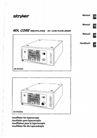
Front of the Device Fig. 5.1.1 Front of the Device Startlstop key
a a Display a Gas heater connection @
lnsufflation tube connection
a lncreasing nominal gas flow Reducing nominal gas flow
a Gas consumption reset key @
Menu key lncreasing nominal pressure
5.2
(lo)
Reducing nominal pressure
(11)
IRsensor
(12)
ONIOFF key
Fig. 5.2.1
Display
a
Actual flow
@
Nominal gas flow
Display
a Status display1Error & warning messages a Actual pressure a Gas consumption
I
lnsufflation stopped - 15mrnHg1
0.01
I
I
I- I pin
I
Gassupply
a Nominal pressure
Operating the Device
Fig. 5.3.1
StPYkeF 5.3
RearoftheDevice
5.4
Device Setup
Rear of the Device
a Type plate
@
Device data plate SIDNE Interface (optional) Data inputloutput
a Connection for equipotential bonding Sockets for VIDEO RGBICSCC OUT Signal (optional)
a Socket for VIDEO S-VHS OUT Signal (optional) Sockets for the VIDEO RGBICSCC IN Signal (optional)
@
Socket for the VIDEO S-VHS IN Signal (optional)
(10)
Device plug
(11)
Fuse holder
(12)
Gas connection 1. Connect the gas supply t o the gas connection port. 2. Open the gas supply line.
3. Press the ONIOFF key. The device switches on.
Device check I
The device now conducts a self-test. Device ok followed by Select values appears in the display.
a
WARNING
The corresponding display is depicted after switching the device on again depending whether the device was last operated i n the High Flow or Low Flow mode. Use the user menu option "Application" (cf. 7 User Menu, page 33) to switch between Low Flow or High Flow application.