Instruction Manual
103 Pages
Preview
Page 1
DA TA CO NT RO L
TIM ER
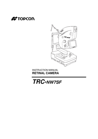
INSTRUCTION MANUAL
RETINAL CAMERA
TRC-NW7SF
INTRODUCTION Thank you for purchasing the TOPCON TRC-NW7SF Retinal Camera.
This instrument is used to observe and photograph the posterior segment on the eye. This instrument has the following features: • Mydriatic/non-mydriatic modes • Easy filter setting by using the Liquid Crystal (LC) control panel. • High-quality digital imaging • Direct LC Monitor observation without viewfinder • Adjustable position monitor • All-in-one system • Interfaces easily with personal computer for enhanced features
This manual outlines the TRC-NW7SF Retinal Camera, including operating procedures, troubleshooting, maintenance and cleaning. Before using the instrument, carefully read the "DISPLAY FOR SAFE USE" and the "SAFETY CAUTIONS" to familiarize yourself with the features of the TRC-NW7SF Retinal Camera and to ensure that you operate it in an efficient and safe manner. Always keep this Instruction Manual at hand.
[Warning] Be careful not to bump the patient’s eyes or nose with the instrument during operation. [The patient may be injured.]
1
CAUTIONS FOR USE Basic caution When taking a picture, make sure that the patient keeps his/her hands away from the movable parts to avoid possible injury. Disposal When disposing of TRC-NW7SF parts, follow the local regulations for disposal and recycling.
ENVIRONMENTAL CONDITIONS FOR USE Temperature: 10°C ~ 40°C Humidity: 30% ~ 75% (without dew condensation) Air pressure: 700hPa ~ 1060hPa
STORAGE, USAGE PERIOD AND OTHERS 1. Environmental conditions Temperature: 10°C ~ 40°C Humidity: 30% ~ 85% (without dew condensation) Air pressure: 700hPa ~ 1060hPa 2. When storing the instrument, ensure that the following conditions are met: (1) The instrument must not be splashed with water. (2) Store the instrument away from environments where air pressure, temperature, humidity, ventilation, sunlight, dust, salty/sulfurous air, etc. could cause damege. (3) Do not store or transport the instrument on a slanted or uneven surface or in an area where it is subject to vibrations or instability. (4) Do not store the instrument where chemicals are stored or gas is generated. 3. Normal life span of the instrument: 8 years from delivery providing regular maintenance is performed [TOPCON data]
ENVIRONMENTAL CONDITIONS FOR PACKAGING IN TRANSPORTATION Temperature: -20°C ~ 50°C Humidity: 10% ~ 95%
CHECKPOINTS FOR MAINTENANCE 1. Periodically inspect the instrument and its parts. 2. Before using the instrument again after a long period of inactivity, make sure that it operates safely and normally. 3. Be careful not to stain the objective lens with fingerprints, dirt, etc., as this will affect the quality of pictures that the instrument takes. 4. When the instrument is not in use, cap the objective lens and cover the instruments with the dust cover. 5. If the objective lens is stained, clean it according to "CLEANING THE OBJECTIVE LENS" on page 98 of this manual.
2
DISPLAY FOR SAFE USE To encourage safe and proper use and to prevent injuries to the operator and others or potential damage to property, important messages are put on the instrument body and inserted in the instruction manual. We suggest that everyone understand the meaning of the following displays, icons and text before reading the "SAFETY CAUTIONS" and observe all listed instructions.
DISPLAYS Display
Meaning
WARNING
Incorrect handling by ignoring this display may lead to a risk of death or serious injury.
CAUTION
Incorrect handling by ignoring this display may lead to personal injury or physical damage.
• Injury refers to cuts, bruises, burns, electric shock, etc. which do not require hospitalization or extended medical treatment. • Physical damage refers to extensive damage to the building, nearby equipment and/ or surrounding furniture.
ICONS Icon
Meaning Prohibition. Specific content is expressed with words or a picture near the icon. Mandatory Action Specific content is expressed with words or a picture near the icon. Caution Specific content is expressed with words or a picture near the icon.
3
SAFETY CAUTIONS WARNINGS Icon
4
Prevention item
Page
To avoid fire and electric shock in case of leakage, be sure to use a grounded receptacle. Do not connect to receptacles that are not grounded.
29, 32
To avoid electric shock, do not attempt disassembling, rebuilding and/or repairs on your own. Ask your dealer for repairs.
25, 87
Do not remove the covers from the main unit, chinrest unit or power supply unit except for the lamp house cover. You may receive an electric shock.
25, 87
To avoid electric shock, be sure to unplug the instrument before removing the cover. Do not use ungrounded outlets.
96
To avoid fire in the event of an instrument malfunction, use only the fuses that are marked label at the side of the fuse holder.
96
To avoid fire and electric shock, install the instrument in a dry place free of water and other liquids.
-----
To avoid fire and electric shock, do not put cups or other containers with liquids near the instrument.
-----
To avoid electric shock, do not insert metal objects into any vents and/or slots.
-----
To avoid fire in the event of an instrument malfunction, immediately turn OFF the power switch and unplug the cable if you see smoke coming from the instrument, etc. Ask your dealer for repairs.
-----
To avoid burns, do not replace the lamp with a new one immediately after it goes off.
93
SAFETY CAUTIONS CAUTIONS Icon
Prevention item
Page
To prevent damage and injuries, do not install the instrument on an uneven, unsteady or sloped surface.
25, 92
To avoid electric shock, do not handle the plugs with wet fingers.
32
To avoid discomfort or damage to the patient's eye, do not brighten the illumination lamp more than necessary.
50
To avoid discomfort or damage to the patient's eye, do not make a flash intensity level higher than necessary.
51
To avoid injury while inclining the instrument body, do not place your fingers into the gap between the instrument body and the 1st arm.
53
To avoid injury while moving the instrument body, do not place your fingers into the gap between the 1st/2nd arm and the chinrest pole. *Please give proper instructions to the patient.
53
To avoid discomfort or damage to the patient's eyes, do not perform visible fluorescein observation for a long period of time.
59, 67, 83
To avoid electric shock, do not replace the Xenon lamp with a new one immediately after it goes out.
94
To avoid injury while moving the base, do not place your fingers into the gap between the instrument base and the power supply unit.
53
To avoid injury to the patient's eyes and nose while moving the instrument body, be careful of the distance between the patient and the objective lens.
53
5
SAFETY CAUTIONS CAUTIONS Icon
6
Prevention item
Page
To prevent falls and injury during transportation of the instrument, be sure to lock the base and arm by using the locking levers. This will prevent the instrument from moving and sliding.
25
To avoid injury during carrying, be sure to hold the instrument body at the bottom with two people. Carrying by one person may cause backache or injury by falling. Holding at areas other than the bottom may also cause pinched fingers and injury, as well as falling, thereby causing damage to the instrument.
25
To avoid falling and injury while moving the instrument on a rolling table, be sure to use an approved instrument table.
-----
To avoid injury while moving the chinrest up and down, instruct the patient to keep hands away from moving parts.
45
To avoid electric shock, be sure to turn the power switch off and unplug the power cable before replacing the lamp.
93, 94
This instrument has been tested (with 120V/230V) and found to comply with IEC60601-1-2: 2001. This instrument radiates radio frequency energy within standard and may affect other devices in the vicinity. If you have discovered that turning on/off the instrument affects other devices, we recommend you change its position, keep a proper distance from other devices, or plug it into a different outlet. Please consult your authorized dealer if you have any additional questions.
-----
USAGE AND MAINTENANCE USAGE Usage: • The TRC-NW7SF Retinal Camera is an electric instrument for medical use. Use this instrument under a doctor's guidance.
USER MAINTENANCE To ensure the safety and performance of the instrument, all maintenance work, unless specified in this manual, shall be conducted by trained service engineers. The following maintenance tasks may be done by the user. For details, see the relevant part of this manual. Replacing lamps: The illumination lamp and Xenon lamp may be replaced by the user. For details, see "REPLACING THE ILLUMINATION LAMP" on page 93 and "REPLACING THE XENON LAMP" on page 94. Replacing fuses: The fuses on the instrument body may be replaced by the user. For details, see "REPLACING THE FUSE" on page 96. Cleaning the objective lens: The objective lens may be cleaned by the user. For details, see "CLEANING THE OBJECTIVE LENS" on page 98.
ESCAPE CLAUSES • The TRC-NW7SF Retinal Camera is an electric instrument for medical use. Use this instrument under a doctor's guidance. • TOPCON shall not take any responsibility for damage due to fire, earthquakes, actions by third persons and other accidents, or damage due to negligence and misuse by the user and any use under unusual conditions. • TOPCON shall not take any responsibility for damage derived from inability to properly use this instrument, such as loss of business profit and suspension of business. • TOPCON shall not take any responsibility for damage caused from using this instrument in a manner other than that described in this Instruction Manual. • Diagnoses made shall be the responsibility of pertaining doctors and TOPCON shall not take any responsibility for the results of such diagnoses.
7
WARNING DISPLAYS AND POSITIONS To ensure safety, this machine provides warning displays. Use the instrument correctly by observing the display instructions. If any of the following display labels are missing, contact your TOPCON dealer at the address listed on the back cover of this manual.
CAUTION ! To avoid injury to the patient while operating the instrument, be careful not to hit his/ her face with the instrument body.
CAUTION ! To avoid injury while operating the instrument, be careful to prevent your hand from being pinched by the movable parts.
WARNING ! Before replacing the fuse with a new one, to avoid electric shock and fire, turn off the power switch and remove the power cable from the outlet. Be sure to use the rated fuse for replacement.
WARNING ! Before replacing the lamp unit with a new one, turn off the power switch and remove the power cable from the outlet to avoid electric shock.
CAUTION ! To avoid burns, do not replace the lamp with a new one immediately after it goes off because it is still very hot and can cause burns. DAT A CO
NTR
OL
TIM
ER
CAUTION ! To avoid electric shock, do not open the covers. Ask your service personnel for repairs.
8
CONTENTS INTRODUCTION ...1 CAUTIONS FOR USE ...2 ENVIRONMENTAL CONDITIONS FOR USE... 2 STORAGE, USAGE PERIOD AND OTHERS... 2 ENVIRONMENTAL CONDITIONS FOR PACKAGING IN TRANSPORTATION... 2 CHECKPOINTS FOR MAINTENANCE ...2 DISPLAY FOR SAFE USE...3 SAFETY CAUTIONS ...4 USAGE AND MAINTENANCE...7 USAGE ... 7 USER MAINTENANCE... 7 ESCAPE CLAUSES... 7 WARNING DISPLAYS AND POSITIONS ... 8
NOMENCLATURE COMPONENTS OF MAIN UNIT (WHEN EQUIPPED WITH TV RELAY LENS TL-270BC) ...12 COMPONENTS OF MAIN UNIT (WHEN EQUIPPED WITH TV RELAY LENS TL-271) ...13 COMPONENTS OF MAIN UNIT (WHEN EQUIPPED WITH TV RELAY LENS TL-272) ...13 COMPOSITION OF PARTS WHICH CONTACT THE HUMAN BODY ...13 COMPONENTS OF BASE UNIT ...14 COMPONENTS ON CONTROL PANEL SCREEN...15 COMPONENTS ON THE DIGITAL PHOTOGRAPHY UNIT CONTROL PANEL (WHEN EQUIPPED WITH TV RELAY LENS TL-270BC) ...17 COMPONENTS ON MONITOR SCREEN (WHEN EQUIPPED WITH TV RELAY LENS TL-270BC) ...18 COMPONENTS ON MONITOR SCREEN (WHEN EQUIPPED WITH OTHERS EXCEPT TV RELAY LENS TL-270BC)...22 STANDARD ACCESSORIES ...23
COMPONENTS ...24 ASSEMBLY PROCEDURE ...25 CHECK AFTER ASSEMBLY...29 ADJUSTMENT OF HORIZONTAL BALANCE ...31
9
SETUP (WHEN EQUIPPED WITH TV RELAY LENS TL-270BC) CONNECTING THE POWER CABLE ...32 INSTALLATION OF THE COMPACTFLASH® CARD ...32 REMOVAL OF THE COMPACTFLASH® CARD...33 CONNECTING THE EXTERNAL DEVICE ...34 SETTING UP THE DIGITAL PHOTOGRAPHY UNIT ...35 RESET FROM POWER SAVE STATE ...39 SETTING ON THE SET MENU DISPLAY ...40
SETUP (WHEN EQUIPPED WITH OTHER TV RELAY LENSES BESIDES THE TL-270BC) CONNECTING THE POWER CABLE ...44 CONNECTING EXTERNAL DEVICES ...44 INITIAL SETTING ON THE SET MENU DISPLAY ...44
BASIC OPERATIONS SETUP FOR PHOTOGRAPHY ...45 CONDITIONS FOR EACH PHOTOGRAPHY MODE ...48 COLOR PHOTOGRAPHY (CENTER) ...49 RED FREE PHOTOGRAPHY ...62 FLUORESCEIN PHOTOGRAPHY ...63 ICG FLUORESCEIN PHOTOGRAPHY ...69 DIGITAL PHOTOGRAPHY UNIT: MENU SETTING FOR PHOTOGRAPHY (STILL IMAGE)...70 PLAYBACK AND DELETION OF RECORDED IMAGE (WHEN EQUIPPED WITH TV RELAY LENS TL-270BC) ...73 ANIMATION RECORD...77 PC MODE (WHEN EQUIPPED WITH TV RELAY LENS TL-270BC) ...78 FINISHING...78
OBJECTIVE OPERATIONS PERIPHERAL PHOTOGRAPHY ...79 PHOTOGRAPHY BY UP-AND-DOWN INCLINATION AND SWINGING ...81 BLUE FILTER PHOTOGRAPHY...82 COLOR OBSERVATION...83 STEREO PHOTOGRAPHY ...84 ANTERIOR SEGMENT PHOTOGRAPHY...86
BEFORE REQUESTING SERVICE TROUBLESHOOTING...87
10
SPECIFICATIONS AND PERFORMANCE SPECIFICATIONS ...89 ELECTROMAGNETIC COMPATIBIILTY ...89 ELECTRIC RATING ...89 SYSTEM CLASSIFICATION...90 DIMENSIONS AND WEIGHT ...90 PURPOSE OF USE ...90 OPERATION PRINCIPLE ...91
MAINTENANCE DAILY CHECKUPS ...92 ORDERING CONSUMABLES ...92 REPLACING THE ILLUMINATION LAMP ...93 REPLACING THE XENON LAMP ...94 REPLACING THE FUSE ...96 REFILLING THE CHINREST TISSUE PAPER ...97 ADJUSTING THE MONITOR ...97
CLEANING CLEANING THE EXTERNAL COVER, CONTROL PANEL AND MONITOR SCREEN ...98 CLEANING THE PARTS WHICH COME IN CONTACT WITH THE PATIENT ...98 CLEANING THE OBJECTIVE LENS ...98
OPTIONAL ACCESSORIES TABLE AIT-15 ...100 OTHER OPTIONAL ACCESSORIES ...100 SHAPE OF PLUG ...101 SYMBOL ...101
11
NOMENCLATURE COMPONENTS OF MAIN UNIT (WHEN EQUIPPED WITH TV RELAY LENS TL270BC) Main unit
*The TV relay lens TL-270BC is a built-in TV relay lens with the digital photography unit.
Digital photography unit Control panel Cover Angle changing lever
Diopter compensation lens selector
TV relay lens TL-270BC (Built-in) (Accessory)
Focusing knob Lamp house cover
Monitor
Base unit
Swing arm locking lever
Photography switch
Control panel Cover
Joystick
Illumination level knob DA TA CO NT RO L
TIM
ER
External connection terminal Level adjuster
Chinrest unit
Tilting unit
External fixation target (Accessory) Forehead rest Headband
Inclination rail Image quality adjustment volume
Objective lens Chinrest
Chinrest tissue pin Pole
Inclination brake knob Inclination handle 1st arm Power switch
Chinrest adjusting knob Fuse holder Power cable Connecting cable
12 NOMENCLATURE
2nd arm
COMPONENTS OF MAIN UNIT (WHEN EQUIPPED WITH TV RELAY LENS TL271)
Commercial 1/2-type TV camera
TV relay lens TL-271 (Built-in) (Accessory)
COMPONENTS OF MAIN UNIT (WHEN EQUIPPED WITH TV RELAY LENS TL272) Commercial digital camera
TV relay lens TL-272 (Built-in) (Accessory)
COMPOSITION OF PARTS WHICH CONTACT THE HUMAN BODY Forehead rest : Acrylonitrile butadiene styrene resin Chinrest : Polyamide resin Headband : Polyvinyl chloride
13 NOMENCLATURE
COMPONENTS OF BASE UNIT
Control panel
TIME (Timer) switch
TRC.NW7SF
Ba (Barrier) switch
RETINAL CAMERA
STEREO switch Mydriatic / Non Mydriatic Dual Type
Del (Delete) switch Del
STEREO
Ba
TIME
STEREO FREE
LOCK FREE
Illumination level knob STEREO lever
Base fixing lever
Control panel... Selects the photography modes and settings. Illumination level knob... Adjusts the illumination level. * Ba (Barrier) switch ... Sets the barrier filter. Press this switch again, and the barrier filter is removed. * TIME (Timer) switch... Press this switch, and the timer starts. Press it again, and the timer stops. STEREO switch ... Used for stereo photography. Refer to "STEREO PHOTOGRAPHY" on page 84 for details. STEREO lever... Used for stereo photography. Refer to "STEREO PHOTOGRAPHY" on page 84 details. Del (Delete) switch ... Used when IMAGEnet is connected. Deletes last image captured. Base fixing lever... Used to lock the base. * When using the red free filter this adjustment is not possible.
14 NOMENCLATURE
COMPONENTS ON CONTROL PANEL SCREEN Setting operation display (Example of the fluorescein photography mode) Photography selector button (tag display) BLU button (OFF button) Flash level display
SET MENU button Split control button
Flash level CNT buttonI (IOL button) IR filter button Flash level (step) Fixation lamp selector
Internal fixation position display
Internal fixation position selector button
Photography selector button (tag display)... Selects the photography mode among "Color", "Red Free", "FA" (fluorescein) and *"ICG" (infrared fluorescein). SET MENU button... Shows the set menu. While the [TIME] switch is running, this button is not shown on screen to prevent a wrong selection. Split control button... Turns on/off the split lines used for focusing. CNT button (IOL button)... In the fluorescein photography mode for the posterior segment on the eye, this becomes the [CNT] button to enable the continuous photography. In other modes, it becomes the [IOL] button to set the optimum condition for photography through an IOL. IR filter button... Toggles between IR (infrared observation) and VIS (visible observation). Fixation lamp selector ... Toggles between "INT" (internal fixation) and "EXT" (external fixation) lights. Internal fixation position selector button... Selects the position of the internal fixation light. The fixation light moves from the center counterclockwise, it returns to the center and moves from the center clockwise. Flash level ... Selects the flash intensity level. Flash level (step)... Changes the flash intensity level one by one, by 35 steps ("NF" (Non Flash) to 300W.s). The standard flash level of each photography mode is automatically reset when the button is pressed.
15 NOMENCLATURE
BLU button (OFF button)... In the fluorescein photography mode for the posterior segment on the eye, this becomes the [BLU] button and is used for blue filter photography. In other modes, this is the [OFF] button to turn off the control panel. Touch part of the LCD, and it will be turned on again. * Only in the FAG/ICG type.
SET MENU display Carries out a variety of settings. Press the button on the setting operation display, and "SET MENU" will display. Refer to "SETTING ON THE SET MENU DISPLAY" on page 40.
Auto-exposure/manual selection Flash level standard setting External fixation color selection Internal fixation pattern setting External fixation lighting/blinking selection Auto-shot selection
Auto-exposure/manual selection ... Selects "AE" (automatic exposure) or "MANUAL" (manual exposure). Flash level standard setting ... Sets the flash intensity level standard value for each photography mode. External fixation color selection ... Selects the color of the external fixation lamp, "AUTO" (automatic), "GREEN" or "RED". Internal fixation pattern setting ... Selects the pattern of the internal fixation lamp, "5 points" or "9 points". External fixation lighting/blinking selection ... Selects the status of the external fixation lamp, "ON" (blinking) or "OFF" (continuous). Auto-shot selection... Selects "Auto" or "Manual" for the FAG stationary image photography. EXIT button... Returns to the setting operation display.
16 NOMENCLATURE
COMPONENTS ON THE DIGITAL PHOTOGRAPHY UNIT CONTROL PANEL (WHEN EQUIPPED WITH TV RELAY LENS TL-270BC)
CF card eject lever
CF card slot
Menu key
Mode selector knob
A key
B key Jog key
CF card slot... Slot for the CF (CompactFlash®) card adapter. CF card eject lever ... Used to eject the CF card adapter. Mode selector knob... Selects the modes, "photography" ( mation" ( ) and "PC" ( ).
), "playback" (
), "ani-
Menu key... Shows the menu display to perform a variety of settings. A key ... When the photography mode is set: Allows to access "custom setting". When the playback mode is set: Allows to access "multi display". B key ... When the photography mode is set: Allows to access "photography zoom". When the playback mode is set: Allows to access "playback zoom". When the menu display appears: Proceeds to the next page. When the multi display appears: Proceeds to the next page. Jog key... Carries out selection and decision with the left/right/up/down keys and the decision key.
17 NOMENCLATURE
COMPONENTS ON MONITOR SCREEN (WHEN EQUIPPED WITH TV RELAY LENS TL-270BC) Display 1 (Observation display)
( ) scale Right/left eye Alignment bright spots Picture angle
Split lines
Horizontal/vertical Illumination level
Internal fixation position Timer
18 NOMENCLATURE
Display 2 (Photography/playback/PC) Setting display Mode Shutter speed
Photography resolution
Compression ratio ISO sensitivity
White balance
Note: Stereo photography mark
S
Sharpness Contrast Color density Protect Print reservation INDEX print reservation Setting icons CompactFlash card Photography possible count
Zoom position
Right/left eye Zoom magnification Custom setting
Exposure correction
Date and time of photography (only in playback)
Filename
• Mode ... Displays a mode among "photography", "playback", "animation" and "PC". • Setting display ... Shows the condition set currently at the right side. • Setting icons ... Each icon is shown when the item is ON. • Zoom position ... Shows the position in the image when using the zoom in playback mode. • Zoom magnification ... Indicates zoom magnification. • Custom setting ... Shows the set number during custom setting. • Exposure correction ... Shows the exposure correction value. • Date and time of photography ... Shows the date and time of photography. Its display order can be changed by the initial setting. • Filename... Shows the filename • Photography possible count ... Shows the standard pictures which can be recorded on the CompactFlash® card. Maximum display: 1000. ® • CompactFlash card... Indicates when the CompactFlash® card is not inserted. • Right/left eye... Shows "L" for left eye and "R" for right eye. • For the details of setting, refer to "Setting the ID number (when equipped with TV relay lens TL270BC)" on page 45, "DIGITAL PHOTOGRAPHY UNIT: MENU SETTING FOR PHOTOGRAPHY (STILL IMAGE)" on page 70, and "Menu setting for playback" on page 75. • For the initial setting method, refer to "SETTING UP THE DIGITAL PHOTOGRAPHY UNIT" on page 35. Note: Only when pressing the [STEREO] switch, the stereo photography mark is put on the image.
19 NOMENCLATURE