Operation Manual
10 Pages
Preview
Page 1
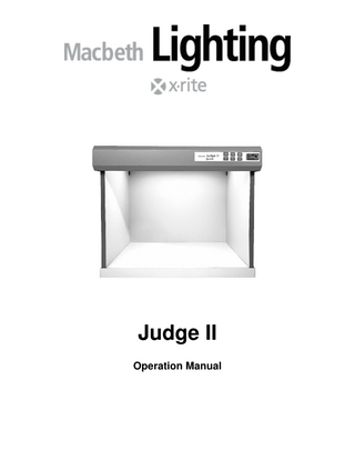
Judge II Operation Manual
CE DECLARATION Manufacturer's Name:
X-Rite, Incorporated
Authorized Representative: X-Rite, Incorporated Siemensstraße 12b • 63263 Neu-Isenburg • Germany Phone: +49 (0) 61 02-79 57-0 • Fax: +49 (0) 61 02 -79 57-57 Model Name/No.:
Judge II
Directive(s) Conformance:
EMC 89/336/EEC LVD 73/23/EEC
NOTE: This is a Class A product. In a domestic environment this product may cause radio interference in which case the user may be required to take adequate measures.
WARRANTY INFORMATION X-Rite products meet the Restriction of Hazardous Substances (RoHS) Directive 2002/95/EC and European Union – Waste Electrical and Electronic Equipment (WEEE) Directive 2002/96/EC. Please refer to www.xrite.com for more information on X-Rite’s compliance with the RoHS/WEEE directives.
FEDERAL COMMUNICATIONS COMMISSION NOTICE NOTE: This equipment has been tested and found to comply with the limits for a Class A digital device, pursuant to Part 15 of the FCC Rules. These limits are designed to provide reasonable protection against harmful interference when the equipment is operated in a commercial environment. This equipment generates, uses, and can radiate radio frequency energy and, if not installed and used in accordance with the instruction manual, may cause harmful interference to radio communications. Operation of this equipment in a residential area is likely to cause harmful interference in which case the user will be required to correct the interference at his own expense.
INDUSTRY CANADA COMPLIANCE STATEMENT This Class A digital apparatus complies with Canadian ICES-003. Cet appareil numérique de la classe A est conforme à la norme NMB-003 du Canada.
EQUIPMENT INFORMATION Use of this equipment in a manner other than that specified by X-Rite, Incorporated may compromise design integrity and become unsafe. WARNING: This instrument is not for use in explosive environments.
Page 2
SAFETY INSTRUCTIONS •
PLEASE READ AND FOLLOW INSTRUCTIONS-Read and follow all instructions before you attempt to assemble or operate the unit.
•
RETAIN THIS MANUAL FOR FUTURE REFERENCE-Once you have read this manual, keep it handy for others to read or refer to when they need to operate the unit.
•
OBEY WARNINGS-Please comply with all warnings and safeguards that we provide in this manual. They have been written to keep you and your unit safe. If the unit is used in a manner not specified in this manual, the protection provided by the unit may be impaired.
•
PROTECT FROM WATER AND MOISTURE-Maintain electrical safety when you use this unit. Do not use it in an area where there is possible hazard of electric shock from spilled water or other liquids or uncontrolled moisture.
•
CLEAN PROPERLY-You can wipe the unit with a clean, white lint-free cloth. Do not apply liquid cleaners or agents containing wax, since these can yellow and change reflectance and gloss properties. Clean outer surfaces with a dampened cloth containing a mild soap.
•
USE ONLY A PROPER POWER SOURCE-Use the proper power source for this unit. If you have any doubt, consult the label on the back of the unit for this information. Unplug the unit when it will not be used for extended periods of time.
•
UNPLUG UNIT BEFORE CHANGING LAMPS-Always unplug the unit before you change lamps.
•
DO NOT OVERLOAD CIRCUITS-Do not overload wall outlets and extension cords. This can result in a risk of fire or electric shock. Periodically examine all cords to make certain that they are not damaged, cracked or twisted. Cords that show any signs of damage or wear should be replaced immediately.
•
AVOID HEAT SOURCES-Do not use the unit near heat sources such as radiators, heat registers or other heat producing appliances.
•
DO NOT OPERATE DURING LIGHTNING STORMS-During a lightning storm, unplug the unit to avoid electrical power surges or unnecessary power drops that could result in damage to lamps and electrical circuitry.
•
SERVICE PROPERLY-With the exception of lamp replacement, do not attempt to service this product yourself. If you should attempt unauthorized repairs, you may invalidate the warranty that is active on your unit. For any other malfunctions in operation, contact X-Rite Technical Service.
•
DAMAGE REQUIRING SERVICE-The unit must be serviced by qualified service personnel when the unit has been dropped or damaged, water or other liquid(s) have been spilled into the electrical components or the unit does not operate normally.
•
UV-A EMISSIONS-A low level UV radiation is emitted when the UV feature is activated. Avoid direct exposure of 15 minutes or more under UV radiation. Protective measures are required for prolonged exposure.
WARRANTY INFORMATION X-Rite, Incorporated (“X-Rite”) warrants each instrument manufactured to be free of defects in material and workmanship for a period of 12 months, unless different local regulations apply. This warranty shall be fulfilled by the repair or replacement, at the option of X-Rite, of any part or parts, free of charge including labor, F.O.B. its factory or authorized service center. This warranty shall be voided by any repair, alteration, or modification, by persons other than employees of X-Rite, or those expressly authorized by X-Rite to perform repairs, and by any abuse, misuse, or neglect of the product, or by use not in accordance with X-Rite's published instructions. X-Rite reserves the right to make changes in design and /or improvements to its products without any obligation to include these changes in any products previously manufactured. Correction of defects by repair or replacement shall constitute fulfillment of all warranty obligations on the part of X-Rite. THIS WARRANTY IS EXPLICITLY IN LIEU OF ANY OTHER EXPRESSED OR IMPLIED WARRANTIES, INCLUDING ANY IMPLIED WARRANTY OF MERCHANTABILITY OR FITNESS FOR ANY PARTICULAR PURPOSE. THIS WARRANTY OBLIGATION IS LIMITED TO REPAIR OR REPLACEMENT OF THE UNIT RETURNED TO X-RITE OR AN AUTHORIZED SERVICE CENTER FOR THAT PURPOSE. This agreement shall be interpreted in accordance with the laws of the State of Michigan and jurisdiction and venue shall lie with the courts of Michigan as selected by X-Rite, Incorporated.
Page 3
INTRODUCTION The Judge II is a lighting booth that can be used for color evaluation under specified lighting conditions. The Judge II feature: • balanced light that conforms to or exceeds published international standards for the visual evaluation of color •
an elapsed time meter
•
“instant-on” capability to eliminate warm-up delays
•
a membrane keypad for rapid switching between illuminants with fingertip control
SPECIFICATIONS DIMENSIONS
Height: 22.25 in (56.5 cm) Width: 27 in (68.6 cm) Depth: 22.25 in (56.5 cm)
WEIGHT/SHIPPING WEIGHT
50 lbs 22.7 kg)/60 lbs (35.1 kg)
ELECTRICAL POWER
100-117 VAC ± 10% 50/60 Hz 220-240 VAC ± 10% 50/60 Hz
Illuminants
Fluorescent Daylight: 7500 K - North Sky Daylight, 6500 K - Avg. North Sky Daylight, 5000 K – Noon Sky Daylight Cool White Fluorescent: 4150 K Typical Store/Office Lighting (Wide Band Fluorescent) Commercial Fluorescent: 3000 K – Ultralume U30, 4100 K – TL84, 3500 K–Ultralume U35 Illuminant A: 2856 K – Typical Home/Accent Lighting (Incandescent) Ultraviolet: Filtered Near UV
SAFETY COMPLIANCE
Pollution Degree: 2 Usage: Indoor Only Altitude: 2000M Transient Overvoltage: Category II
Page 4
VIEWING BOOTH ASSEMBLY 1. Remove from storage and identify all items Figure 1. Note the order in which these items are removed. To pack the unit, you will have to replace each item accordingly. 2. Place the Bottom Panel (#1) on a clean, smooth surface. 3. Position the Rear Panel (#3) bottom notches into the Bottom Panel (#1) rear slots. Fasten the Rear Panel to the Bottom Panel by securing it with two thumbscrews. 4. While supporting the Rear Panel, insert the Left Panel (#2) side tabs into the Rear Panel (#3). Fasten the Left Panel to the Bottom Panel by securing it with the thumbscrew. 5. Insert the Right Panel (#4) side notches into the Rear Panel (#3). Fasten the Right Panel to the Bottom Panel by securing it with the thumbscrew. 6. Place a Tube Cap in each of the four (4) corners of the booth by sliding it into the notch(es) located at the top of each panel. Press the Tube Cap down to seat it. 7. Insert all fluorescent bulbs into the Housing Assembly using Figure 2 on the following pages. Caution! In the following step, DO NOT RELEASE THE HOUSING ASSEMBLY until you are certain that all Tube Caps are properly seated in their sockets. Move your fingers out of the way before you release the Assembly. 8. Lift the Housing Assembly up and place it over the four Tube Caps. Rest it on the two rear Tube Caps and gradually seat the Housing Assembly onto the two front Tube Caps in a hinge-like motion. When you are certain that the Housing Assembly is secure, release it. This completes the Assembly. Proceed to the OPERATION section of this manual.
2 3
4
1
6
5 Figure 1 – Viewing Booth Assembly
Page 5
OPERATION Applying Power to the Assembled Unit 1. Make certain that all lamps are properly seated, and that the unit is placed on a stable, vibration-free surface. 2. Peel off the “CHECK VOLTAGE SETTING PRIOR TO OPERATING UNIT” label located over the female power cord receptacle at the rear of the unit. To check the setting, identify the voltage displayed in the Voltage Indicator Window of the fuse drawer. 3. If the voltage displayed is correct, plug the power cord into the female cord receptacle, then plug the cord into a properly rated wall socket. Proceed to "Selecting a Light Source" below. 4. If the voltage displayed is incorrect, proceed to "Changing the Voltage Selection Unit" below.
Changing the Voltage Selection Unit 1. To remove the Fuse Drawer, grasp and pinch the two latch ribs located at each side of the drawer and slide the unit out. 2. Note the voltage displayed in the window. If a different voltage is needed, grasp and remove the gray Voltage Selection Unit and turn it to display the desired voltage in the Voltage Indicator Window. Reinsert the Voltage Selection Unit into its housing. 3. With both fuses properly seated, slide the Fuse Drawer back into the unit. Gently press the Fuse Drawer until you hear a distinct click. 4. Reconnect the power cord to the unit and apply power. If the unit shows signs that the fuses may have blown again contact your X-Rite Service Representative.
Selecting a Light Source 1. Press the button label: 2. DAY for the daylight source; 3. CWF for the cool white fluorescent source; 4. U30/TL84 for the Ultralume or TL84 source installed in your unit; 5. A for the incandescent source; 6. UV for the ultraviolet source. Note: The ultraviolet source (UV) can be used in combination with any of the light sources or by itself for evaluation of optical brighteners, whitening agents, or fluorescent dyes or pigments. 7. Press OFF to turn one or more selected lamps off.
Page 6
Changing Lamps CAUTION: Unplug the power cord from the power source before you replace the lamps. 1. Check the elapsed time meter located at the right side of the control pad to make certain that 5000 or more hours have elapsed since lamps were installed. We recommend that all lamps be changed after 5000 hours of unit operation. 2. Refer to Figure 2 below to follow the replacement configuration. Replace all lamps. Note: The INC, Tungsten Halogen lamp should not be touched with bare fingers because the oil from the skin will reduce lamp life. 3. Verify that the lamps are replaced properly by illuminating each one separately to make certain that the operating switch turns the desired lamp ON and OFF.
Figure 2 – Lamp Replacement
Fuse Check and Replacement Procedure CAUTION: Unplug the power cord from the unit before checking or replacing the fuses. 1. Locate the Fuse Drawer at the rear of the unit and record the number exposed in the Voltage Indicator Window. This number represents the AC power setting (VAC) and will be one of the following: 100, 120 (117), 220, 240. Note: In the following step, if the Voltage Selection Unit is removed from the Fuse Drawer, reinsert it properly using step 2 in "Changing the Voltage Selection Unit" on the previous page. 2. To open and remove the Fuse Drawer, grasp and pinch the two latch ribs located at each side of the drawer and slide the unit out so that you do not disturb the gray Voltage Selection Unit. 3. Remove and inspect the two fuses. If there is evidence that one or both fuses have blown, replace them with Sloblo® (5mm x 20mm medium time lag) fuses. Use a 1.6 amp fuse for 100 VAC or 117 VAC units; use a 1 amp fuse for the 220 VAC or 240 VAC units. 4. With both fuses properly seated, slide the Fuse Drawer back into the unit. Before you close it, make certain to look at the Voltage Indicator Window to verify the proper voltage is displayed (the voltage noted in step 2). Gently press the Fuse Drawer until you hear a distinct click. 5. Reconnect the power cord to the unit and apply power. If the unit shows signs that the fuses may have blown again contact your X-Rite Service Representative.
Page 7
Parts: Consult your X-Rite Price List for additional Lamp Kit Options or call your local X-Rite office. Judge II (7500 K) 24" Lamp Kit A-LK/JU75
Judge II (5000 K/TL84) Lamp Kit A-LK/JU5084
This kit consists of four (4) F20T12/75 fluorescent daylight lamps. Two (2) required for The Judge II. Sold in packaged of four (4) or as part of a specific lamp kit.
This kit consists of two (2) F20T12/50 fluorescent daylight lamps, one (1) F20T12/CW cool white fluorescent, one (1) F20T8/TL84 narrow band fluorescent used in Europe, one (1) 75 watt halogen illuminant A, and one (1) F20T12/BLB UV lamp.
Judge II (6500 K) 24" Lamp Kit A-LK/JU65
Judge II (7500 K/U30) Lamp Kit A-LK/JU75U30
Same as above except for four (4) F20T12/65 lamps.
This kit consists of two (2) F20T12/75 fluorescent daylight lamps, one (1) F20T12/CW cool white fluorescent, one (1) F20T12/U30 narrow band fluorescent used in US retail, one (1) 75 watt halogen illuminant A, and one (1) F20T12/BLB UV lamp.
Judge II (5000 K) 24" Lamp Kit A-LK/JU50 Same as above except for four (4) F20T12/50 lamps.
Judge II (6500 K/U30) Lamp Kit A-LK/JU65U30
Judge II (7500 K/TL84) Lamp Kit A-LK/JU7584 This kit consists of two (2) F20T12/75 fluorescent daylight lamps, one (1) F20T12/CW cool white fluorescent, one (1) F20T8/TL84 narrow band fluorescent used in Europe, one (1) 75 watt halogen illuminant A, and one (1) F20T12/BLB UV lamp.
This kit consists of two (2) F20T12/65 X-Rite fluorescent daylight lamps, one (1) F20T12/CW cool white fluorescent, one (1) F20T12/U30 narrow band fluorescent used in US retail, one (1) 75 watt halogen illuminant A, and one (1) F20T12/BLB UV lamp. Judge II (5000 K/U30) Lamp Kit A-LK/JU50U30
Judge II (6500 K/TL84) Lamp Kit A-LK/JU6584 This kit consists of two (2) F20T12/65 fluorescent daylight lamps, one (1) F20T12/CW cool white fluorescent, one (1) F20T8/TL84 narrow band fluorescent used in Europe, one (1) 75 watt halogen illuminant A, and one (1) F20T12/BLB UV lamp. Judge II (U35) 24" Lamp Kit A-LK/JUU35 This kit consists of two (2), F20T12/U35 Ultralume 35 Fluorescent lamp, one (1) SPLIII-510 Instruction sheet, one (1) SD43-SPL-U30 Label, and one (1) SD43-SPL-CWF Label.
This kit consists of two (2) F20T12/50 fluorescent daylight lamps, one (1) F20T12/CW cool white fluorescent, one (1) F20T12/U30 narrow band fluorescent used in US retail, one (1) 75 watt halogen illuminant A, and one (1) F20T12/BLB UV lamp. Illuminant A Lamp Diffuser
GM27006570
Power Cord (220/240V)
GM10032100
Power Cord (100/117V)
GM05318311
X-Rite makes no warranty of any kind with regard to the material contained in this manual, including implied warranties or fitness for a particular purpose. X-Rite shall not be liable for errors contained herein or for incidental or consequential damages in connection with the performance or use of this material. This manual is the copyright of X-Rite. Any reproduction of the publication in whole or in part without the express permission of X-Rite is a breach of this copyright. ®
The Judge is a registered trademark of X-Rite, Incorporated.
Page 8
Corporate Headquarters - USA 4300 44th Street SE Grand Rapids, Michigan 49512 Phone 1 800 248 9748 or 1 616 803 2100 Fax 1 800 292 4437 or 1 616 803 2705 Corporate Headquarters - Europe Althardstrasse 70 8105 Regensdorf Switzerland Phone (+41) 44 842 24 00 Fax (+41) 44 842 22 22 Corporate Headquarters - Asia Room 808-810 Kornhill Metro Tower, 1 Kornhill Road Quarry Bay, Hong Kong Phone (+852) 2 568 6283 Fax (+852) 2 885 8610 Please visit www.xrite.com for a local office near you.
P/N 424265 Rev. D