aeros
Aeros-Mobivac-III-Manual
Manual
20 Pages
Preview
Page 1
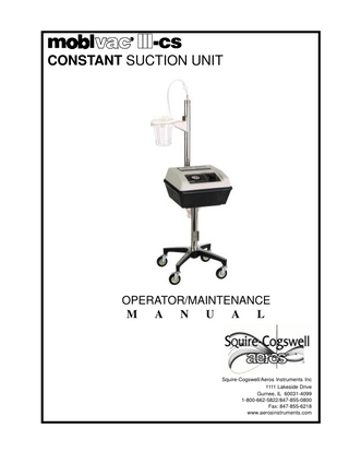
The purpose of the Moblvac® III-cs is to perform all routine constant suctioning procedures. These may include tracheal and oral aspiration, wound and thoracic drainage. The Moblvac® III-cs is also ideal for use within the G.I. lab as well as for backup suction in the O.R. and E.R. departments. The Squire-Cogswell/Aeros Moblvac® III-cs is a constant suction unit designed for use in the hospital, surgery center, and physicians offices. Because of the Moblvac’s constant suction capacities are driven by a fan cooled, rotary carbon vane pump. It comes equipped with a disposable exhaust filter, an in-line suction filter with 14” of tubing, a disposable 1200cc collection canister with mounting bracket, and a preventative maintenance kit.
This manual covers Moblvac® III-cs in the following sections:
1.
INSTRUCTIONS FOR USE...
Page 3
2.
MAINTENANCE ...
Page 6
3.
PERFORMANCE TEST & ADJUSTMENTS...
Page 9
4.
TROUBLESHOOTING ...
Page 10
5.
DEVICE SPECIFICATIONS ...
Page 11
6.
DETAILED DRAWINGS (120 VAC)...
Page 12
7.
DETAILED DRAWINGS (220 VAC)...
Page 16
If, after reading this manual you require additional information, please contact Squire-Cogswell/Aeros Instruments’ Customer Service Department at 800-662-5822 or your local Squire-Cogswell/Aeros distributor.
Squire-Cogswell/Aeros Instruments Inc., (800) 662-5822 - Fax: 847-855-6218 - www.squire-cogswell.com 550107 (Rev.2) 04/2004 2
IMPORTANT: This device is for use only by persons properly trained in medical suction techniques and in the operations of suction equipment. Improper use could cause injury. Thoroughly read this operations manual to familiarize yourself with the Moblvac® III-cs before using the device. DANGER: POSSIBLE EXPLOSION HAZARD IF USED IN THE PRESENCE OF FLAMMABLE ANESTHETICS. 1. INSTRUCTIONS FOR USE PRIOR TO INITIAL USE Upon receiving your new Moblvac® III-cs, perform the following initial tests to ensure that your unit is in good working order and that no damage has occurred during shipment. SET UP INSTRUCTIONS Your Moblvac® III-cs has been shipped with some minor assembly required. A 3/32” Allen wrench is the only tool required. 1.
Visually inspect all components for physical damage that may have occurred during shipping.
2.
After removing all components from their cartons, insert the backpole assembly into the back of the Moblvac® III-cs base.
3.
Align the two “collection mounting brackets” located at the top of the backpole assembly towards the front of the unit.
4.
Tighten the 10-32 set screw located at the back of the base assembly with a 3/32” Allen wrench.
5.
Connect the tubing from the bottom of the backpole to the safety overflow trap assembly.
6.
Plug the power cord into an electrical outlet. Depress the “POWER” switch and listen to verify that the pump starts.
7.
Plug the vacuum port located at the top of the backpole and adjust the vacuum level by turning the vacuum regulator knob. Verify that the vacuum gauge reflects a charge in vacuum level while turning the regulator knob.
8.
Depress the “POWER” switch to turn the unit OFF (O).
9.
Place a collection canister bracket (ring) in the slide mounting bracket of the backpole assembly or pedestal stand and insert a collection canister.
Squire-Cogswell/Aeros Instruments Inc., (800) 662-5822 - Fax: 847-855-6218 - www.squire-cogswell.com 550107 (Rev.2) 04/2004 3
The Moblvac® III-cs will use any collection device. However, if you are not using an Aeros 1200cc disposable collection canister, make sure that the collection device that is being used is equipped with a safety overflow mechanism to protect the pump from accidental overflow. Ensure that you have the appropriate collection device and suction tubing. Depending on the procedure, ensure that you have the appropriate Chest Drainage Unit, Nasal Gastric tube, aspirating tip, or wound drain for patient use. The Moblvac® III-cs is now ready to place into service. OPERATING INSTRUCTIONS Verify that a clean bacteriostatic exhaust filter, in-line suction filter, collection canister, and the necessary tubing are installed on the Moblvac® III-cs. ORAL, NASAL AND TRACHEAL ASPIRATION 1.
Place a clean collection canister in the upper bracket, located on the backpole assembly of your Moblvac® III-cs. Ensure that tubing is connected from the “VACUUM PORT ASSEMBLY” of the Moblvac® III-cs to the “vacuum port” of the collection canister and from the “patient port” of the collection canister to the aspirating tip that is being used.
2.
Open the vacuum port located at the top of the backpole assembly and place your finger over the outlet.
3.
Turn the Moblvac® III-cs ON.
3.
Adjust the vacuum to the desired vacuum level by using the “VACUUM REGULATOR” Knob.
5.
Open the vacuum port located at the top of the backole and proceed with the suction procedure.
PLEURAL DRAINAGE Moblvac® III-cs can be utilized with any “Disposable Chest Drainage Unit” available on the market. Some chest drainage units come with a built in flow adjustment valve and some do not. The Aeros Needle Valve Assembly is available for those units that do not offer this feature. Follow all manufacturers’ directions on the Chest Drainage Unit for its setup and use. Chest Drainage Units Without Built In Flow Adjustment Valves. Place the Chest Drainage Unit in the “optional” Aeros Chest Drainage Unit Bracket. Ensure that tubing is connected from the “VACUUM PORT ASSEMBLY” of the Moblvac III-cs to the Aeros Needle Valve Assembly which is mounted in the collection canister bracket of the backpole. Connect tubing from the Needle Valve Assembly to the vacuum port tubing of the Chest Drainage Unit. OR Squire-Cogswell/Aeros Instruments Inc., (800) 662-5822 - Fax: 847-855-6218 - www.squire-cogswell.com 550107 (Rev.2) 04/2004 4
Chest Drainage Units With Built In Flow Adjustment Valves. Place the Chest Drainage Unit in the “optional” Aeros Chest Drainage Unit Bracket. Ensure that tubing is connected from the “VACUUM PORT ASSEMBLY” of the Moblvac® III-cs to the vacuum port tubing of the Chest Drainage Unit. 1.
Open the vacuum port located at the top of the backpole assembly and place your figer over the outlet.
2.
Turn the Moblvac® III-cs ON.
3.
Adjust the Moblvac® III-cs to a low vacuum setting by using the “VACUUM REGULATOR” knob.
NOTE: The vacuum level provided to the chest cavity is regulated by the Chest Drainage Unit. Setting the Moblvac to a low vacuum level ensures that you are producing sufficient vacuum to properly operate the chest drainage unit. 4.
Open the vacuum port located at the top of the backpole. Adjust the Aeros needle valve or Chest Drainage Unit (per the manufacturers’ instructions) as necessary and proceed with the suction procedure.
REPROCESSING AND CLEANING INSTRUCTIONS 1.
Discard all contaminated parts after any suctioning procedure. These components may include the collection canister, disposable chest drainage unit, in-line filter, exhaust filter, and all suction tubing.
2.
Wipe the surface of the unit clean with a mild antiseptic and a clean soft cloth.
3.
Place a new collection canister, suction tubing, and filters with the Moblvac® III-cs.
4.
Check the air inlet filter at the back of the unit to see that it is clear of any dirt. If cleaning is necessary simply “pop off” the filter cover so the filter can be vacuumed or, if the dirt is excessive, washed in a mild antiseptic and thoroughly rinsed in water. After the filter is completely dried, reinstall the filter and snap the cover back into place.
5.
Inspect the overflow trap assembly for any evidence of an accidental overflow. If an overflow has occurred, use the following guidelines. OVERFLOW - Aspirant has contaminated the overflow trap assembly. Replace and/or clean parts according to procedures described in OVERFLOW CLEANING PROCEDURE on page 6.
Squire-Cogswell/Aeros Instruments Inc., (800) 662-5822 - Fax: 847-855-6218 - www.squire-cogswell.com 550107 (Rev.2) 04/2004 5
SEVERE OVERFLOW - Aspirant has contaminated the overflow trap assembly and the vacuum port tubing. Replace and/or clean external parts according to procedure described in OVERFLOW CLEANING PROCEDURE below. In addition, open the unit to assess the extent of the internal over flow. OVERFLOW CLEANING PROCEDURE NOTE: THESE PROCEDURES ARE ONLY REQUIRED WHEN AN OVERFLOW HAS OCCURRED. 1.
Discard all external contaminated tubing.
2.
Clean the overflow trap assembly by unscrewing the cap and disassembling the various components. Wash all parts with mild antiseptic, dry, reassemble and verify that the float is in the down position and the cap seals tightly on the glass jar.
3.
Replaces all discarded tubing.
4.
If the vacuum port tubing was contaminated, open the unit and inspect the following parts for contamination (See MAINTENANCE section below for opening the unit): All Internal Tubing: If contaminated, replace. Regulator Assembly: If contaminated, clean according to procedure on page 7. Pump Assembly: If contaminated, clean according to procedure on page 8.
2. MAINTENANCE Tools required to service the Moblvac III-cs. (1) Pliers (1) 11/32” nut driver (1) Adjustable wrench (1) Flathead screwdriver
(1) Phillips screwdriver (1) 5/64” Allen wrench (1) 1/16” Allen wrench
CAUTION: NEVER DISASSEMBLE THE MOBLVAC III-cs WHEN THE POWER CORD IS CONNECTED TO AN ELECTRICAL OUTLET. To access the internal components of the Moblvac® III-cs, remove the two (2) Phillips head screws located in the rear of the unit near the back assembly. Tilt the cover forward.
Squire-Cogswell/Aeros Instruments Inc., (800) 662-5822 - Fax: 847-855-6218 - www.squire-cogswell.com 550107 (Rev.2) 04/2004 6
PREVENTATIVE MAINTENANCE Preventative maintenance is recommended every six months. It is up to the user’s discretion to clean the unit more often after frequent use or to lengthen the schedule if use is infrequent. A Preventative Maintenance Kit is available which contains all necessary items and instructions for performing the preventative maintenance procedure. VACUUM REGULATOR REPLACEMENT 1.
Tilt the shroud assembly forward off of the Moblvac® III-cs base (make note of the orientation of all tubing and the regulator body).
2.
Disconnect all three (3) tubing connections from the regulator body.
3.
Use a 5/64” Allen wrench to loosen the set screw on the shaft of the regulator body. Unscrew and remove the vacuum regulator knob from the control panel.
4.
Remove the outside locknut that secures the regulator to the control panel. The regulator can now be removed. (Please note: the depth of the inside locknut on the shaft of the regulator body. This determines the height of the regulator body in the control panel).
5.
Remove the check valve located at the bottom of the regulator body and mount on the new regulator body. (Please note: Upon reinstallation, make sure that the arrow on the body of the check valve points toward the pump. Improper replacement will cut off the vacuum supply.)
6.
To mount the new regulator, first remove the knob from the body by loosening the set screw on the shaft of the body. (Use a 5/64” Allen wrench).
6.
Mount the new regulator body to the control panel making sure the fittings are in the same orientation as the original.
7.
Insert the regulator knob fully into body.
8.
Tighten the set screw until it stops. Then loosen the set screw a 1/4 turn to prevent damage to the shaft of the knob.
9.
Reconnect all tubing.
VACUUM REGULATOR CLEANING 1.
Remove the vacuum regulator assembly as described in the VACUUM REGULATOR REPLACEMENT section above.
2.
Discard all tubing.
Squire-Cogswell/Aeros Instruments Inc., (800) 662-5822 - Fax: 847-855-6218 - www.squire-cogswell.com 550107 (Rev.2) 04/2004 7
3.
Remove the O-rings from the knob. Also, note that the inner rod of the knob can be pulled out for cleaning.
4.
Clean the body, fittings and O-rings in a mild soap solution or isopropyl alcohol and dry all parts completely. Clean only the shaft and the removable inner rod on the regulator knob. Do not allow any water into the knob as it will impede its performance.
5.
Reassemble all components and apply a light coating of a silicone based lubricant (i.e.: Dow Corning 111) to the O-rings.
6.
Reassemble the vacuum regulator and remount the regulator in the Moblvac® III-cs.
7.
Attach new vacuum tubing.
PUMP REPLACEMENT 1.
Disconnect the three (3) pump wires from the PCB and two (2) wires from the capacitor.
2.
Disconnect the tubing from the fittings on the pump.
3.
If necessary, loosen the mounting bracket for the capacitor and remove the capacitor.
4.
Using an 11/32” nut driver, remove the four (4) nuts from the base of the pump. Remove pump.
5.
To mount replacement pump, insert the pump onto the four (4) vibration bumper posts and secure the pump in place.
6.
Connect the pump wires to the PCB and the capacitor.
7.
Reconnect all tubing.
8.
Proceed to PERFORMANCE TEST & ADJUSTMENTS on page 9.
PUMP CLEANING NOTE: The heart of the Moblvac® III-cs is a rotary carbon vane pump. It is NOT recommended that the pump be disassembled for routine cleaning. However, if performance has been affected by the pump becoming contaminated with aspirant, or if an overflow problem has occurred, the following procedure should be performed. 1.
Remove the pump assembly from the Moblvac III-cs as described above in the PUMP REPLACEMENT section.
Squire-Cogswell/Aeros Instruments Inc., (800) 662-5822 - Fax: 847-855-6218 - www.squire-cogswell.com 550107 (Rev.2) 04/2004 8
2.
Remove the three (3) pump head screws located on the pump head.
3.
Remove the cover plate, shim, wear plate and the four (4) vanes.
4.
Wash all exposed areas with an isopropyl alcohol solution.
Before you reassemble the pump make certain that all components are completely dry. Rust is likely to form if any moisture is present. 5.
Replace the vanes, wear plate, shim, and cover plate.
6.
Replace and equally tighten the three (3) pump head screws.
7.
Reinstall the pump assembly.
3. PERFORMANCE TEST AND ADJUSTMENT It is recommended that you verify performance or the Moblvac III-cs after: - An overflow. - Preventative maintenance. - Any maintenance. To verify pump & regulator operation: 1.
Plug the power cord into an electrical outlet. Turn the unit ON and listen to verify that the pump starts.
2.
Open the vacuum port located at the top of the backpole assembly and place your finger over the outlet.
3.
Adjust the vacuum level by turning the vacuum regulator knob. Verify that the vacuum gauge reflects a change in vacuum level while turning the regulator knob. Also verify that you feel vacuum at your finger tip.
4.
Turn the unit OFF.
The following steps will verify the flow and the vacuum specifications: 1.
Connect a suction flow measuring device to the vacuum outlet of the Moblvac® III-cs.
2.
Turn the unit ON.
3.
Adjust the Moblvac® III-cs to full vacuum and verify that both the flow and vacuum specifications match the figures found on page 11 of this manual.
Squire-Cogswell/Aeros Instruments Inc., (800) 662-5822 - Fax: 847-855-6218 - www.squire-cogswell.com 550107 (Rev.2) 04/2004 9
4. TROUBLESHOOTING Problem
Cause
Low or no vacuum on 1. Regulator is turned all the way off. running unit.
Correction 1. Turn regulator knob clockwise to start flow or increase vacuum.
2. An improper tubing connection or crimped tube in the system.
2. Check all external vacuum parts for crimped tubing. If still no vacuum check all internal tubing connections. 3. Mechanical shut-off is activated in 3. If mechanical shut-off has been either the overflow trap assembly or activated on a full canister, replace the the collection canister. canister If the overflow trap assembly has been activated in the safety overflow jar. Follow Overflow Cleaning Procedures on page 6. 4. Vacuum port is plugged. 4. Open vacuum port located at the top of the backpole. 5. Collection canister improperly 5. Check canister for any cracks. Verity installed or defective. that all ports on the canister lid are tight. Pump does not turn on when power switch is depressed.
1. Unit is not plugged in.
1. Plug the unit into an outlet.
2. Faulty electrical connections.
2. Make sure that all wires are secured tightly on the lugs and the lugs themselves are secure on the terminals. 3. Clean pump according to Pump Cleaning on page 8. 4. Replace the pump.
3. Pump has seized.
4. The motor may be worn and cannot deliver the torque required to operate the pump, or the bearing is damaged and is locking the rotor in place. 5. Blown fuse(s). 5. Replace fuse(s). Also check #3 above.
Gauge does not 1. Gauge is either not connected or is register vacuum level. faulty. 2. Blockage in vacuum lines
High noise level.
1. Check that tubing is properly connected between vacuum regulator and gauge. 2. Check that the 2-way solenoid is not stuck in the pen position; or Check Valve is not stuck closed; of that the vacuum regulator is not completely turned off.
1. Unit enclosure is not properly closed.
1. Check that the unit is properly closed. Verify that the outer flanges of the edge trim are not stuck between the enclosures. 2. Pump is running a high pitch. 2. Replace the vanes and clean the pump or replace entire pump. 3. Loose fittings on the exhaust side of 3. Check all fittings on the exhaust side the pump. of the pump for any loose connection. Squire-Cogswell/Aeros Instruments Inc., (800) 662-5822 - Fax: 847-855-6218 - www.squire-cogswell.com 550107 (Rev.2) 04/2004 10
5. DEVICE SPECIFICATIONS PUMP Rotary Carbon vane type. PERFORMANCE Vacuum Range:
Up to 580mm Hg
Free Air Flow:
38 LPM minimum
CONTROLS Vacuum Regulator:
Rotary type on panel.
Vacuum Gauge:
Calibrated in mm Hg
ELECTRICAL REQUIREMENTS AC: 120V, 60Hz, 2A 220V, 50Hz, 2A Fuses:
Slow blow.
COLLECTION DEVICE Canister: Capacity: Tubing:
Disposable plastic with mechanical shutoff. 1200cc standard. 14” with bacterial filter.
PHYSICAL DIMENSIONS Overall Height: Overall Width: Overall Depth: Weight: Warranty:
28” 14” 16” 32 lbs. 3 years
ISO 13485
22.2 No. 125
Certificate No. FM 33489
MEDICAL EQUIPMENT LISTED 544U
220 vac MEDICAL EQUIPMENT CLASSIFIED BY UNDERWRITERS LABORATORIES INC. WITH RESPECT TO ELECTRIC SHOCK, FIRE AND MECHANICAL HAZARDS ONLY IN ACCORDANCE WITH UL 26011, AND C22.2 NO. 601.1 #9N56
Squire-Cogswell/Aeros Instruments Inc., (800) 662-5822 - Fax: 847-855-6218 - www.squire-cogswell.com 550107 (Rev.2) 04/2004 11