Hardware Instructions for Use
42 Pages
Preview
Page 1
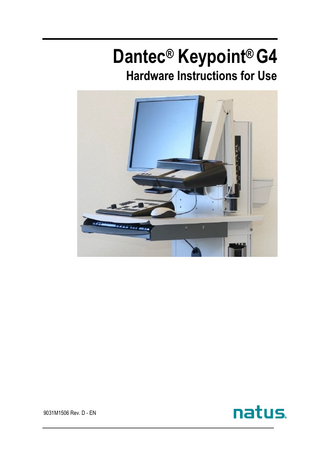
Dantec® Keypoint® G4 Hardware Instructions for Use
9031M1506 Rev. D - EN
Dantec Keypoint G4
Blank page.
2
Hardware Instructions for Use
© 2020 Natus. All rights reserved. Issued 02/2020 The contents of this manual are the property of Natus. Any reproduction in whole or in part is strictly prohibited. At the time of printing / transfer to the DVD, this manual correctly described the device and its functions. However, as modifications may have been carried out since the production of this manual, the system package may contain one or more addenda to the manual. This manual including any such addenda must be thoroughly read, before using the device. The following situation voids any guarantee(s) and obligations for Natus: - The device is not used according to the enclosed manuals and other accompanying documentation. This system is CE marked in conformity with the requirements in the Medical Device Directive 93/42/EEC. Natus Neuro and Keypoint are registered trademarks of Natus Medical Incorporated in the U.S. and in other countries. Note that the documentation accompanying the Keypoint devices includes a Software Instructions for Use manual, a Hardware Instructions for Use manual, a Technical Data Sheet and a Clinical Reference Manual. Both the Software and Hardware Instructions for Use manuals are necessary to be able to use the Keypoint.NET application and carry out a test. For advanced use of the Keypoint.NET application, the Clinical Reference Manual (available in English only) offers a description of all the functions and tests that can be performed. For technical information, the Technical Data Sheet (available in English only) offers detailed technical specifications.
Follow Instructions for Use / Attention to Warnings and Cautions
Before starting a test, make sure you read the documentation and fully understand how to operate the system. Pay special attention to all Warnings and Cautions. For the list of the general regulatory symbols associated with this device, see the General Regulatory Symbols section in this manual.
3
Dantec Keypoint G4
Blank page.
4
Hardware Instructions for Use
Table of Contents Safety Information ... 7 Intended Use ... 7 Contraindications... 7 Side Effects ... 9 Safety Requirements ... 10 Excerpt from the IEC 60601-1 Standard ... 12 System Overview ... 13 Workstation ... 13 Cable Connection Overview... 14 Cable Connections ... 15 Connection Panel ... 16 Power Supply / Isolating Transformer Units ... 17 Technical Specifications ... 17 Controls ... 18 Control Panel ... 18 Control Functions ... 19 Software Navigation / Software Functions... 19 Sweep Speed / Sensitivity Level... 19 Stimulation... 19 Stimulus Intensity / Duration / Repetition Rate ... 20 Loudspeaker / Volume / Cursor Mode / Trace / Marker / Trigger ... 21 Rear Panel ... 21 Footswitch (optional)... 22 Amplifiers ... 23 Amplifier Modules: 3, 4, 6, and 8 Channels ... 23 Rear Panel ... 25 EP Amplifier Module ― 6 Channels ... 26 Stimulators... 28 Safety Information ... 28 Advanced Stimulation Handgrip (optional) ... 29 Constant Current Stimulators ... 31 Additional information related to stimulation ... 32 Power Up Test ... 34 Maintenance ... 35 Safety Checks ... 35 Disposal at the end of operating life ... 36 Classification ... 37 General Regulatory Symbols ... 38 Electromagnetic compatibility ... 39 List of system items, additional and optional parts... 40
5
Dantec Keypoint G4 Blank page.
6
Hardware Instructions for Use
Safety Information The system is intended to be used in electrophysiological tests such as: Electromyography (EMG), Nerve Conduction Studies (NCS) and Evoked Potential (EP) recordings. For safety information related to the patient or the use of the Keypoint.NET application software, refer to the Software Instructions for Use. Make sure to read and understand the information before proceeding to use this equipment.
Intended Use Keypoint G4 is intended as an electrophysiological aid to assess diagnosis and prognosis, and to monitor diseases of the central and peripheral nervous system. It can also be used to study functional aspects of nerves and muscles in other fields such as rehabilitation (physical medicine), occupational medicine and sports medicine.
Contraindications It is a medical decision whether the risk of use clearly outweighs any possible benefit in each case. A patient with an implanted electronic device (i.e., a cardiac pacemaker) should not be subjected to electrical stimulation unless medical specialist opinion has first been obtained. In conditions with bleeding tendency certain care should be taken when needles are used. Conventional precautions should be taken with patients with infectious diseases. Age and sex do not in themselves present contraindications for any procedure. For contraindications with needles / electrodes, refer to their accompanying instructions for use.
Danger Possible explosion hazard, if used in the presence of flammable anesthetics.
7
Dantec Keypoint G4
Warnings Do not use this PC-based equipment for anything else other than what it is intended for by the manufacturer −i.e. carrying out tests on patients and possibly subsequent report generation. Do not install any other software than the Keypoint.NET Software. Natus assumes no responsibility when the equipment is not used as described in this manual. The device is not compatible for use in an MRI magnetic field. The device is not intended for direct cardiac application. The device is not suitable for intensive care monitoring use. Any interruption of the protective earth conductor inside or outside of the device, or disconnection of the protective earth connector is likely to make the device dangerous. Intentional interruption is prohibited. The protective earth (ground) conductor should be checked regularly. Do not connect the "patient ground" to the protective earth connection on the rear panel of the Power Supply Unit/Isolating Transformer or to any other "ground" connections, as the electrode inputs are galvanically isolated. Simultaneous connection of a patient to HF surgical equipment may result in burns at the site of the electrical stimulation or recording electrodes, and possible damage to the electrical stimulator or the electrode input amplifiers. Operation in close proximity (e.g., 1m) to short wave or microwave therapy equipment may produce instability in the electrical stimulator output. Electrical equipment for medical use requires special EMC precautions and needs to be installed and serviced according to the EMC documentation of device. When connecting the integrated LAN port to a network system, the NetBox Ref. 9031G046x must be properly connected into the LAN line between the LAN port and the network system. Do not make a direct connection between the PC LAN Port and the Network System! The NetBox Ref. 9031G046x provides electrical insulation to prevent dangerous electrical current from reaching the patient in the event that the network system becomes accidentally electrically shorted to a high voltage line. Failure to properly install the NetBox Ref. 9031G046x when making the LAN connection annuls this product’s compliance certification with the IEC 60601-1 international safety standards for medical electrical equipment. The use of accessories, electrodes, and cables other than those specified by Natus may result in increased emissions, or decreased immunity of the equipment. Do not use additional multiple socket-outlets or extension cords. Use only optional devices specified by Natus in order to comply with IEC 60601-1. 8
Hardware Instructions for Use
When connecting other equipment, attention must be paid to standard IEC 60601-1 – Medical Electrical Equipment Part 1: General requirements for basic safety and essential performance. Failure to comply with this standard may result in safety risk. The equipment should not be used adjacent, or stacked with other equipment. If adjacent or stacked use is necessary, the equipment should be observed to verify normal operation in the configuration in which it will be used. Dangerous physiological effects! The current stimulator may give off dangerous currents and voltage. When operating the current stimulators, be careful not to expose patients to high currents. Before connecting or disconnecting the stimulation electrode, always “reset” the stimulator. Pay attention to the intensity indicator during the use of the program. –See the section Stimulator Overload in the software user guide, and the section Stimulators in this hardware manual for further information.
Cautions Always use shielded power line cables from Natus to avoid hum line interference, especially near the patient, or the amplifier. Portable and mobile RF communication equipment can affect electrical equipment for medical use. Electric shock hazard. Do not remove the cover. Refer servicing to qualified service personnel. Avoid accidental contact between connected, but unapplied electrodes and other conductive parts including those connected to protective earth. Do not use cleaning detergents, or other cleaning agents based on alcohol, solvent, silicon-based, abrasive and/or flammable substances to clean the equipment.
Side Effects There are no known side effects for procedures performed with Keypoint G4.
9
Dantec Keypoint G4
Safety Requirements CAUTION This device is intended to be used by qualified medical personnel, knowledgeable in the field of neurophysiology and neurophysiological assessment, as well as in the use of the product / Keypoint equipment.
This device has been designed and tested in accordance with IEC Publication 60601-1 Medical Electrical Equipment, cf. the ext on IEC 60601-1 further below in this section. The device has been designed for indoor use at temperatures between +10°C and +35°C (+50°F to +95°F). The mains plug must only be inserted in a mains socket outlet provided with a protective earth contact. It is forbidden to use extension cords. WARNING Any interruption of the protective earth conductor inside or outside of the device or disconnection of the protective earth connector is likely to make the device dangerous. Intentional interruption is prohibited. The protective earth / ground conductor should be checked regularly.
10
Hardware Instructions for Use
Adhere to the following recommendations for safe operation of the device: •
When connecting medical equipment being supplied from an outlet located in a nonmedically used room, or when connecting non-medical electrical equipment to this device, please pay attention to the requirements of IEC 60601-1, Safety Requirements for medical electrical systems, cf. the ext on IEC 60601-1 further below in this chapter.
•
When the device is connected to its mains supply, connectors may be live, and any opening of covers or removal of parts possible only with the aid of a tool is likely to expose live parts.
•
The device must be disconnected from all voltage sources before being opened for any adjustment, replacement, maintenance or repair.
•
Service must be referred to Natus authorized service personnel, except for such works described in this manual as being performed by the operator.
•
Make sure that only fuses with the required rated current and of the specified type are used for replacement. The use of makeshift fuses and the short-circuiting of fuse holders is prohibited.
•
Where more than one piece of equipment is connected to the patient, attention must be paid to the summation of patient leakage currents.
•
Whenever it is likely that the protection has been impaired, the device shall be made inoperative and be secured against any unintended operation. Call qualified service personnel to conduct at least a functional test and a safety check that should include the following: - Insulation test; - Ground continuity test; and - Leakage current test, according to IEC 60601-1.
•
The protection is likely to be impaired if, for example, the device: - Shows visible damage; - Fails to perform the intended function(s); - Has been subject to severe transport stresses.
11
Dantec Keypoint G4
Excerpt from the IEC 60601-1 Standard CAUTION When connecting other equipment, qualified attention must be paid to the following excerpt from the medical safety standard to which this system complies.
IEC 60601-1 Medical Electrical Equipment, Part 1: General Requirements for Basic Safety and Essential Performance. Chapter 16: Medical Electrical Systems. When connecting to a medical appliance with an F-type applied part, or some additional equipment complying not with IEC 60601-1 but with the relevant safety standard for such equipment, the additional equipment: 1) must either be placed outside the patient environment (the patient environment is any area in which intentional, or unintentional contact can occur between patient and parts of the system (e.g. a printer), or as a result of some other person touching parts of the system); or 2) if placed within the patient environment, must be: a) provided with an additional protective earth connector; or b) supplied from an extra separating transformer, limiting the enclosure/touch leakage current to a value not exceeding: Normal Condition: 0.1 mA or Single Fault Condition 0.5 mA. Please refer to IEC 60601-1 for further details.
12
Hardware Instructions for Use
System Overview Workstation
(1) Computer
(2) Power Switch
(3) Monitor
(4) Internal Speaker
(5) Control Panel
(6) PC Keyboard
(7) Electrode Arm (optional)
(8) Current Stimulator (optional)
(9) Amplifier Box (optional)
(10) Connection Panel
(11) Accessory Box Kit (optional)
(12) Mouse
(13) Printer (optional)
(14) LAN Socket (optional)
(15) Cart
(16) Power Supply / Isolating Transformer
NOTE All the positions of the devices shown on the picture are examples only.
13
Dantec Keypoint G4
Cable Connection Overview
A Power Supply / Isolating Transformer
F Screen
K Loudspeaker
B Printer (optional)
G Amplifier Box (optional)
L Network Isolator (optional)
C Computer
H Stimulator Box (optional)
M Cart Enclosure
D PC Keyboard
I
N DC power supply unit (used with Isolating Transformer)
E Control Panel
J Connection Panel
Mouse
14
O EP Amplifier Box (optional)
Hardware Instructions for Use
Cable Connections Before operating the device, the system parts should be connected. 1. Connect all the signal interface cables as depicted in the illustration (black thin). 2. Connect all the power interface cables as depicted in the illustration, except for the main cables to the wall outlet (blue dotted). 3. Check voltage: - On the Power Supply unit, make sure that the voltage selectors are set to the proper voltage settings. - On the Isolating Transformer unit, make sure that the correct voltage type is used. 4. Connect the mains cable to the wall outlet (blue dotted). 5. Press the Power on/off button
on the front panel of the computer for the system to turn on.
CAUTION Use only optional devices specified by Natus in order to comply with IEC 60601-1. CAUTION Always use shielded power line cables from Natus to avoid hum line interference, especially near the patient, or the amplifier. NOTE Unplugging the power line cable from the mains input on the power supply/Isolating Transformer disconnects the mains power of the complete system. NOTE Make sure the device connected to the wall power outlet is positioned in such a way to allow easy disconnection from the mains, if needed. NOTE HS LINK – Multiple types of modules can be connected to HS LINK (see G, H, and O in the figure above). Certain types of module combinations are restricted due to HS LINK power limit. Module restrictions are software controlled. NOTE HS LINK – Modules (G, H, and O) connected to HS LINK may have certain limitations due to system power consumption conditions. Limitations are hardware related and can be avoided by using the DC Power Supply (N).
15
Dantec Keypoint G4
Connection Panel
Input / Output Connector Input / Output Magnetic Stimulation / tendon hammer, or synchronization of external trigger, or external stimulation acquisition.
Footswitch Connector
VEP
Pattern Stimulator Connector
AEP
Auditory Stimulation Headset Connector
VEP
Visual Goggles Stimulator Output Connector
Power ON Indicator
16
Hardware Instructions for Use
Power Supply / Isolating Transformer Units For detailed instructions, refer to the Power Supply or Isolating Transformer manual accompanying the units. WARNING Do not use additional multiple socket-outlets or extension cords. CAUTION Use only the 6-outlets safety power supply / isolating transformer unit for all devices of the complete system in order to comply with the IEC 60601-1. -See the Power Supply / Isolating Transformer accompanying manual for detailed instructions for use.
Power Supply
Isolating Transformer
Technical Specifications For technical specifications, refer to the Keypoint G4 section in the Technical Data Sheet.
17
Dantec Keypoint G4
Controls Control Panel
(1) Standby Indicator
(2) Power ON Indicator
(3) Numeric Keypad
(4) Software Navigation Keys
(5) Sweep Speed/Sensitivity Level Arrow Keys
(6) Stimulation Intensity Control Knob
(7) Reset Stimulation Intensity key
(8) Stimulation Duration Arrow Keys
(9) Stimulation Repetition Rate Arrow Keys
(10) Stimulation Indicator
(11) Single Stimulation Key
(12) Repetitive Stimulation Key
(13) Trace/Marker and Trigger Arrow Keys
(14) Volume Indicator
(15) Volume/Cursor Control Knob
(16) Cursor Mode Indicator
(17) Loudspeaker Mute Key / Indicator
(18) Software Function Keys
18
Hardware Instructions for Use
Control Functions Software Navigation / Software Functions Software Navigation Keys – Color Coded The Software Navigation keys allow you to navigate through the application tabs. The 6 Software Navigation keys’ colors and functions correspond to those of the Software Navigation buttons on the application The Left and Right arrow keys and the Enter key allow you to select tests.
Software Function Keys – Color Coded The Software Function keys allow you to control the different software functions on the application. The 12 Software Function keys’ colors and functions correspond to those of the Software Function buttons on the application.
Sweep Speed / Sensitivity Level Sweep Speed Arrow Keys The Right and Left arrow keys allow you to modify the sweep speed. The Right arrow key increases the sweep speed. The Left arrow key decreases the sweep speed.
Sensitivity Level Arrow Keys The Up and Down arrow keys allow you to modify the level of sensitivity. The Up arrow key increases the sensitivity level. The Down arrow key decreases the sensitivity level.
Stimulation Stimulation Indicator The Stimulation indicator green light (LED) blinks once for Single Stimulation, and intermittently for Repetitive Stimulation.
19
Dantec Keypoint G4 Single Stimulation Key When the Single Stimulation key is pressed, a single stimulus is released, and the indicator blinks once. The Single Stimulation key can also be used to stop Repetitive Stimulation.
Repetitive Stimulation Key When the Repetitive Stimulation key is pressed, repetitive stimulus is released and the indicator blinks intermittently. To stop repetitive stimulation, press either the same Repetitive Stimulation key, or the Single Stimulation key.
Stimulus Intensity / Duration / Repetition Rate Stimulation Intensity Control Knob The Stimulation Intensity control knob allows you to adjust the intensity of the stimulation released. Rotate the knob to the right to increase the stimulation intensity. Rotate the knob to the left to diminish the stimulation intensity.
0mA
Reset Stimulation Intensity Key Press the Reset Stimulation Intensity key to reset the stimulation intensity to its base level. WARNING: When operating the current stimulators, be careful not to expose the patient to high currents. Before connecting or disconnecting the stimulation electrode, always reset the stimulator.
Stimulation Duration Arrow Keys The Stimulus Duration Up and Down arrow keys allow you to increase/decrease the duration of the stimulation. The Up arrow key increases the stimulation duration. The Down arrow key decreases the stimulation duration. Stimulation Repetition Rate Arrow Keys The Stimulus Repetition Rate Up and Down arrow keys allow you to increase/decrease the stimulation repetition rate. The Up arrow key increases the stimulation repetition rate. The Down arrow key decreases stimulation repetition rate.
20