Allied Healthcare Products
EPV200 Instruction Manual Rev A Feb 2011
Instruction Manual
20 Pages
Preview
Page 1
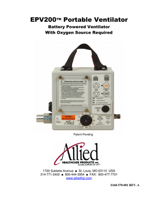
EPV200™ Portable Ventilator Battery Powered Ventilator With Oxygen Source Required
Patent Pending
1720 Sublette Avenue ■ St. Louis, MO 63110 USA 314-771-2400 ■ 800-444-3954 ■ FAX: 800-477-7701 www.alliedhpi.com S168-570-001 REV. A
Table of Contents Section 1 2 3 4 5 6 7 8 9 10 11 12 13 14 15 16 17 18 19
Description Product Description Product Intended Use Explanation of Warnings Explanation of Abbreviations Specifications Features Operating the Ventilator Alarms Battery Replacement Cleaning Maintenance and Schedule Check-out Procedure Accessories Warranty Oxygen Cylinder Depletion Times Symbols Applicable Standards Approximate Settings Based on Patient Height Attaching EPV200 to Equipment
Page 2 2 2 2 3 4 5-7 8 9 9 - 10 10 - 11 12 13 13 14 - 15 15 16 17 - 18 19
Model: EPV200 - Emergency Portable Ventilator with Assist Control
1
1
Product Description
The EPV200 is an internal battery powered, electronically controlled, portable ventilator that requires a 50 psi oxygen source to operate. The EPV200 has selectable tidal volumes, BPM and inspiratory times based on the intended patient’s respiratory requirements. 2
Product Intended Use
The EPV200 is intended to be used as an electronically controlled gas powered emergency ventilator to provide emergency respiratory support by means of a face mask or tube inserted into the patient’s airway. This ventilator is intended for use on patients weighing greater than 20 kg (44 lbs). This ventilator is intended to be used in the environments associated with emergency medical services (EMS), inter-hospital transport and hospital facility usage. This ventilator is intended to be used in temperatures of -9 to 50°C (15 to 122°F) and 5% - 95% relative humidity, non condensing. Biocompatibility testing has proven this ventilator to be safe for periods up to 14 days of continuous use. Results beyond this length of time are not known. CAUTION: Federal law restricts this device to sale by or on the order of a physician. CAUTION: The EPV200 should not be used on children with a weight of 20 kg (44 lbs) or less. 3
Explanation of Warnings Warning: Potential injury to the patient or operator exists.
Caution: Potential damage to the ventilator, breathing circuit or other equipment may result. Warnings and cautions should be read and understood before operating the ventilator. 4
Explanation of Abbreviations Tv BPM It psi cm H2O kPa ml LPM mm LED CPR HPA RH
Tidal Volume Breaths per Minute Inspiratory Time Pounds per Square Inch Centimeters of Water Kilopascal Milliliters Liters Per Minute Millimeters Light Emitting Diode Cardio Pulmonary Resuscitation High Pressure Alarm Relative Humidity 2
5
Specifications
A. B.
Gas Supply Pressure: 280 kPa (40.6 psi) to 600 kPa (87 psi) oxygen DISS Breaths Per Minute (BPM): Accuracy: ±10% BPM Range: 1 second inspiratory time = 0 and 5 to 30 BPM Range: 2 second inspiratory time = 0 and 5 to 20 Tidal Volume (Tv): Accuracy: ±10% with 100% oxygen Tidal volume range 1 second inspiratory time = 200 ml to 600 ml Tidal volume range 2 second inspiratory time = 400 ml to 1200 ml Inspiratory Time (It): Accuracy: ±10% 1 second or 2 second selection Safety Pressure Relief: Fixed at a maximum of 60 cm H2O Low Source Gas Alarm: Activates at 275 to 241 kPa (40 to 35 psi) source pressure. High Airway Pressure Alarm Electronic: Activates at 45 cm H2O. Alarm sound level is greater than 58 decibels. Breath Delivery Alarm: Activates if the airway pressure does not go above 9 cm H2O during a span of 15 seconds, or if a spontaneous breath is detected. Battery Life: Greater than 48 hours at room temperature (10 BPM and 2 seconds It) Oxygen Inlet Filter: 65 micron sintered bronze Leakage: The unit shall be designed so that pressurized oxygen is not allowed to leak through any seals or fittings. Gauge: 0-99 cm H2O accuracy ± 5% or 1 cm H2O, whichever is greater Inspiratory and Expiratory Resistance: 5 cm H2O (.5kPa) maximum Inadvertent PEEP: < 2 cm H2O Inadvertent Continuing Expiratory Pressure: < 2 cm H2O Dead Space: < 5.5% of minimum tidal volume Weight: 1.4 kg (3.1 lbs.) with batteries Size: 3.5 x 7.0 x 9.3 (88.9 x 177.8 x 236.2 mm) Operating Conditions: -9 to 50°C (15 to 122°F) 5% - 95% RH non condensing Storage Conditions: -40 to 60°C (-40 to 140°F) 5% - 95% RH non condensing Shipping Conditions: -40 to 60°C (-40 to 140°F) 5% - 95% RH non condensing Breathing mode: Assist Control with ≤2 cm H2O required to trigger a spontaneous breath.
C.
D. E. F. G. H.
I. J. K. L. M. N. O. P. Q. R. S. T. U. V.
Latex Free: This product does not contain Latex.
3
6
Features
3 14 7 5
5 5
2
12 11 9
10 5
13 6 5
8 4
5
5
1 5
Item # 1 2 3 4 5 6
Description Tidal Volume Control Inspiratory Time Control BPM Control Oxygen Inlet Airway Pressure Display Power On/Off Switch
Item # 8 9 10 11 12 13
7
Battery Compartment
14
4
Description Anti-Suffocation Valve Patient Circuit Connection High Airway Pressure Alarm Low Source Gas Alarm Low Battery Alarm Breath Delivery Alarm if Flashing BPM Display
7
Operating the Ventilator Warning: This device should be operated only by qualified personnel under approved medical direction. Warning: Use only as directed. Improper usage or unauthorized modification of this product may result in user or patient injury. Warning: Unit is not MRI compatible. Warning: Not for use in a toxic environment or in the presence of flammable anesthetics.
●
Connect to an oxygen source: Located on the right side of the ventilator and marked with text is a diameter index safety system (DISS) fitting. Connect a 50 psi oxygen source with a minimum of 40 LPM flow capacity to this fitting. The unit comes with a single use supply hose made of PVC. A rubber reusable hose may be purchased and is recommended. See accessories. Warning: Proper tidal volumes may not be provided with a gas source not meeting the specified requirements on page 4. Warning: This device operates with medical gases under pressure, including oxygen. Do not use this device while smoking or near open flames or flammable materials. Caution: In order to provide optimal performance, check all gas supplies to assure that only clean, dry gas that is free of contaminants and/or liquids is used. The gas source may also be a high flow air/oxygen blend meeting the flow and pressure requirements. ●Select the proper inspiratory time:
Press the ON/OFF button to activate the unit. The EPV200 has the options of a 2 second inspiratory time (this is used on adults with tidal volume requirements of more than 600 ml) and a 1 second inspiratory time (this is used on children or adults). Push the appropriate Inspiratory Time button and a green LED will show the selected inspiratory time. Select the desired breaths per minute (BPM): The EPV200 has a BPM range of 0 and 5 to 20 with a 2 second inspiratory time, and a BPM range of 0 and 5 to 30 with a 1 second inspiratory time. Use the up and down arrows above or below the text “BPM” to set the desired BPM. The BPM setting will be displayed in the window above the selection arrows. The 0 BPM setting is used when the patient is breathing spontaneously. The American Heart Association Guidelines 2005 recommend a BPM rate of 8 to 12 for an adult and 12 to 20 for a child. These are recommendations. Physician or medical director instructions should always be followed.
5
Select the desired tidal volume (Tv): Turn the tidal volume knob to the desired tidal volume setting. The flow to the patient is different for each tidal volume. Tidal Volume Setting
Approximate Flow (LPM)
It = 1 second It = 2 second 200 400 240 480 280 560 320 640 360 720 400 800 440 880 480 960 520 1040 560 1120 600 1200
12 14.4 16.8 19.2 21.6 24 26.4 28.8 31.2 33.6 36
Verify the pressure relief setting: This unit has a factory set pressure relief setting of less than 60 cm H2O. The 60 cm H2O setting is a maximum, regardless of vent settings. The pressure relief setting will vary slightly with tidal volume setting. Lower tidal volumes will have a slightly lower pressure relief point. Always verify the relief pressure after the vent settings have been selected. To check the actual relief pressure, block the end of the ventilator breathing circuit and observe the reading on the airway pressure gauge. This will be the maximum airway pressure. You should hear an audible alarm and see a flashing light as this maximum pressure is reached. Warning: Preset tidal volumes may not be delivered when the maximum pressure limit is reached. Inspiratory times will remain constant. However, no additional tidal volume will be delivered after the pressure limit is reached. Connect the patient breathing circuit: Located on the left side of the unit is a 22 mm connection for a patient breathing circuit. The patient breathing circuit has been designed to fit with an oxygen mask (22 mm outside diameter) or an endotracheal tube (15 mm inside diameter). Install the corrugated tubing over the connector so that it is on securely. Follow the established guidelines for maintaining the patient’s airway.
6
Verify the patient is receiving good ventilation: Once the patient is connected to the ventilator, the patient should be observed to make sure he has adequate chest rise and fall. The chest rise should be even and should return to a normal position. If the patient does not have adequate chest rise, check the tidal volume setting and patient connections and examine the patient for a possible obstruction of the airway or other injury. The patient should be monitored to make sure he is receiving proper ventilation. The airway pressure gauge should be observed to make sure the patient is receiving adequate positive pressure ventilation. If the gauge reading is low during the delivery of a breath and the chest rise is also low, check the tidal volume setting and patient connections and examine the patient for a possible obstruction of the airway or other injury. The gauge reading should also be observed to make sure it is not too high. Common numbers used in practice are a maximum of 20 cm H2O for an unprotected airway and 30 cm H2O for a protected airway. Higher pressures may be required based on the patient’s condition. Physician instructions should always be followed. A high reading with a pressure limit alarm may indicate a blocked airway or a stiff lung. If you are using a PEEP valve with the ventilator circuit, the PEEP pressure will not be displayed on the gauge (Airway Pressure Display). ● Spontaneous breathing by the patient:
Should the patient begin to breathe spontaneously, the EPV200 will sense this breath and deliver the set tidal volume at the corresponding inspiratory time. The breath timing will be reset based on the selected BPM rate. For example, if 10 BPM was selected, the next breath will be delivered 6 seconds after the start of the spontaneous breath. The gas flow rate to the patient during a spontaneous breath is based on the tidal volume selection as shown in the table on page 7. Should the patient demand exceed the gas flow rate, the additional demand will be supplied by the ambient air. Ambient air is pulled in through an anti-suffocation valve located in the breathing circuit connection fitting. Warning: Do not cover or block the anti-suffocation valve. Warning: Should a mechanical problem develop or the patient appears to be experiencing difficulty breathing while connected to the unit, disconnect the unit immediately and ventilate by other means. Cold temperature operation: Operating time will be significantly reduced if the batteries are stored at low temperatures. At 15°F (-9°C) the battery life will be approximately 9 hours (10 BPM and 2 second It) before the low battery indicator turns on. The low battery indicator will still give about a 2 hour low battery warning. Batteries should be replaced when the low battery indicator appears, as run times are reduced at low temperatures. When the unit stops operating you will receive a breath delivery alarm. Warning: Batteries stored at temperatures below 15°F (-9°C) may not have enough power to properly operate the solenoid valve in the unit, resulting in tidal volumes that are not the indicated value. 7
8
Alarms
This ventilator contains several alarms: high airway pressure, low source gas, low battery, and breath delivery failure. The high airway pressure alarm is an audible alarm with a red LED that is actuated when the airway pressure during inspiration reaches 45 cm H2O. The safety pressure relief will actuate at pressures between the alarm setting and 60 cm H2O. Warning: Preset tidal volumes may not be delivered when the maximum pressure limit is reached. Inspiratory times will remain constant. However, no additional tidal volume will be delivered after the pressure limit is reached. This alarm is automatically cleared when 25 seconds pass without a high airway pressure being detected. The low source gas alarm is an audible alarm with a red LED that activates when the source gas pressure drops below 40 to 35 psi. This is an indication that the unit will stop functioning soon and that the unit may not be delivering proper tidal volumes. Warning: Preset tidal volumes may not be delivered when the low source gas pressure is reached. This alarm clears when proper source gas pressure is restored for 15 seconds. The low battery alarm is a red LED that indicates the battery is running low. The unit will operate for approximately 2 hours after the alarm first turns on. The batteries should be replaced when the low battery alarm turns on. Warning: The displays on the unit will stay on after the unit has stopped delivering breaths. Batteries should be replaced when a low battery condition is encountered. This alarm clears when the batteries have proper battery voltage. The breath delivery alarm is a flashing red LED. This alarm uses the same light as the high airway pressure alarm. The breath delivery failure alarm will sound when the airway pressure does not reach 9 cm H2O in 15 seconds or when a spontaneous breath is detected. This alarm may indicate that the patient has become disconnected from the unit or the unit has stopped delivering breaths. This alarm clears when airway pressure exceeds 9 cm H2O. Silence Button – When an alarm occurs, the user may press the button for the currently selected inspiratory time for 3 seconds to silence the alarm. This will turn off the buzzer for 110 seconds as long as there are no other alarms. Pressing this button will not clear the alarm LEDs.
8
9
Battery Replacement
Loosen screws on battery door in 4 places
Positive (+) end of battery towards the top of the unit. The batteries are replaced by loosening the 4 thumbscrews on the battery door located on the front of the unit. The batteries should be removed by gently prying the top (+) of the battery up and toward the bottom of the unit. Replace the batteries with 2 D size alkaline batteries only. Do not mix new and old batteries when installing in unit. The batteries must be inserted with the positive (+) end of the battery toward the top of the unit. For ease of installation, install the bottom (-) of the battery first. Replace the battery door and tighten the 4 thumbscrews. Turn the unit on and verify that the displays turn on. Connect a 50 psi oxygen source to the unit and verify that the unit does deliver breaths. The breath delivery alarm will sound if the unit is not connected to a test lung. This is normal and not a concern. The ventilator is now ready for use. Always turn the ventilator off when not in use to preserve battery life. The ventilator does not turn off automatically. Warning: Do not recharge alkaline batteries.
10
Cleaning
The EPV200 should be cleaned after each use. To clean the EPV200, keep the gas supply hose on the unit to prevent contamination of the oxygen circuit. Warning: Cleaning procedures should be performed in an environment free of oil and petroleum based products. The EPV200 has been designed to be water resistant, but the unit cannot be submerged or sprayed down for cleaning. Wipe the unit with a damp rag containing a mild detergent to remove any residue from the surface. Once the residue has been removed, the unit may be wiped with isopropyl alcohol or a cold disinfecting solution to kill bacteria. The unit should then be wiped with water to remove any film left by the cold disinfecting solution. Make sure the unit is dry before putting the unit away.
9
Following is a list of tested cleaning solutions: Isopropyl Alcohol: 70% IPA Alconox: 1 tablespoon Alconox to 1 gallon H2O Cetylcide: 2 tablespoon Cetylcide to 1 gallon H2O Bleach: 10% bleach in H2O Dispose of single patient use items per local biohazard standards. 11
Maintenance and Schedule
The EPV200 should be checked annually to insure proper function. Batteries should be replaced if they are beyond the expiration date on the battery. Replace with D size alkaline batteries. Year 1: Perform Yearly Verification of function and Calibration procedure. Check battery expiration date; replace batteries as necessary. Year 2: Perform Yearly Verification of function and Calibration procedure. Check battery expiration date; replace batteries as necessary. Replace disposable O2 inlet hose with 6 foot oxygen hose (see Accessories on page 14). Replace main valve with piston, o-ring, and spring for units manufactured before April 2009. The manufacturing date is coded into the serial number for each unit. The first four digits identify the year of manufacture, and the next two digits identify the month of manufacture. Example: the serial number 20090403001 was manufactured in the year 2009 and in the month of April. All repairs should be performed by Allied Healthcare Products trained and certified technicians. Year 3: Perform Yearly Verification of function and Calibration procedure. Check battery expiration date; replace batteries as necessary. Year 4: Perform Yearly Verification of function and Calibration procedure. Check battery expiration date; replace batteries as necessary. Year 5: Perform Yearly Verification of function and Calibration procedure. Check battery expiration date; replace batteries as necessary. The unit has a life expectancy of 5 years based on normal usage and proper maintenance. A comprehensive rebuild will be necessary at this time, and should be performed by Allied Healthcare Products trained and certified technicians.
10
Yearly Verification of function and Calibration: Equipment Required Certified gas flow analyzer, capable of measuring BPM, inspiratory time and tidal volume Regulated 50 psi oxygen source New batteries 36 inches of 22 mm corrugated tubing or the allied patient circuit provided. Procedure Connect the 50 psi oxygen source to the oxygen inlet connector. Connect the 22 mm corrugated tubing to the patient circuit connection valve, and the other end to the gas analyzer. Turn the tidal volume, inspiratory time and BPM to the values indicated in the table below. Monitor the values to evaluate acceptability of the unit. Inspiratory Inspiratory BPM BPM Tidal Tidal Time Time Acceptable Setting Acceptable Volume Volume Setting Values Value Setting Acceptable (seconds) (seconds) (ml) Value (ml) 2.0 1.8 - 2.2 20 18 -22 400 360 - 440 2.0 1.8 - 2.2 10 9 - 11 800 720 - 880 2.0 1.8 - 2.2 10 9 - 11 1200 1080 -1320 1.0 0.9 – 1.1 30 27 - 33 200 180 - 220 1.0 0.9 – 1.1 20 18 - 22 400 360 - 440 1.0 0.9 – 1.1 20 18 - 22 600 540 - 660
To test pressure relief, turn tidal volume to 640 ml, block the patient end of the 22 mm corrugated tubing or patient circuit while monitoring the airway pressure display. The airway pressure should not exceed 60 cm H2O. The High Airway Pressure alarm should sound and a red LED should be activated. To test the breath delivery failure alarm, remove all obstructions from the patient circuit connection valve and allow the ventilator to cycle. The breath delivery alarm should sound, and a red LED should be flashing. To test the low source gas alarm, reduce the inlet pressure source to below 35 psi. The low source gas alarm should sound and a red LED should be flashing.
Should the unit fail any of these tests, contact the Allied Healthcare Products, Inc., Technical Support Center in St. Louis: 314-771-2400 or 800-411-5136.
11
12
Check-out Procedure
The unit should be checked for proper operation before each use. This can be done after cleaning to prepare the unit for the next use. Set the ventilator to the following settings: BPM = 10 Tidal Volume = 640 Inspiratory Time = 2 seconds General Operation Check: 1. Connect a 50 psi oxygen source to the unit and turn the power on. The unit should begin to cycle. 2. Using a stop watch, count the number of breaths delivered in 1 minute (60 seconds). Confirm that between 9 and 11 breaths have been delivered. Confirm that the inspiratory time is significantly shorter than the expiratory time. (At the settings noted above, the ventilator should provide a 2.0 second inspiratory time and a 4.0 second expiratory time.) 3. Connect the 22 mm corrugated tubing or the allied patient circuit provided, to the patient circuit connection port. (See Item 9 Under Features On Page 4). Block the patient end of the corrugated tubing. Confirm that the airway pressure does not exceed 60 cm H2O by monitoring the airway pressure display on the face of the ventilator. An alarm will sound at approximately 45 cm H2O. 4. Visually inspect the anti-suffocation valve in the patient circuit connection port to verify that the valve is flush to the contour of the round inner surface and that no gap exists. Alarm Mode Check: 1. Low source gas: Reduce the source gas pressure to below 35 psi and monitor that the red LED display turns on and an audible alarm sounds. Return the source gas pressure to 50 psi, and the alarm should clear in 15 seconds. 2. High airway pressure: Block the patient circuit connection port, and monitor the red LED display for high airway pressure, and an audible alarm will sound. The mechanical pressure relief should limit the airway pressure to less than 60 cm H2O. 3. Breath delivery: Clear the patient circuit connection port and allow the ventilator to cycle for at least 20 seconds. The airway pressure display should not exceed 9 cm H2O for 15 seconds. Monitor that the red LED is flashing on the breath delivery failure alarm, and an audible alarm will sound. Should the unit fail any of these tests, contact Allied Healthcare Products, Inc., Technical Support Center in St. Louis: 314-771-2400 or 800-411-5136.
12
13
Accessories Description 6-foot Oxygen Hose Oxygen Regulator 3-foot Ventilator Circuit with Swivel, Adult Mask and Filter (case of 10) Adult Oxygen Mask (case of 10) Child Oxygen Mask (case of 10) PEEP Valve* (case of 12) Hook & Loop Strap (case of 15)
Part Number L535026 L270-220 L599-130
L595161-10 L595162-10 LPEEP L770-CPR-VEL
*When using a PEEP valve, the airway pressure display will not show the PEEP pressure. 14
Warranty
LIMITED ONE (1) YEAR WARRANTY Allied Healthcare Products, Inc.(Allied) warrants this product to be free from defects in material and workmanship for a period of (1) year from the date of manufacture. This Warranty is expressly conditioned on compliance with all inspection and preventative maintenance requirements as set by applicable government agencies and as specified by Allied.
Disclaimer of Other Warranties: THIS WARRANTY IS IN PLACE AND IN LIEU OF ALL OTHER WARRANTIES OR REPRESENTATIONS, EXPRESSED OR IMPLIED, INCLUDING, BUT NOT LIMITED TO, WARRANTIES OF MERCHANTABILITY OR FITNESS FOR SPECIFIC PURPOSE, BY OPERATION OF LAW OR. OTHERWISE.
This Warranty is extended by Allied only to the first purchaser of the product from either Allied or from an authorized Allied distributor.
This Warranty does not apply to malfunction or damage resulting from accident, alteration, misuse of the product, improper preventative maintenance, storage at extreme temperatures or extreme environments beyond design limits, or, where appropriate, improper use of the product by untrained persons. This Warranty does not apply to any plastic or rubber components since they can be affected adversely by undue exposures to heat, sun, water, ozone, or to other deteriorative elements.
ALLIED’S OBLIGATIONS AND PURCHASER’S REMEDIES UNDER THIS WARRANTY ARE LIMITED AS FOLLOWS: In the event of a defect, malfunction, or failure to conform to this Warranty, purchaser shall return this product to Allied with shipping charges prepaid, within a reasonable time after discovery of such defect, malfunction or failure to conform. Allied shall repair or replace (at Allied’s option) this product if it is defective, malfunctions or fails to conform to this Warranty, and shall return it to purchaser with shipping charges prepaid and without any additional charges due to costs of repair or replacement.
Allied has not authorized any other firm or person to make any representations concerning this product nor to assume on Allied’s behalf any liability in any way connected with the sale or use of this product.
In the event the product returned by purchaser is not defective, has not malfunctioned and does conform to this Warranty, Allied shall not be obligated to repair or replace the product and shall not be obligated for shipping charges for return of the product to the purchaser.
This Warranty becomes void immediately should any repairs of, or alterations to this warranted product be made without authorization by Allied.
Allied shall in no event be liable for any consequential damages, nor for loss, damages or expenses directly or indirectly arising from the use of this product.
13
15
Oxygen Cylinder Depletion Times
These times are approximate and assume full cylinder capacity. Always monitor the cylinder pressure and low pressure alarm to make sure you do not run out of oxygen. E Cylinder
1200 1000 800 600 500 400 300 200
Capacity =
682
Liters Oxygen Capacity (4.6 Liters Water Capacity) Breaths Per Minute
8
9
10
12
14
15
18
20
22
24
26
28
30
67 80 98 127 149 180 225 293
60 72 88 115 135 163 206 274
54 65 80 104 123 149 189 256
46 54 67 88 104 127 163 225
39 47 58 76 90 111 143 200
37 44 54 72 85 104 135 189
60 72 88 115 163
54 65 80 104 149
50 59 73 96 137
46 54 67 88 127
42 50 62 82 119
39 47 58 76 111
37 44 54 72 104
Capacity =
637
Liters Oxygen Capacity (4.0 Liters Water Capacity) Breaths Per Minute
Tidal Volume Jumbo D Cylinder
1200 1000 800 600 500 400 300 200
8
9
10
12
14
15
18
20
22
24
26
28
30
63 75 92 119 139 168 210 274
56 67 82 107 126 152 192 256
51 61 75 97 115 139 177 239
43 51 63 82 97 119 152 210
37 44 54 71 85 104 134 187
34 41 51 67 79 97 126 177
56 67 82 107 152
51 61 75 97 139
46 55 68 89 128
43 51 63 82 119
40 47 58 76 111
37 44 54 71 104
34 41 51 67 97
Tidal Volume
14
D Cylinder
1200 1000 800 600 500 400 300 200
Capacity =
414.6
Liters Oxygen Capacity (2.8 Liters Water Capacity) Breaths Per Minute
8
9
10
12
14
15
18
20
22
24
26
28
30
41 49 60 77 91 109 137 178
37 44 54 70 82 99 125 166
33 39 49 63 75 91 115 155
28 33 41 54 63 77 99 137
24 29 35 46 55 67 87 122
22 27 33 44 52 63 82 115
37 44 54 70 99
33 39 49 63 91
30 36 44 58 84
28 33 41 54 77
26 31 38 50 72
24 29 35 46 67
22 27 33 44 63
Tidal Volume
16
Symbols
Degree of protection against electric shock: Type BF Caution: Consult accompanying documents 5 to 95% Non-condensing
% Relative Humidity: 5 to 95% Storage Temperature Range: -40°F to 140°F
On/Off
15
17
Applicable Standards
This equipment has been tested and found to comply with the EMC limits for the Medical Device Directive 93/42/ECN (EN 55011 and EN 60601-1-2). These limits are designed to provide reasonable protection against harmful interference in a typical medical installation. There is no guarantee that interference will not occur in a particular installation. If this equipment does cause harmful interference with other devices, which can be determined by turning the equipment off and on, the user is encouraged to try to correct the interference by one or more of the following measures: Reorient or relocate the receiving device Increase the separation between the equipment Connect the equipment into an outlet on a circuit different from that which the other device(s) is connected. Consult the manufacturer or field service technician for help The EPV200 is intended to provide emergency respiratory support for children and adults. The product is intended to meet the following safety and performance standards: Performance and Safety Requirements ASTM F920 – Performance and Safety Requirements for Resuscitators Intended for Use with Humans ISO 10651-3 – Lung Ventilators for Medical Use – Particular Requirements for Emergency and Transport Ventilators Electrical Safety Requirements IEC 60601-1 – Medical Electrical Equipment – General Requirements for Basic Safety and Essential Performance Transportation and Storage Requirements MIL-STD-810E – Shock, Vibration and Storage Requirements The above listing of standards is not intended to be a complete listing of standards reviewed and tested during the development of this product. It also may not reflect latest versions, as standards change. Allied Healthcare Products, Inc. regularly reviews the standards and updates the products to ensure compliance as necessary.
For the latest revision of the instruction manual, please refer to the company website at www.alliedhpi.com This manual is also available in other languages. Please call 314-771-2400 for more information on obtaining this manual in other languages.
16
18
Approximate Settings Based on Patient Height Flow Rates and I:E Ratios By Tidal Volume and Breaths Per Minute 2 Second Inspiratory Time Tidal Volume Height Male =((IBW-50)/2.3)+60 inch @10 ml/Kg (cm)
8 9 10 11 12 13 14 15 16 17 18 19 20
Height Female =((IBW-45.50)/2.3)+60 inch @10 ml/Kg (cm) Flow Rate BPM = I:E (1 TO - ) BPM = I:E (1 TO - ) BPM = I:E (1 TO - ) BPM = I:E (1 TO - ) BPM = I:E (1 TO - ) BPM = I:E (1 TO - ) BPM = I:E (1 TO - ) BPM = I:E (1 TO - ) BPM = I:E (1 TO - ) BPM = I:E (1 TO - ) BPM = I:E (1 TO - ) BPM = I:E (1 TO - ) BPM = I:E (1 TO - ) Ideal Body Weight Kg @10 ml/Kg
400
480
560
640
720
800
880
960
1040
1120
1200
56 4' 8" (142.2)
59 4' 11" (149.9)
63 5' 3" (160.0)
66 5' 6" (167.6)
70 5' 10" (177.8)
73 6' 1" (185.4)
77 6' 5 " (195.6)
80 6' 8" (203.2)
83 6’11” (210.8)
87 7’3” (220.9)
90 7’6” (228.6)
58 4' 10 (147.3) 12 2.8 2.3 2.0 1.7 1.5 1.3 1.1 1.0 0.9 0.8 0.7 0.6 0.5
61 5' 1" (154.9) 14.4 2.8 2.3 2.0 1.7 1.5 1.3 1.1 1.0 0.9 0.8 0.7 0.6 0.5
65 5' 5" (165.1) 16.8 2.8 2.3 2.0 1.7 1.5 1.3 1.1 1.0 0.9 0.8 0.7 0.6 0.5
68 5' 8" (172.7) 19.2 2.8 2.3 2.0 1.7 1.5 1.3 1.1 1.0 0.9 0.8 0.7 0.6 0.5
72 6' 0" (182.9) 21.6 2.8 2.3 2.0 1.7 1.5 1.3 1.1 1.0 0.9 0.8 0.7 0.6 0.5
75 6' 5" (190.5) 24 2.8 2.3 2.0 1.7 1.5 1.3 1.1 1.0 0.9 0.8 0.7 0.6 0.5
78 6' 8" (198.1) 26.4 2.8 2.3 2.0 1.7 1.5 1.3 1.1 1.0 0.9 0.8 0.7 0.6 0.5
82 6' 10" (208.3) 28.8 2.8 2.3 2.0 1.7 1.5 1.3 1.1 1.0 0.9 0.8 0.7 0.6 0.5
85 7’1” (215.9) 31.2 2.8 2.3 2.0 1.7 1.5 1.3 1.1 1.0 0.9 0.8 0.7 0.6 0.5
89 7’5” (226.1) 33.6 2.8 2.3 2.0 1.7 1.5 1.3 1.1 1.0 0.9 0.8 0.7 0.6 0.5
92 7’8” (233.7) 36 2.8 2.3 2.0 1.7 1.5 1.3 1.1 1.0 0.9 0.8 0.7 0.6 0.5
40.0
48.0
56.0
64.0
72.0
80.0
88.0
96.0
104.0
112.0
120.0
17
1 Second Inspiratory Time Tidal Volume Height Male =((IBW-50)/2.3)+60 inch @10 ml/kg (cm)
8 9 10 11 12 13 14 15 16 17 18 19 20 21 22 23 24 25 26 27 28 29 30
Height Female =((IBW45.50)/2.3)+60 inch @10 ml/kg (cm) Flow Rate BPM = I:E (1 TO - ) BPM = I:E (1 TO - ) BPM = I:E (1 TO - ) BPM = I:E (1 TO - ) BPM = I:E (1 TO - ) BPM = I:E (1 TO - ) BPM = I:E (1 TO - ) BPM = I:E (1 TO - ) BPM = I:E (1 TO - ) BPM = I:E (1 TO - ) BPM = I:E (1 TO - ) BPM = I:E (1 TO - ) BPM = I:E (1 TO - ) BPM = I:E (1 TO - ) BPM = I:E (1 TO - ) BPM = I:E (1 TO - ) BPM = I:E (1 TO - ) BPM = I:E (1 TO - ) BPM = I:E (1 TO - ) BPM = I:E (1 TO - ) BPM = I:E (1 TO - ) BPM = I:E (1 TO - ) BPM = I:E (1 TO - ) Ideal Body Weight Kg @10 ml/Kg
200
240
280
320
360
400
440
480
520
560
600
47 3' 11" (119.4)
49 4' 1" (124.9)
50 4' 2" (127.0)
52 4' 4" (132.1)
54 4' 6" (137.2)
56 4' 8" (142.2)
57 4' 9" (144.8)
59 4' 11" (149.9)
61 5' 1" (154.9)
63 5' 3" (160.0)
64 5' 4" (162.6)
49 4' 1" (124.5) 12 6.5 5.7 5.0 4.5 4.0 3.6 3.3 3.0 2.8 2.5 2.3 2.2 2.0 1.9 1.7 1.6 1.5 1.4 1.3 1.2 1.1 1.1 1.0
51 4' 3" (129.5) 14.4 6.5 5.7 5.0 4.5 4.0 3.6 3.3 3.0 2.8 2.5 2.3 2.2 2.0 1.9 1.7 1.6 1.5 1.4 1.3 1.2 1.1 1.1 1.0
52 4' 4" (132.1) 16.8 6.5 5.7 5.0 4.5 4.0 3.6 3.3 3.0 2.8 2.5 2.3 2.2 2.0 1.9 1.7 1.6 1.5 1.4 1.3 1.2 1.1 1.1 1.0
54 4' 6" (137.2) 19.2 6.5 5.7 5.0 4.5 4.0 3.6 3.3 3.0 2.8 2.5 2.3 2.2 2.0 1.9 1.7 1.6 1.5 1.4 1.3 1.2 1.1 1.1 1.0
56 4' 8" (142.2) 21.6 6.5 5.7 5.0 4.5 4.0 3.6 3.3 3.0 2.8 2.5 2.3 2.2 2.0 1.9 1.7 1.6 1.5 1.4 1.3 1.2 1.1 1.1 1.0
58 4' 10" (147.3) 24 6.5 5.7 5.0 4.5 4.0 3.6 3.3 3.0 2.8 2.5 2.3 2.2 2.0 1.9 1.7 1.6 1.5 1.4 1.3 1.2 1.1 1.1 1.0
59 4' 11" (149.9) 26.4 6.5 5.7 5.0 4.5 4.0 3.6 3.3 3.0 2.8 2.5 2.3 2.2 2.0 1.9 1.7 1.6 1.5 1.4 1.3 1.2 1.1 1.1 1.0
61 5' 1" (154.9) 28.8 6.5 5.7 5.0 4.5 4.0 3.6 3.3 3.0 2.8 2.5 2.3 2.2 2.0 1.9 1.7 1.6 1.5 1.4 1.3 1.2 1.1 1.1 1.0
63 5' 3" (160.0) 31.2 6.5 5.7 5.0 4.5 4.0 3.6 3.3 3.0 2.8 2.5 2.3 2.2 2.0 1.9 1.7 1.6 1.5 1.4 1.3 1.2 1.1 1.1 1.0
65 5' 5" (165.1) 33.6 6.5 5.7 5.0 4.5 4.0 3.6 3.3 3.0 2.8 2.5 2.3 2.2 2.0 1.9 1.7 1.6 1.5 1.4 1.3 1.2 1.1 1.1 1.0
66 5' 6" (167.6) 36 6.5 5.7 5.0 4.5 4.0 3.6 3.3 3.0 2.8 2.5 2.3 2.2 2.0 1.9 1.7 1.6 1.5 1.4 1.3 1.2 1.1 1.1 1.0
20.0
24.0
28.0
32.0
36.0
40.0
44.0
48.0
52.0
56.0
60.0
18
19
Attaching the EPV200 to Equipment
Using two hook and loop straps, the EPV200 can be attached to hospital or other equipment as shown. (See Accessories on page 14.)
19