Allied Healthcare Products
EPV200 Operation and Maintenance Guide
Operation and Maintenance Guide
37 Pages
Preview
Page 1
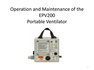
Operation and Maintenance of the EPV200 Portable Ventilator
1
Applications of the EPV200 • The EPV200 Portable Ventilator is a gas powered electronically controlled mechanical ventilator, designed to provide emergency respiratory support by means of a face mask or an endotracheal tube inserted into a patient’s airway. • The EPV200 is a volume controlled ventilator that delivers timecycled constant flow breaths with assist-control function for spontaneous breathing. • The EPV200 is an all-weather ventilator suitable for use at the scene of a medical incident, as well as in pre-hospital, intra-hospital, and inter-hospital transport. • The EPV200 has been designed to withstand direct exposure to rain, up to 100G shock and vibration, and drops of up to 4 feet. • The EPV200 ventilator is intended for use on patients weighing greater than 20kg, or 44 lbs.
2
Overview of Controls and Settings
3
Notes on Controls and Settings • The EPV200 is powered by compressed gas but requires 2D cell batteries to power the controls and settings. This means that the EPV200 requires both batteries and a compressed oxygen source to run. • It features electronic power management alarms to provide advance notice of low gas and low battery status via LED/audible alarms. • The EPV200 has independent control of Tidal Volume, Inspiratory Time, and Breaths Per Minute. • It features electronic ventilation alarms to provide notice of dangerous or ineffective ventilation. • The EPV200 offers an Assist Control function, which will respond to a spontaneous breath by delivering the selected tidal volume of oxygen. It will also reset the breath timing to avoid breath stacking. • The unit also features a digital manometer to monitor the peak airway pressure delivered during each breath. On-board Digital Manometer
4
Overview of Specifications
5
EPV200 Connections
6
Ventilator Connections Oxygen Connection
• •
•
•
•
The EPV 200 must be connected to a 40-80 psi compressed oxygen source to operate. A single use disposable oxygen hose is supplied with this ventilator. Replacement disposable hoses may be purchased or the ventilator can be connected to the gas source with a reusable oxygen hose. The oxygen can be supplied via an oxygen tank using any oxygen pressure regulator with a DISS outlet. Alternatively, the ventilator can be run from a wall oxygen source by fitting the oxygen hose with the appropriate adaptor for the oxygen outlet style used in the facility. Connect a compressed oxygen source by attaching one end of an oxygen hose to the DISS oxygen inlet shown above, and then connecting the other end to an oxygen regulator, or hospital or ambulance oxygen outlet. Ensure that the oxygen source is pressurized and capable of delivering oxygen at 4080 psi. 7
Ventilator Connections Patient Circuit Connection
• To attach the breathing circuit, press the open end of a three-foot circuit with one-way valve firmly on to the 22 mm patient circuit connection. • The circuit connection will accommodate any standard 22 mm ventilation circuit with a one-way valve, although the EPV200 has been tested and approved using the Allied three-foot breathing circuits with one-way valve.
8
Ventilator Connections Patient Circuits • •
• •
Allied offers several affordable circuit configurations to meet the caregiver’s requirements. All circuits contain three feet of corrugated tubing, a one-way duck-bill valve, an expiratory port capable of accepting a PEEP valve or bacterial filter, and a swivel connector capable of accepting a mask or ET tube. Optional configurations incorporate a pre-packaged cuffed mask and/or a bacterial exhalation filter. The following part numbers represent the various pre-packaged configurations and accessory items offered for the EPV200. Ventilator Circuit Configurations for EPV200 Portable Ventilator Allied Part # L599-140* 3 foot circuit, One Way Valve, Swivel Connector, Adult cuffed Mask, Exhalation Filter L599-190** 3 foot circuit, One Way Valve, Swivel Connector, Exhalation Filter (No Mask) L599-130* 3 foot circuit, One Way Valve, Swivel Connector, Adult cuffed Mask (No Filter) L599-180** 3 foot circuit, One Way Valve, Swivel Connector (No Mask or Filter)
Case Quantity 10 10 10 10
* circuit configuration designed for use on non-intubated or intubated patients. Mask can be removed to attach to ET tube. ** circuit configuration designed for use on intubated patients. Circuit attaches to ET tube directly.
Circuit Accessories Available From Aliied Healthcare Products, Inc. Allied Part # LPEEP† Adjustable PEEP Valve, 0-20cm H2O L599-200 L595161-10 L595162-10
Bacterial Exhalation filter Adult Oxygen Mask Child Oxygen Mask
† PEEP valve includes 30mm-18mm adaptor to fit allied 18mm circuit exhalation port
Case Quantity 12 10 10 10
9
Patient Circuit Connections Stand alone accessories for patient circuits
10
Patient Circuit Connections Fitting of PEEP Valve and Mask or ET Tube • An External PEEP valve may be fitted to the expiratory port of the patient circuit, allowing adjustable PEEP from 0-20 cm H2O. • The swivel connector on the three-foot Allied patient circuit features a 22 mm O.D.,15mm I.D. universal adapter that will accept a standard cuffed mask or endotracheal tube. • To fit the mask or ET tube, press the open end of the swivel connector on the end of the circuit into the mask or tube inlet opening. • The patient circuit also contains a removable access port. Ensure that this port is closed during ventilation to prevent loss of airway pressure.
11
Patient Circuit Connections Overview of Allied Patient Circuit Connections
12
Battery Installation Battery Compartment Thumb Screws
• • • • •
For the EPV200 to function, two D cell batteries must be installed in the battery compartment. Two D cell batteries are supplied with the unit. The batteries will provide 48 hours of run time under ventilation parameters of 10 BPM and 2-second Inspiratory Time, and 640 ml Tidal Volume. To install the batteries, loosen the four brass thumb screws on the battery compartment cover. Remove the cover and install the batteries as indicated with the positive terminals facing toward the top of the unit as shown. Replace the cover with the operating instructions facing up, and tighten the thumb screws to create a positive seal of the rubber gasket.
13
Start-Up Powering On the Unit
• Ensure that a 40-80 psi gas source is attached and pressurized, and the batteries are installed. • Ensure that a patient circuit is installed (to prevent patient disconnect alarm from activating, the circuit output should be attached to a test lung or device that provides similar compliance to human lungs). • Press the power button to power on the unit. • The unit will go through a start-up mode in which all the LEDs and lights will flash, and then the unit will begin to operate according to the set parameters. 14
EPV200 Controls and Settings
15
Controls and Settings Inspiratory Time Adjustment Press to select 1 second (child) I Time Press to select 2 second (adult) I Time
• The Inspiratory Time is selectable at 1 second or 2 seconds, and color coded for ventilation of Child (Orange) or Adult (Black) patients. • To change the Inspiratory Time setting, press the desired 1 SEC or 2 SEC button on the keypad. • A green LED will indicate the selected inspiratory time 16
Controls and Settings Breaths Per Minute Adjustment
Press to increase BPM Press to decrease BPM
• •
Can be set at 0 or 8-20 Breaths Per Minute when inspiratory time is set to 2 Sec. Can be set at 0 or 8-30 Breaths Per Minute when inspiratory time is set to 1 Sec. –
• •
The 0 BPM setting allows the ventilator to function solely in Assist mode, and will only deliver the set tidal volume when a breath is initiated by the patient. If using this mode, ensure that the tidal volume knob is set to a accommodate the necessary tidal volume required by the patient.
To change the Breaths Per Minute Setting, press the up or down arrows on the keypad near the BPM label. The digital readout will display the setting. Recommended AHA guidelines for ventilation: – –
Adult: 8-12 BPM Child: 12-20 BPM
17
Controls and Settings Tidal Volume Adjustment Selection Indicator Arrow
• • •
•
The Tidal Volume is adjustable from 200-1200 ml and is color keyed for 1 Second or 2 Second ventilation If your inspiratory time is set to 2 seconds (Adult), refer to the Black numerical markings and select the most appropriate tidal volume from the choices on the dial. If the inspiratory time is set to 1 second (Child), refer to the Orange numerical markings and select the most appropriate tidal volume from the choices on the dial. The following is a table of approximate settings for tidal volume by patient height, derived from ideal body weight with oxygen delivery at 10ml/Kg. This table is an approximation for reference only. Refer to direction of a physician or medical professional for appropriate settings. 6' 5 " 6' 8" 880
6' 8" 6' 11" 7' 3" 7' 6" 6' 10" 960 1040 1120 1200
Height Adult Male (in feet' and Inches") Height Adult Female (in feet' and Inches") Approximate Tidal Volume Setting
4' 8" 4' 11" 5' 3" 5' 6" 5' 10" 6' 1" 4' 10" 5' 1" 5' 5" 5' 8" 6' 0" 6' 5" 400 480 560 640 720 800
Height Child Male (in feet' and Inches") Height Child Female (in feet' and Inches") Approximate Tidal Volume Setting
3' 11" 4' 1" 4' 2" 4' 4" 4' 6" 4' 8" 4' 9" 4' 11" 5' 1" 4' 1" 4' 3" 4' 4" 4' 6" 4' 8" 4' 10" 4' 11" 5' 1" 5' 3" 200 240 280 320 360 400 440 480 520
18
Safety Alarms •
The EPV200 features the following alarms: – – – –
• •
• •
High airway pressure Low airway pressure Low battery (visual alarm only) Low Source Gas
All alarms on the EPV200 are pre-set and non-adjustable. Alarms are signaled both audibly and visibly except for the low battery alarm, which provides only a visible alarm signal to conserve battery power. When an alarm is activated a 60 Db audible alarm will sound, and the appropriate red alarm LED will illuminate, signaling the type of alarm activated. Audible alarms can be silenced for 110 seconds by pressing and holding the selected inspiratory time button for 3 seconds (the one that has a green LED).
Low battery if illuminated (visual alarm only) Low source gas pressure if illuminated High airway pressure if illuminated Low airway pressure if flashing
60 Db Alarm Tone
Flashing Alarm Status LEDs 19
Safety Alarms Alarm Details •
High Airway Pressure Alarm (audible/visual): – – – –
–
Activates at 45 cm H2O, indicating that the patient airway is obstructed or lungs have becoming non-compliant. Check the connections and airway. Will sound a consistent tone and the High Airway Pressure LED will illuminate Note that the EPV200 features a safety pressure relief that will limit airway pressures to less than 60 cm H2O, to prevent damage to the lungs. This alarm is automatically cleared when 25 seconds pass without a high airway pressure being detected. This alarm can be silenced for 110 seconds by pressing and holding the selected inspiratory time button for 3 seconds (the one that has a green LED).
High airway pressure if illuminated
20