Service Manual
44 Pages
Preview
Page 1
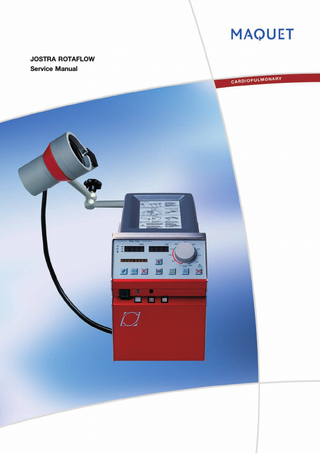
JOSTRA ROTAFLOW Service Manual
Contents
JOSTRA ROTAFLOW
Contents 1
2
3
4
5
6
Important ... 4 1.1
Purpose... 4
1.2
Service ... 4
1.3
Special Notes... 6
1.4
Manuals ... 6
1.5
Location of Signs and Labels ... 7
Introduction... 8 2.1
General ... 8
2.2
System components ... 9
2.3
ROTAFLOW Console RFC... 10
2.4
ROTAFLOW Drive Unit RFD ... 11
2.5
ROTAFLOW Emergency Drive RFE ... 11
Description of functions ... 12 3.1
ROTAFLOW Console flow measuring board RFC_FM... 12
3.2
ROTAFLOW Console control board RFC_CO ... 14
3.3
ROTAFLOW Console power supply board RFC_PS ... 16
3.4
ROTAFLOW RS232 board RFC_RS... 18
3.5
ROTAFLOW Front panel board RFC_FP... 18
3.6
ROTAFLOW Interconnection board RFC_ICO ... 18
3.7
Setting of mains voltage ... 18
Disassembling and assembling... 19 4.1
ROTAFLOW Console RFC... 20
4.2
ROTAFLOW Drive Unit RFD ... 22
4.3
ROTAFLOW Emergency Drive RFE ... 22
Service procedures ... 23 5.1
Function check... 23
5.2
Service terminal ... 26
Troubleshooting ... 30 6.1
7
8
2
Error messages ... 30
Preventive maintenance ... 33 7.1
Preventive maintenance interval ... 33
7.2
Performing the Preventive maintenence ... 34
7.3
Battery replacement... 36
Installation... 38 8.1
Unpacking ... 38
8.2
Function check after installation ... 38
8.3
Formal handover... 38 Service Manual
Revision 00
JOSTRA ROTAFLOW
9
Contents
Diagrams...41 9.1
ROTAFLOW Console RFC wiring diagram...41
9.2
ROTAFLOW Drive Unit RFD wiring diagram ...42
Revision 00
Service Manual
3
1. Important
JOSTRA ROTAFLOW
1
Important
1.1
Purpose The purpose of this service manual is to describe the JOSTRA Centrifugal Pump System ROTAFLOW in order to give understanding necessary for making checks after installation, adjustments, locating and repairing faults etc.
1.2
Service
1.2.1
General Responsibility for the safe functioning of the equipment reverts to the owner or user in all cases in which service or repair has been done by a non-professional or by persons who are not employed by or authorized by MAQUET, and when the equipment is used for other than its intended purpose. In addition to the Important information given here and in the related documents (e. g. in the User's Manual), always pay attention to applicable local and national regulations. Record all User options and restore them if altered during service. If unit is used on HL 20 then record mode setting before removing unit from console. Refer to Rotaflow User’s Manual, chapter 4. Operation, for a description of available options.
1.2.2
Hazard notices WARNING
Service by unqualified service engineer! Only service engineers trained and authorized by MAQUET shall be permitted to perform installation, service or maintenance of the ROTAFLOW. Service by an unqualified service engineer may result in injury to the technician, the patient, other personnel or may cause damage to the equipment.
WARNING
Disassembling or assembling! Before disassembling or assembling of the ROTAFLOW, make sure that the: – On/Off Switch is set to Off. – Mains power cable is disconnected. – Backup batteries are disconnected. – The unit is cleaned according to instructions in the User's Manual.
4
Service Manual
Revision 00
JOSTRA ROTAFLOW
WARNING
WARNING
CAUTION
1. Important
Energized electrical components! With power supply connected to the ROTAFLOW, there are energized electrical components inside the unit. All personnel must exercise extreme caution if fault tracing or adjustments are performed with power supply connected.
Leakage currents! When the unit is used together with other medical machines the total of the leakage currents must be checked.
ESD sensitive components! When handling ESD-sensitive devices, established procedures must be observed to prevent damage. When working with ESD sensitive components, always use a grounded wristband and a grounded work surface. Adequate service tools must always be used.
1.2.3
Preventive maintenance The ROTAFLOW must be serviced at regular intervals by personnel trained and authorized by MAQUET. Refer to chapter “7 Preventive maintenance”. Any maintenance or service must be noted in a logbook provided.
1.2.4
Functional check After any installation, maintenance or service intervention in the ROTAFLOW, perform a Function check according to instructions in chapter “5 Service procedures”.
1.2.5
To the responsible service personnel The contents of this document are not binding. If any significant difference is found between the product and this document, please contact MAQUET for further information. We reserve the right to modify products without amending this document or advising the user. Only personnel trained and authorized by MAQUET shall be permitted to perform installation, service or maintenance of the ROTAFLOW. Only MAQUET genuine spare parts must be used. PC boards (spare parts) must always be kept in a package for sensitive electronic devices. MAQUET will not otherwise assume responsibility for the materials used, the work performed or any possible consequences of same. Components on PC boards must not be replaced. The PC board is the only available spare part. The information in this manual regarding components on the PC boards is intended for troubleshooting only.
Revision 00
Service Manual
5
1. Important
JOSTRA ROTAFLOW
Many circuit boards have jumpers which require proper placement for correct operation. Verify that jumper settings on new boards are identical with the boards being replaced. If installing a newer revision board then contact MAQUET Technical Support for assistance. Special waste. This product contains electronic and electrical components. Discard disposable, replaced and left-over parts in accordance with appropriate industrial and environmental standards.
1.3
Special Notes Pay attention to the special notes in the manual.
WARNING
CAUTION
Danger of severe personal injury! An instruction or procedure, which if not carried out correctly, may result in injury to the technician, the patient or other personnel.
Danger of damage to the equipment! An instruction or procedure, which if not carried out correctly, may damage the equipment.
NOTE Notes are used to provide important or explanatory information.
1.4
Manuals Service documentation for the ROTAFLOW consists of:
6
Manual
Contents
User’s Manual
Practical and functional description of the ROTAFLOW. The User’s Manual is an indispensable complement to the Service Manual for proper servicing.
Service Manual
This Manual.
Spare Parts information
Spare Parts information is published in the ROTAFLOW Spare Parts List.
Service Manual
Revision 00
JOSTRA ROTAFLOW
1.5
1. Important
Location of Signs and Labels Symbols are explained in the User’s Manual.
CLS
RFD Master RFS
1
0 RS 232
This is the S/N label for the complete ROTAFLOW unit. The S/N label on the bottom cover plate refers to a sub-unit.
Mains
ROTAFLOW Rear Side
Revision 00
Service Manual
7
2. Introduction
JOSTRA ROTAFLOW
2
Introduction
2.1
General The ROTAFLOW is a centrifugal pump system intended to be used in an extracorporal perfusion circuit to pump blood during cardiopulmonary bypass procedures. It can be used as a fully independent stand-alone unit or as a part of the Heart-Lung Machine console JOSTRA HL 20. Some features of the ROTAFLOW System: • The flow can be kept constant, independent of the pressure. • Air bubbles in the circuit can be detected and prevented from entering the patient. • A too low liquid (blood) level in a reservoir can be detected and regulated (optional). • The system can run on the battery backup. • A more physiologically optimized pulsatile pumping is possible, internally triggered or controlled by the patient’s own ECG. • The pressure can be monitored and regulated when used with an HL 20. • Most functions needed during an operation can be controlled from the system control panel. Useful signals and data are displayed. • A complete perfusion protocol can be recorded on-line or off-line with JOCAP XL for later analysis and printout.
8
Service Manual
Revision 00
JOSTRA ROTAFLOW
2.2
2. Introduction
System components
ROTAFLOW Console RFC
ROTAFLOW Drive Unit RFD
The RFC is the systems control module with triple power supply; mains, internal back-up battery or HL 20 if connected.
The RFD is the drive unit for the Centrifugal Pump. This unit also incorporates flow sensor and bubble detection. The hydraulic swivel-joint bracket assures ideal positioning of the RFD.
ROTAFLOW Emergency Drive RFE
ROTAFLOW Centrifugal Pump RF
The RFE is an emergency drive for the Centrifugal Pump.
The RF is the disposable pump head intended for the RFD and RFE.
When operated, LEDs (speed indicators) shows RPM.
Due to the combination of mechanical and magnetic bearing, the mechanical friction potential clotting zones are significantly reduced. The centrifugal pump’s minimal priming volume of 32 ml considerably reduces hemodilution.
Revision 00
Service Manual
9
2. Introduction
2.3
JOSTRA ROTAFLOW
ROTAFLOW Console RFC 7
1
8
2
9
3 CLS
4
10
RFD Master RFS
1
0
5
RS 232
12
Mains
1
2
3
4
6
Front view
11
Rear view
1. On/Off switch.
1. Battery pack cover.
2. External voltage LED. Lit when an external voltage is available.
2. Level sensor socket (“CLS”).
3. Battery operation LED. Lit during internal battery operation. 4. Battery charging LED. Lit when the batteries are being charged.
3. Socket for master ROTAFLOW Drive Unit (“RFD Master”). 4. Not used. 5. Mains circuit-breaker. 6. Mains socket. 7. ROTAFLOW Drive Unit holder. 8. Label. 9. Plastic cover. 10. RS232 socket. 11. Connection for potential equalization. 12. Cover for RS232 socket.
10
Service Manual
Revision 00
JOSTRA ROTAFLOW
2.4
2. Introduction
ROTAFLOW Drive Unit RFD 4 5 6 7
1. Holder. 2. Ventilation slot collar. 3. Cable. 4. Position for ROTAFLOW Centrifugal Pump. 5. Lock. 6. Flow meter and bubble sensor. 7. Hydraulic bolt for all arm joints.
1
2.5
2
3
ROTAFLOW Emergency Drive RFE 1. Position for ROTAFLOW Centrifugal Pump. 2. Speed LEDs. Show 1500 RPM to 5000 RPM in steps of 500 RPM (above 5000 RPM, all LEDs are lit). 3. Hand crank.
1
2
3
4
5
4. Butterfly screw. Attach to a Heart Lung Machine or to the ROTAFLOW Drive Unit holder on the ROTAFLOW Console. 5. Holders.
Revision 00
Service Manual
11
3. Description of functions
JOSTRA ROTAFLOW
3
Description of functions
3.1
ROTAFLOW Console flow measuring board RFC_FM RFC_FM receives the flow and bubble signals directly from the Drive Unit via the coax cable. Inputs and outputs are shown in the Wiring Diagram.
RFC_FM board
12
Service Manual
Revision 00
JOSTRA ROTAFLOW
3. Description of functions
Jumper settings Verify that jumper settings on new boards are identical with the boards being replaced. If installing a newer revision board then contact MAQUET Technical Support for assistance. Test points
Revision 00
Test point
Name
Description
TP0
0 VL
Logik GND (to be used when measuring +5 V)
TP1
0 VS
Analog GND (to be used when measuring +12 V and -12 V)
TP2
+5 V
+5 V Power Supply for digital circuit
TP3
+12 V
+12 V Positive Power Supply for analog circuit
TP4
-12 V
-12 V Negative Power Supply for analog circuit
TP5
+5 VA
+5 VA Positive Power Supply for analog circuit
TP6
VREF
+5.0 V reference voltage
TP10
–
+1.908 V reference voltage
TP11
–
+0.592 V reference voltage
Service Manual
13
3. Description of functions
3.2
JOSTRA ROTAFLOW
ROTAFLOW Console control board RFC_CO RFC_CO is the Control board collecting all data. Includes also the safety system. Connector P5 is used for the Service terminal cable (to access the Service terminal). The Service terminal can also be connected to the Front panel board RFC_FP. Software is stored in the replaceable FLASH EPROM at socket IC8. Inputs and outputs are shown in the Wiring Diagram.
RFC_CO board On newer units, the Buzzer BZ1 is replaced by a connector to which an external buzzer is connected. 14
Service Manual
Revision 00
JOSTRA ROTAFLOW
3. Description of functions
Jumper settings Verify that jumper settings on new boards are identical with the boards being replaced. If installing a newer revision board then contact MAQUET Technical Support for assistance. Test points Test point
Name
Description
TP1
0 VS
Analog GND (to be used when measuring +12 V and -12 V)
TP2
CLS_SIG
Input signal of CLS
TP3
0 VL
Logik GND (to be used when measuring +5 V)
TP4
+5 V
+5 V Power Supply for digital circuit
TP5
+12 V
+12 V Positive Power Supply for analog circuit
TP6
CLS_CUR
Current consumption of CLS, 1 mA = 0.313 V
TP7
-12 V
-12 V Negative Power Supply for analog circuit
TP8
CLS_VCC
+9 V Power Supply for CLS20-535
TP9
UREF1
+5.000 V reference voltage
TP10
VAREF
+5.000 V reference voltage for 80C517
Connectors Connectors are shown in the Wiring Diagram, but the information regarding connectors is not complete. Refer to table below. Conn. # P2
Name
Pin #
Front Panel 34p. Flatcable to Display board
P3
Slave ext. Not used.
P4
Slave int. Not used.
Revision 00
Description
1 2 3 4
0VL 0VL +5V +5V
1 2 3 4
SPEED_DIFF_IP SLAVE_VAL 0VS Not connected
1 2 3 4
UREF1 SET_SLAVE_INT 0VS Not connected
P5
Service Terminal
1 2 3 4
RxD TxD NOSERVICE 0VL
P6
Flow
1 2 3 4 5 6
UREF1 SET_VAL_P1 0VS UREF1 Setvalue RFD 0VS
Service Manual
15
3. Description of functions
3.3
JOSTRA ROTAFLOW
ROTAFLOW Console power supply board RFC_PS RFC_PS handles power supply in the unit. The battery charger function is also included on this board. Inputs and outputs are shown in the Wiring Diagram.
RFC_PS board
16
Service Manual
Revision 00
JOSTRA ROTAFLOW
3. Description of functions
Jumper settings Verify that jumper settings on new boards are identical with the boards being replaced. If installing a newer revision board then contact MAQUET Technical Support for assistance. Test points Test point
Name
Description
TP0
0 VL
Logik GND (to be used when measuring +5 V)
TP1
0 VS
Analog GND (to be used when measuring +12 V and -12 V)
TP2
+5 V
+5 V Power Supply for digital circuit
TP3
+12 V
+12 V Positive Power Supply for analog circuit
TP4
-12 V
-12 V Negative Power Supply for analog circuit
TP5
I_BATT_SIGN
0 V = Battery charging +5 V = Battery discharging
TP6
–
Battery charge voltage, 30 V – 34 V
TP7
+24 V Line
+24 V Power Supply from Mains TrafoRectifier circuit
TP8
+24 V HL20
+24 V Con Power Supply from HL 20
TP9
+24 V
+24 V Power Supply RFD
TP11
U_BATT
Battery voltage: 19 V = 0.126 V 32 V = 3.29 V
TP12
I_BATT
Battery current: 5 A = 2.5 V
TP13
U_LINE
Power Supply from Mains Trafo-Rectifier circuit: 19 V = 0.126 V 32 V = 3.29 V
Revision 00
Service Manual
17
3. Description of functions
3.4
JOSTRA ROTAFLOW
ROTAFLOW RS232 board RFC_RS RFC_RS provides rear panel RS232 level conversion (JOCAP). There are no jumper settings or test points on this board. Inputs and outputs are shown in the Wiring Diagram.
3.5
ROTAFLOW Front panel board RFC_FP RFC_FP contains all display and interface circuitry for user adjustments. A connector on the Front panel board RFC_FP can be used for the Service terminal. There are no jumper settings or test points on this board. Inputs and outputs are shown in the Wiring Diagram.
3.6
ROTAFLOW Interconnection board RFC_ICO RFC_ICO is the interconnection board for the Console electronics. There are no jumper settings or test points on this board. Inputs and outputs are shown in the Wiring Diagram.
3.7
Setting of mains voltage To select mains voltage, connect the power supply leads at the screw terminals of the transformer. Refer to the Wiring Diagram. Mount a mains circuit-breaker of 1 A for 230–240 V and 2 A for 100–115 V. Mount the labeling and mark the selected mains voltage.
18
Service Manual
Revision 00
JOSTRA ROTAFLOW
4
4. Disassembling and assembling
Disassembling and assembling WARNING
Disassembling or assembling! Before disassembling or assembling of the ROTAFLOW, make sure that the: – On/Off Switch is set to Off. – Mains power cable is disconnected. – Backup batteries are disconnected. – The unit is cleaned according to instructions in the User's Manual.
WARNING
CAUTION
Energized electrical components! With power supply connected to the ROTAFLOW, there are energized electrical components inside the unit. All personnel must exercise extreme caution if fault tracing or adjustments are performed with power supply connected.
ESD sensitive components! When handling ESD-sensitive devices, established procedures must be observed to prevent damage. When working with ESD sensitive components, always use a grounded wristband and a grounded work surface. Adequate service tools must always be used.
Revision 00
Service Manual
19
4. Disassembling and assembling
4.1
JOSTRA ROTAFLOW
ROTAFLOW Console RFC Bottom cover plate Remove the six screws pointed out in the illustration and lift up the cover plate on the underside of the unit. The spring loaded ODU plug cover is secured in open position by the latch. When the console is placed on a flat surface, the latch releases the cover. Adjust if required.
To remove the bottom cover plate, all cables connected to the cover plate must be disconnected.
The RFS_RS board, accessible with the bottom cover plate removed, is not visable in this illustration.
Front panel Remove the eight screws (four on each side) and lift off the front panel.
20
Service Manual
Revision 00