Anspach
Anspach Electric High Power Drilling and Cutting Systems
The eMax 2 and eMax 2 plus Instructions for Use Dec 2011
Instructions for Use
44 Pages
Preview
Page 1
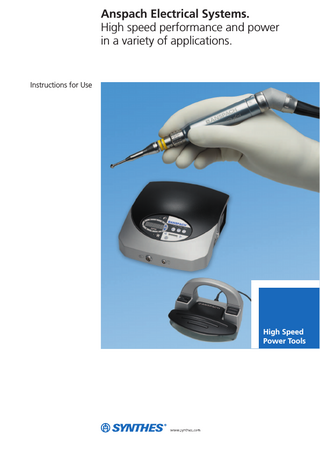
Anspach Electrical Systems. High speed performance and power in a variety of applications.
Instructions for Use
High Speed Power Tools
Table of Contents
Introduction
Operating Instructions
Attachments and Dissection Tool Assembly
Synthes Anspach
2
Electric High Performance Instrument Systems
2
Indications
3
Warnings and Cautions
4
Technical Specifications
5
Glossary of Symbols
10
eMax 2 and eMax 2 Plus
11
e12 Small Bone System
19
Straight Attachments and Cutting Burr Assembly
20
Minimal Access Attachments and Dissection Tool Assembly 26
Care and Maintenance
Micro Curved Attachment
28
MicroSaws and Small Attachments Assembly
29
Sagittal Saws
32
Compact SpeedReducer
33
Cleaning and Maintenance
34
Sterilization
36
Troubleshooting
37
Ordering Information
38
Warranty and Return Policies
39
Anspach Electrical Systems
Instructions for Use
Synthes
1
Anspach Electrical Systems. High speed performance and power in a variety of applications.
Synthes Anspach Synthes Anspach manufactures pneumatic and electric high performance instruments and attachments to meet the specific needs of both surgeon and staff. While the advanced design of these instruments provides unparalleled performance and reliability, they also allow for effortless assembly, meeting the needs of both surgeon and staff for the most demanding applications. No tools are required to assemble dissection tools or attachments. All Synthes Anspach instruments are manufactured to conform to rigorous quality standards to provide dependable performance. Important: Before using any of the Synthes Anspach High Performance Systems, it is imperative that all individuals working with the system read this operating manual. The surgeon is responsible for learning the proper techniques in the use of this system, as improper use may cause injury.
To schedule a hands-on training course, please contact your local Synthes sales representative. If you have any questions after reading this manual, please call
Electric High Performance Instrument Systems The eMax 2® operates up to 80,000 rpm. It offers variable speed, bi-directional operation, minimal noise levels, and an optional hand control. It is a high performance system that highlights minimal vibration performance, thermal energy management, and high reliability for Neurosurgeons, Neurotologists, Skull Base Surgeons, Spinal Surgeons, and Otolaryngologists. The eMax 2 Plus incorporates all of the features of the eMax 2, but with a higher degree of torque. The additional torque is beneficial for power demanding procedures. The e12 is designed specifically to meet the demands of surgical applications requiring a low speed instrument at a high performance level that is the hallmark of Anspach systems. It combines the advantages of an electric system with an optimum balance of power, smooth operation, and ergonomic comfort. The eMax 2 and eMax 2 Plus System Consoles provide power to the e12 for variable speed operation up to 12,000 rpm with your choice of either foot or hand control. The e12 quick disconnect mechanism provides simple exchange of Synthes Anspach microSaw attachments and small attachments (J-Latch and Jacobs Chuck) resulting in a complete range of attachments and tools for all of your small bone procedures.
your local Synthes sales representative.
eMax 2 plus
2
Synthes
e12
Anspach Electrical Systems
Instructions for Use
Indications
The Anspach High Speed Electric Systems are intended for cutting and shaping bone including spine and cranium. The Anspach High Speed Electric System is comprised of Handpiece models eMax2, eMax2 Plus, E12, & E-Sagittal; Electric Consoles models SC2000, SC2000U, SC2100, SC2101, & SC2102; Foot Control models E-FP, E-FP-DIR, E-FP-DIR/IRR, EPLUS-FP, EPLUS-FP-NS, EMAX2-FP, EMAX2-FP-NS; Hand Controls EMAX2-HC & E12-HC.
Spine surgery
Neurosurgery
ENT surgery
Anspach Electrical Systems
Instructions for Use
Synthes
3
Warnings and Cautions
Surgeon is responsible for learning proper techniques in use of equipment; improper use may cause serious injury to user or patient or damage to system. Instrument operator and all operating room personnel must wear eye protection. Visually inspect for damage before using; do not use if damage is evident. Do not use accessories other than those provided by Synthes Anspach and specified for use with Anspach systems. Use care to protect hose when handling, cleaning, and during system use. Damage to hose can cause leaking, rupture, or other related failures.
Confirm attachment is proper size for dissection tool and that it is secure. Gently pull on dissection tool shaft to ensure it is fully seated and properly installed. Do not engage safety mechanism while handpiece is running; doing so makes safety mechanism inoperable. Only cut visible areas unless an image intensifier is utilized. Delicate structures in proximity to dissection must be thoroughly protected to prevent injury. Irrigation is necessary for proper operation. Maintain firm control of instrument at all times. Do not bend or use as a lever.
Do not step on, set equipment on, pinch, kink, clamp, or otherwise occlude handpiece hose during use.
Use a gentle tapping motion or side-to-side motion and let instrument do cutting.
Do not use if the product sterilization barrier or its packaging is compromised.
Do not use excessive force.
Do not use, or discontinue use of powered equipment exhibiting excessive temperatures that can cause patient injury (necrosis) and/or user discomfort.
Forceful side loading of dissection tool may cause fracture of dissection tool, which may cause injury. Dissection tools are disposable and intended for single patient use only. Do not re-sterilize and/or re-use dissection tools.
Use of damaged or improperly maintained power equipment and/or misused powered equipment can result in excessive temperatures.
Use standard protocol for disposal of sharp instruments.
To insure equipment operates as designed, read and follow manufacturer's instructions, including those for proper service and maintenance.
Do not operate in an explosive flammable environment.
Do not operate handpiece without an attachment and the corresponding dissection tool.
Continuous extreme cutting at or near stalling conditions will quickly overheat handpiece.
Do not modify ground or power cord. Do not allow liquid into console.
Use caution to avoid cutting or tearing gloves while handling dissection tools.
Portable and Mobile RF communications equipment can affect Medical Electrical Equipment.
Dissection tools must be adequately retained within attachment to prevent distal migration, which may cause injury.
Use of accessories or cable other than those provided by Synthes Anspach, and specified for the electric system in use, may result in increased emissions or decreased immunity.
4
Synthes
Anspach Electrical Systems
Instructions for Use
Technical Specifications
eMax 2 and eMax 2 Plus Handpiece Specifications Speed: 10,000 – 80,000 rpm Handpiece/hose 3.81 m (12.5 ft) Outside housing (diameter) 18.8 mm (.74 in) Length of housing 127 mm (5 in) Handpiece weight 104 g (3.7 oz) Handpiece, Hose Weight 0.59 kg (1.29 lbs) Console (SC2000, SC2100, SC2101, SC2102) Specifications Electrical: Primary: 100 –240 VAC, 50 – 60 Hz, 2– 3 A Secondary: 24 VDC @11 A Leakage Current: (<100 μA) Mechanical: Size: 31.115 cm⳯14.6 cm⳯32.7 cm (12.25 in⳯5.74 in⳯12.87 in) Weight: 6.25 kg (13.77 lbs)
Foot Pedal (E-FP, E-FP-DIR, E-FP-DIR/IRR) Specifications Size: 26.7 cm⳯16.5 cm⳯14.7 cm (10.5 in⳯6.5 in⳯8.5 in) Weight: 2.0 kg (4.41 lbs) Cord: 3.66 m (12 ft) in length Patent Information Synthes Anspach products are manufactured under one or more of the following U.S. Patent Nos. RE 37,358; 5,405,348; 5,601,560; 5,630,818; 5,741,084; 5,904,687; 6,607,533; 6,733,218; 6,746,153; 6,749,341; 6,969,368; 7,128,544; 7,144,415; 7,217,090; 7,255,546; 7,261,526 and 7,458,979. Additional U.S. and International patents pending.
Additional Information All specifications are subject to change.
The device complies with the following standards: IEC 60601-1 / IEC 60601-1-2 IEC61000-3-2 / IEC61000-3-3 / IEC61000-4/2 / IEC61000-4-4 / IEC 61000-4-5 / IEC 61000-4-11 / IEC 61000-4-8 / IEC 61000-4-6 / IEC 61000-4-3
With regard to electrical shock, fire, mechanical hazards this device is certified to UL 60601-1 and CAN/CSA C22.2 No. 601.1 This device complies with applicable EEC directives.
Anspach Electrical Systems
Instructions for Use
Synthes
5
Technical Specifications
Table 1: Emission The Synthes Anspach High Speed Electric System is comprised of handpiece models eMax2, eMax2 Plus, E12, & E-Sagittal; Electric Consoles models SC2000, SC2000U, SC2100, SC2101, & SC2102; Foot Control models E-FP, E-FP-DIR, E-FP-DIR/IRR, EPLUS-FP, EPLUS-FP-NS, EMAX2-FP, EMAX2-FP-NS; Hand Controls EMAX2-HC & E12-HC. Guidance and manufacturer’s declaration – electromagnetic emissions The Synthes Anspach High Speed Electric System is intended for use in the electromagnetic environment specified below. The customer or the user of the Synthes Anspach High Speed Electric System should assure that it is used in such an environment. Emission test
Compliance
Electromagnetic environment – guidance
RF emissions CISPR 11
Group 1
The Synthes Anspach High Speed Electric System uses RF energy only for its internal function. Therefore, its RF emissions are very low and are not likely to cause any interference in nearby electronic equipment.
RF emissions CISPR 11
Class A
Harmonic emissions IEC 61000-3-2
Class A
The Synthes Anspach High Speed Electric System is suitable for use in all establishments, other than domestic establishments and those directly connected to the public low-voltage power supply network that supplies buildings used for domestic purposes.
Voltage fluctuations / flicker emissions IEC 61000-3-3
Complies
6
Synthes
Anspach Electrical Systems
Instructions for Use
Table 2: Immunity (all devices) Guidance and manufacturer’s declaration – electromagnetic immunity The Synthes Anspach High Speed Electric System is intended for use in the electromagnetic environment specified below. The customer or the user of Synthes Anspach High Speed Electric System should assure that it is used in such an environment. Immunity test standard
IEC 60601 test level
Compliance level
Electromagnetic environment – guidance
Electrostatic discharge (ESD) IEC 61000-4-2
±6 kV contact
±6 kV contact
±8 kV air
±8 kV air
Floors should be wood, concrete or ceramic tile. If floors are covered with synthetic material, the relative humidity should be at least 30%
Electrical fast transient / burst IEC 61000-4-4
±2 kV for power supply lines ±1 kV for input/output lines
±2 kV for power supply lines ±1 kV for input/output lines
Mains power quality should be that of a typical commercial or hospital environment.
Surge IEC 61000-4-5
±1 kV line to line ±2 kV line to earth
±1 kV line to line ±2 kV line to earth
Mains power quality should be that of a typical commercial or hospital environment.
Voltage dips, short interruptions and voltage variations on power supply lines IEC 61000-4-11
<5% UT (0.5 cycle)
<5% UT (0.5 cycle)
40% UT (5 cycles)
40% UT (5 cycles)
Mains power quality should be that of a typical commercial or hospital environment.
70% UT (25 cycles)
70% UT (25 cycles)
<5% UT for 5s
<5% UT for 5s
Note: UT is the a.c. mains voltage prior to application of the test level. Power frequency (50/60 Hz) magnetic field IEC 61000-4-8
3 A/m
3 A/m
Power frequency magnetic fields should be at levels characteristic of a typical location in a typical commercial or hospital environment.
Anspach Electrical Systems
Instructions for Use
Synthes
7
Technical Specifications
Table 3: Immunity (not life-supporting devices) Guidance and manufacturer’s declaration – electromagnetic immunity The Synthes Anspach High Speed Electric System is intended for use in the electromagnetic environment specified below. The customer or the user of the Synthes Anspach High Speed Electric System should assure that it is used in such an environment. Immunity test standard
IEC 60601 test level
Compliance level
Electromagnetic environment – guidance
Conducted RF IEC 61000-4-6
3 Vrms 150 kHz to 80 MHz
3V
Radiated RF IEC 61000-4-3
3 V/m 80 MHz to 2.5 GHz
3 V/m
Portable and mobile RF communications equipment should be used no closer to any part of the Synthes Anspach High Speed Electric System, including cables, than the recommended separation distance calculated from the equation applicable to the frequency of the transmitter. Recommended separation distance d = 1.2 √P d = 1.2 √P
80 MHz to 800 MHz
d = 2.3 √P
800 MHz to 2.7 GHz
Where P is the maximum output power rating of the transmitter in watts (W) according to the transmitter manufacturer and d is the recommended separation distance in metres (m). Field strengths from fixed RF transmitters, as determined by an electromagnetic site survey,a should be less than the compliance level in each frequency range.b Interference may occur in the vicinity of equipment marked with the following symbol: Note 1: At 80 MHz and 800 MHz, the higher frequency range applies. Note 2: These guidelines may not apply in all situations. Electromagnetic propagation is affected by absorption and reflection from structures, objects and people. a
Field strengths from fixed transmitters, such as base stations for radio (cellular/cordless) telephones and land mobile radios, amateur radio, AM and FM radio broadcast and TV broadcast cannot be predicted theoretically with accuracy. To assess the electromagnetic environment due to fixed RF transmitters, an electromagnetic site survey should be considered. If the measured field strength in the location in which the Synthes Anspach High Speed Electric System is used exceeds the applicable RF compliance level above, the Synthes Anspach High Speed Electric System or the device which contains it should be observed to verify normal operation. If abnormal performance is observed, additional measures may be necessary, such as reorienting or relocating the device containing the Synthes Anspach High Speed Electric System. b Over the frequency range 150 kHz to 80 MHz, field strengths should be less than 3 V/m.
8
Synthes
Anspach Electrical Systems
Instructions for Use
Table 4: Recommended separation distances (not life-supporting devices) Recommended separation distances between portable and mobile RF communications equipment and the Synthes Anspach High Speed Electric System The Synthes Anspach High Speed Electric System is intended for use in the electromagnetic environment in which radiated RF disturbances are controlled. The customer or the user of the Synthes Anspach High Speed Electric System can help prevent electromagnetic interference by maintaining a minimum distance between portable and mobile RF communications equipment (transmitters) and the Synthes Anspach High Speed Electric System as recommended below, according to the maximum output power of the communication equipment. Rated maximum output power of transmitter
Separation distance according to frequency of transmitter 150 kHz to 80 MHz
80 MHz to 800 MHz
800 MHz to 2.5 GHz
W
d = 1.2 √P
d = 1.2 √P
d = 2.3 √P
0.01
12 cm
12 cm
23 cm
0.1
38 cm
38 cm
73 cm
1
1.2 m
1.2 m
2.3 m
10
3.8 m
3.8 m
7.3 m
100
12 m
12 m
23 m
For transmitters rated at a maximum output power not listed above, the recommended separation distance d in metres (m) can be estimated using the equation applicable to the frequency of the transmitter, where P is the maximum output power rating of the transmitter in watts (W) according to the transmitter manufacturer. Note 1: At 80 MHz and 800 MHz, the separation distance for the higher frequency range applies. Note 2: These guidelines may not apply in all situations. Electromagnetic propagation is affected by absorption and reflection from structures, objects and people. Note 3: An additional factor of 10/3 is used in calculating the recommended separation distance to decrease the likelihood that mobile/portable communications equipment could cause interference if it is inadvertently brought into patient areas.
Anspach Electrical Systems
Instructions for Use
Synthes
9
Glossary of Symbols
Reference Number (A.K.A. Item Number, Catalog Number, Part Number)
CE Mark (A.K.A. CE Mark [notified body number], Conformité Européene) Meaning: Device complies with applicable EEC Directives
Lot (A.K.A. Lot Number, Batch Number, Batch Code
MR Conditional. No known hazards at 1.5T. 1.5T
Serial Number
Lock (Run) 00/0000
Use By Date (A.K.A. Expiration Date, Expiry) Unlock (Load) Manufacturer Transmitter Interference may occur in the vicinity of equipment marked with this symbol.
Authorized European Representative Sterile R (A.K.A. Sterilized Using Irradiation)
Type B Electrical Equipment Single Use Only (A.K.A. Do Not Reuse) Attention (A.K.A. Caution, Warning, Danger, Important, Note, Refer to Accompanying Documentation)
Instrument System Key
EM eMax 2 and eMax 2 Plus E12 e12
Keep Dry (A.K.A. Protect from Moisture) Sterile unless damaged or open United States Federal law restricts this device to sale by or on the order of a physician or other licensed health-care provider.
10
Synthes
Anspach Electrical Systems
Instructions for Use
Latex-free Certification There is no latex material in Synthes Anspach products or packaging.
eMax 2 and eMax 2 Plus Operating Instructions
The system console houses the electrical components that provide power, control, and cooling functions to the eMax 2 and eMax 2 Plus handpieces. It provides the user control for all system functions via an integral touch pad face panel. The system console has connections for the eMax 2 and eMax 2 Plus handpieces, foot controls, AC power inlet (100/240v) and the main power switch. The eMax 2 and eMax 2 Plus High Speed Handpieces operate up to 80,000 rpm.
Face Panel
Power Switch
Handpiece Connector Port
Foot Control Connector Port
Features and Compatibility
SC2100
SC2101
SC2102
• • • • • • •
• • • • • • •
• • • • • • •
• • • • • • •
E-SAGITTAL**
•
•
•
•
•
EPLUS-FP-NS
•
•
•
•
•
EMAX2PLUS
•
•
•
•
• • • •
E12-HC
SC2000U
• • • • • • •
Hand Controls
EMAX2-HC
SC2000 Foot Controls Accessories Handpieces Console Features
E-FP E-FP-DIR E-FP-DIR-DIR EMAX2-FP EPLUS-FP EMAX2-FP-NS EPLUS-FP-NS
Active Direction Control Switch Active Irrigation Control Switch
Foot Control Features
Consoles
Back of System Console
IV Pole Mount
Power Switch
AC Power Inlet
• • • Swivel (270°)
Attachment Connection Knurled Knob
• Protective Cap
• Handpiece Housing
EMAX2
•
•
•
Two Foot Control Ports*
•
•
•
Two Handpiece Ports*
•
•
•
Console Irrigation
•
•
•
•
•
•
Handpiece Hose
Handpiece Hose Connector •
*If two foot controls or two handpieces are connected upon startup of console it will default to Foot Control 1 and/or Handpiece 1. **Port LED on console face panel does not illuminate when this accessory is connected to console.
Note: The hose length shown above is shorter than the actual length for easier viewing. Hose length is approximately 12 feet.
Anspach Electrical Systems
Instructions for Use
Synthes
11
eMax 2 and eMax 2 Plus Operating Instructions
System Assembly 1. Plug the hospital grade AC power cord into the AC power inlet on the back of the console. Plug the opposite end of the power cord into a standard, Hospital Grade grounded wall outlet. 2. Insert foot control cord connector into Foot Control 1 connector port. (A second foot control cord may be connected into Foot Control 2 connector port on applicable consoles.) Foot control cord connector is keyed. Align foot control cord connector with port on front of console. Do not push foot control cord connector into console connector port when out of alignment. 3. Plug handpiece hose connector into Handpiece 1 connector port located on front of console. (A second handpiece could be connected into Handpiece 2 connector port on applicable consoles.) Handpiece hose connector is keyed. Align handpiece hose connector with connector port on front of console. Do not push handpiece hose connector into console connector port when out of alignment. 4. Activate console by depressing power switch located on the back of the console to the “I” position. Appropriate Face Panel Light Emitting Diodes (LED) illuminate, and a beep sounds. 5. For operating instructions see Console Face Panel Operation and Foot Control Operation below. Caution: Handpiece is fully functional at this time.
12
Synthes
Anspach Electrical Systems
Instructions for Use
Operating Instructions Increase Speed
Upon startup, console is set to operate handpiece in forward / clockwise direction at maximum speed and display reads 80,000 RPM. System operation, including optional irrigation, can be controlled from console face panel. On applicable consoles LED’s on face panel correspond to connector ports on connector panel. System operation can also be controlled by several available foot control options and an optional hand control.
Decrease Speed
Console Face Panel Operation 1. To increase or decrease speed of handpiece, depress blue arrows located on console face panel. Speed increases and decreases in 10,000 RPM increments. 2. To change direction, depress “R” or “F” arrow located on console face panel. Console beeps once, indicating handpiece direction has changed. Direction can only be changed when handpiece is not running. A series of three beeps indicates console is set to operate handpiece in reverse/counterclockwise direction. LED on console face panel located to left of “F” indicates forward direction. LED located to left of “R” indicates reverse direction. 3. Optional: To activate irrigation, depress “Irrigation” button on face panel. LED illuminates. To control flow of irrigation, depress arrows located to right of irrigation button on face panel.
LED: Forward F: Forward
R: Reverse LED: Reverse
Hand Control LED: Foot Control #1
LED: Foot Control #2
Irrigation Increase/Decrease
Anspach Electrical Systems
Foot Control Irrigation ON/OFF
Instructions for Use
Synthes
13
eMax 2 and eMax 2 Plus Operating Instructions
Foot Control Operation Certain optional foot controls have direction and irrigation control switches.
Directional Control Switch
1. See Step 2 of Console Face Panel Operation to set operational direction of handpiece. 2. Optional: Depress “Foot” button on face panel to activate Foot Control 1, depress again to activate Foot Control 2. Only one foot control may be active at a time.
EPLUS-FP or EMAX2-FP Foot Control
Caution: Handpiece is fully functional at this time. 3. Press on foot control pedal to start handpiece. Increase pressure on pedal to increase speed of handpiece and release pressure on pedal to decrease speed of handpiece. 4. Optional: To change direction of handpiece, depress Directional Control Switch located on top left of foot control for a minimum of one second. When direction changes, a single beep will sound and LED on console face panel indicates direction of rotation. Direction can only be changed when handpiece is not running. 5. Optional: To activate irrigation, depress Irrigation Control Switch on top right of foot control for a minimum of one second and then step on center of foot control pedal. Upon activation, LED on face panel illuminates; irrigation pump and handpiece start.
Irrigation Control Switch
E-FP Foot Control
Directional Control Switch
E-FP-DIR Foot Control
14
Synthes
Anspach Electrical Systems
Instructions for Use
Hand Control Assembly and Operation Optional hand-control attachment for handpiece allows user to control operation with a lever attached to handpiece.
Dimple
Warning: Do not expose handpiece to magnets (such as laying handpiece on magnetic drapes) when in hand control mode, as handpiece operation may occur. It is recommended that a craniotome not be used in conjunction with Hand Control. Excessive rotational force on hand control may move it resulting in handpiece shutting down.
Notch lines up with Dimple Insert to Lock
1. Upon console startup Hand Control is OFF. LED is not illuminated. 2. Rotate handpiece until small dimple at proximal end (hose end) of handpiece faces up. Slide hand control over distal end of handpiece such that notch on hand control slides over dimple at proximal end (hose end) of handpiece. Slide Hand Control onto handpiece until secure. 3. To activate Hand Control, depress “Hand” button on console face panel. This deactivates Foot Control; Hand Control LED on face panel illuminates. 4. To prevent inadvertent operation, ensure silver lever on Hand Control is fully inserted in “Lock” position. 5. Extend silver lever from “Lock” position for operation. 6. Apply pressure on Hand Control to operate handpiece. Caution: Handpiece is fully functional at this time. 7. To deactivate Hand Control, depress “Foot” button on console face panel. To remove hand control from handpiece, slide towards distal end of handpiece and remove.
Anspach Electrical Systems
Instructions for Use
Synthes
15
eMax 2 and eMax 2 Plus Operating Instructions
Optional Irrigation Assembly and Operation (Excludes SC2102) 1. Upon start-up Irrigation is OFF. LED is not illuminated. 2. Depress the button located on the right side of the console to eject pump head. 3. Insert IV pole into bracket on back of console. 4. Hang irrigation bag onto IV Pole. 5. To activate, depress the “Irrigation” button on the face panel. LED illuminates. 6. To control flow of irrigation, depress arrows located to right of irrigation button on face panel. 7. Irrigation can also be activated from certain optional Foot Controls (see Step 5 of Foot Control Operation). Depress Irrigation Control Switch on top right of the foot control. Upon activation, LED on face panel illuminates.
1. Lift top of pump head and insert large diameter tubing. Refer to diagram on irrigation pump housing to ensure tubing is routed properly (smaller diameter tubing flows towards Synthes Anspach handpiece housing). 2. Close lid on pump head. 3. Insert bayonet end of tubing into irrigation bag. Warning: Tubing can disconnect from connectors without warning if occluded. DO NOT step on, set equipment on, pinch, kink, clamp, or otherwise occlude tubing during use. Irrigation Attachment Clip Assembly Refer to “Ordering Information” section for part numbers. 1. Slide irrigation tubing onto proximal end of irrigation attachment clip. 2. Attach irrigation attachment clip to handpiece. 3. Secure tubing to handpiece hose using Hose Clips, which are included with tubing.
16
Synthes
Anspach Electrical Systems
Instructions for Use
Irrigation Pump Release Button
➢ Increase Flow ➣
Irrigation Tubing Set-up IRRIGATE-TUBE Sterile Tubing and Hoseclips for Irrigation System IRRIGATE-TUBE-HF Sterile High Flow Tubing and Hoseclips for Irrigation System
Irrigation Pump
Decrease Flow
LED: Irrigation Flow Rate Irrigation (Activate and Deactivate)
System Disassembly 1. To remove, grasp ridged portion of connector between thumb and forefinger of one hand. Gently pull the connector away from the console. The connector should remove easily. If not, ensure only the ridged portion of the connector is pulled. Do not pull on the smooth part of the connector, as the connector will not disengage from the console. Warnings: Do not sterilize, and do not allow liquid into pump. Do not operate this equipment unless trained by a certified Synthes Anspach consultant. Surgeon is responsible for learning proper techniques in use of equipment; improper use may cause serious injury to user or patient or damage to system. Instrument operator and all operating room personnel must wear eye protection. Inspect system for damage before using; do not use if damage is evident. Do not modify ground or power cord. Do not operate in the presence of flammable anesthetic mixtures. Do not operate with pumphead open. Disposable tubing, attachment clip, and hose clip are for SINGLE USE ONLY. Use of accessories or cables other than those provided by Synthes Anspach and specified for use with the eMax 2 and eMax 2 Plus Systems may result in increased emissions or decreased immunity. Avoid stacking or placing the eMax 2 and eMax 2 Plus System consoles near other electrical equipment. If the eMax 2 or eMax 2 Plus System consoles must be stacked or used adjacent to other electrical equipment, it should be observed to verify normal operation prior to use.
The eMax 2 and eMax 2 Plus Systems are Medical Electrical Equipment, requiring special precautions related to EMC, and for this reason must be put into service as described in this product manual (See Safety Standards and Certification). Portable and Mobile RF communications equipment can affect Medical Electrical Equipment. Do not use eMax 2 or eMax 2 Plus with MS-OSC or MSSAG. Attempting to do so will result in damage to the saws and possible damage to the eMax 2 and eMax 2 Plus Motors. Always wear safety glasses. Continuous extreme cutting at near stalling conditions will quickly overheat the handpiece. Firm control of the eMax 2 and eMax 2 Plus must be maintained at all times. Never force the dissection tool. Let the instrument do the cutting. Only Synthes Anspach XMax/microMax/eMax cutting burrs should be used with the eMax 2/eMax 2 Plus. Always use continuous irrigation to prevent heat buildup. Never use the attachments as a retractor to bend or pry. Caution: Power source should comply with applicable IEC, CEC, and NEC requirements. Grounding reliability can only be achieved when this equipment is connected to a receptacle marked “HOSPITAL GRADE.” With respect to protection against electric shock, equipment is Class I Type B. If fuse replacement is necessary, use only Time Delay fuse rated 2.5 A, 250 V.
Anspach Electrical Systems
Instructions for Use
Synthes
17
eMax 2 and eMax 2 Plus Operating Instructions
Console Indicators Code
Description
Audible Signal*
Corrective Action
E1, E8
System Fault
None
Turn Power switch to off, and then back on. If fault does not clear, return console and handpiece to Synthes Anspach for service.
E2
Handpiece Lock Engaged
10 slow beeps
Rotate the knurled knob on handpiece clockwise to ensure the handpiece is not locked.
E3
Handpiece Stall Warning
10 fast beeps
Remove pressure from foot control (or hand control), remove cutter from stalled location and re-start handpiece.
E4, E5
Fault in Handpiece
None
Return console and handpiece to Synthes Anspach for service
E6, E7
Handpiece overheat warning, impending handpiece shutdown
5 second beep
Reduce or remove load from handpiece to allow handpiece to cool. If load is not reduced sufficiently, handpiece will shut down 30 seconds after tone is heard and/or code is displayed.
E9
Handpiece type not recognized
None
Disconnect connector and reconnect to console. If fault does not clear, return handpiece and console to Synthes Anspach for service.
None
Handpiece set to reverse
3 beeps
*Note: Consoles with Software Version 3.0 and higher do not generate an Audible Signal for Codes E1– E9.
18
Synthes
Anspach Electrical Systems
Instructions for Use
e12 Small Bone System Operating Instructions
E12 E12-HC
e12 Electric Handpiece e12 Hand Control
Warning: Portable and mobile RF communications equipment can affect the e12. With respect to protection against electric shock, equipment is Class 1, Type B. The e12 Handpiece is compatible with the SC2000, SC2000U, SC2100, SC2101, and SC2102 consoles. Refer to “eMax 2 and eMax 2 Plus Operating Instructions” section of this manual. Upon startup, console is set at maximum speed, and display reads 12,000 rpm. The following instructions are written such that the handpiece and attachment are held with distal end pointed away from the user. 1. Hold e12 handpiece with red dot on cable connector pointed up and plug into either port 1 or port 2 located on console panel. 2. Gently push cable connector into console until fully seated. Do not force into console port. 3. Activate console by depressing power switch located on back of console to “I” position. Appropriate face panel lights illuminate and a beep will sound.
Optional e12 Hand Control Assembly and Operation Optional hand control attachment for e12 handpiece allows user to control operation of handpiece with a lever attached to e12. 1. To attach hand control, hold handpiece in one hand with the distal end pointed away. 2. Hold hand control lever at U-shaped end with two fingers and snap onto notches at back of handpiece. 3. Upon console startup Hand Control is OFF. LED is not illuminated. 4. To activate Hand Control, depress “Hand” button on console face panel. This deactivates Foot Control; “Hand” LED on console face panel illuminates. 5. Apply pressure on Hand Control to operate handpiece. Handpiece is now fully functional. 6. To deactivate Hand Control, depress “Foot” button on console face panel or flip lever backward 180°. 7. To remove hand control from handpiece, first deactivate hand control on console, then hold proximal end of Hand Control lever and pull off. 15% Duty Cycle, for example, 4 minutes run time followed by 25 minutes rest.
Handpiece is now fully functional. microSaws and Small Bone Attachment Assembly 1. Insert attachment drive shaft into distal end of e12 handpiece. Rotate until three tabs on attachment engage three slots in e12 handpiece. 2. Continue to rotate counterclockwise while pushing attachment into e12 handpiece until attachment locks into position and release ring snaps into position. 3. When fully engaged, contours on e12 handpiece body, release ring, and small attachment will align. For specific attachment assembly, refer to “microSaws and Small Attachments Assembly” section on page 29 in this manual.
Anspach Electrical Systems
Instructions for Use
Synthes
19