Instructions for Use
96 Pages
Preview
Page 1
CRITICAL CARE
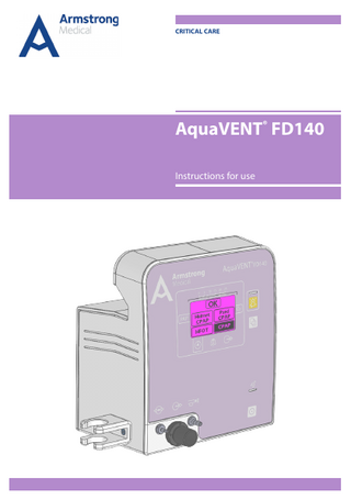
AquaVENT® FD140 Instructions for use
The device operates as described in these instructions for use, enclosed documents and on equipment labelling, provided that it is assembled, operated, maintained and repaired according to the enclosed documentation. The device must be inspected at regular intervals. The device must not be used if found to be defective. Damaged, missing, clearly worn out, warped or contaminated parts must be replaced immediately. If a repair is necessary, the manufacturer and distributor recommend requesting advice via telephone or in writing from the nearest regional service centre. Maintenance and repairs must only be carried out at the service centre or by specialists authorised by the manufacturer. The user of the device shall have sole responsibility for any malfunction or damage which is due to improper use, poor maintenance, improper service, improper repairs or modifications carried out by unauthorised persons. The devices are provided with serial numbers. Their code system includes the product group code, year of manufacture and ascending production number for unique identification. 75XX1234 XX represents a number which indicates the year of manufacture: 15 = 2015, 16 = 2016, etc.
0 Contents 0 Contents
1
1 Introduction 1.1 About this manual 1.2 Symbols used in the instructions for use and on the device 1.3 Abbreviations used in the instructions for use and on the device
5 6 7 8
2 Safety 2.1 Safety precautions
9 10
3 General description 3.1 Intended use 3.2 Main components 3.3 Operation 3.4 Operating principle 3.4.1 CPAP mode 3.4.2 High Flow Oxygen Therapy (HFOT) mode 3.4.3 Helmet CPAP mode 3.4.4 Paed CPAP mode
15 16 17 19 19 19 19 19 20
4 Preparing the device for operation 4.1 General information 4.2 Power supply 4.2.1 Mains supply 4.2.2 Rechargeable battery 4.3 Gas supply 4.3.1 Two-gas operation 4.3.2 Single-gas operation 4.4 CPAP breathing circuit 4.5 CPAP or Paed CPAP with face mask, unheated 4.6 CPAP or Paed CPAP with face mask, heated 4.7 Nebulised drug delivery 4.8 High Flow Oxygen Therapy (HFOT) mode 4.9 Helmet CPAP application 4.10 Placement of the device
21 22 22 22 23 25 25 26 26 27 28 30 30 32 33
®
Instructions for Use, AquaVENT FD140, Rev. 12
1
0 Contents
2
5 Operation 5.1 Switching power on and off 5.2 System test 5.3 Mode selection 5.4 Standby 5.5 Parameter adjustment 5.5.1 Changing patient airway pressure during therapy 5.5.2 Treatment duration 5.5.3 FiO2 5.5.4 Flow adjustment 5.6 Patient menu 5.6.1 Alarm volume 5.6.2 Apnoea alarm 5.6.3 P max 5.6.4 P min 5.6.5 F max 5.7 Starting/ending therapy 5.8 Activating/deactivating the nebuliser
35 36 38 39 41 42 42 43 44 45 47 47 48 48 49 49 50 51
6 Alarms and messages 6.1 Alarms 6.2 Messages 6.2.1 Messages during the system test 6.2.2 Messages during the CPAP test
55 56 59 60 62
7 Cleaning 7.1 General information 7.2 Cleaning and disinfection
65 66 67
8 Maintenance 8.1 General information 8.1.1 Annual maintenance 8.1.2 Maintenance every two years 8.1.3 Maintenance every six years 8.1.4 Maintenance every 12 years 8.2 O2 sensor calibration
69 70 70 70 71 71 72
9 Technical specifications 9.1 General information 9.2 Supply 9.2.1 Power supply 9.2.2 Gas supply ® 9.3 Technical specifications of the AquaVENT FD140 9.4 Increments and intervals of parameter settings 9.5 Default settings
75 76 77 77 77 78 78 78 ®
Instructions for Use, AquaVENT FD140, Rev. 12
0 Contents
9.6 Measuring functions 9.7 Paramagnetic oxygen sensor 9.8 Display 9.9 Alarms 9.10 External communication 9.11 Guidance and manufacturer's declaration 10 Navigation & accessories 10.1 Navigation 10.2 Accessories
®
Instructions for Use, AquaVENT FD140, Rev. 12
79 79 79 79 80 80 87 88 92
3
0 Contents
- This page is intentionally blank. -
4
®
Instructions for Use, AquaVENT FD140, Rev. 12
1 Introduction
In this chapter 1.1 About this manual 1.2 Symbols used in the instructions for use and on the device 1.3 Abbreviations used in the instructions for use and on the device
®
Instructions for Use, AquaVENT FD140, Rev. 12
6 7 8
5
1 Introduction
1.1 About this manual These instructions for use describe the intended use of the following product: ®
AquaVENT FD140 with software version 1.13.0 and hardware version 1.02 For a list of the approved accessories, please refer to chapter 10.2 Accessories. These instructions for use have been compiled with the greatest care. The authors are grateful for any advice, suggestions and constructive criticism. The contact details are stated on the back cover. The manufacturer reserves all rights regarding the circuit diagrams, methods used, name and the right to further develop the AquaVENT® FD140 or to make changes in the interest of technical progress.
6
®
Instructions for Use, AquaVENT FD140, Rev. 12
1 Introduction
1.2 Symbols used in the instructions for use and on the device Refers to dangerous situations which may occur when failing to observe the present instructions for use. Refers to a situation which may cause injuries to the user or
Warning the patient.
Refers to a situation which may cause damage to the
Caution equipment.
All warnings and precautions must be read and observed. Scale for the bar graph indicating patient pressure. Treatment duration in minutes:seconds Respiratory rate Applied flow (symbol below display) Alarm pause key Menu key Measuring line connection (pressure) Respiratory gas outlet (symbol above tube connection) Nebuliser port
®
Instructions for Use, AquaVENT FD140, Rev. 12
7
1 Introduction
Power indicator Three-level capacity indicator of the rechargeable battery ON/OFF key Serial interface The AquaVENT® FD140 corresponds to Directive 93/42/EEC concerning medical devices, provided it is operated according to the instructions for use. "0123" is the identification number of the notified body. Follow the instructions for use. The AquaVENT® FD140 must not be disposed of with ordinary, unsorted household waste but must be treated separately. Please contact the manufacturer for more information regarding the disposal of the AquaVENT® FD140.
1.3 Abbreviations used in the instructions for use and on the device AIR O2 CPAP PEEP FiO2 HFOT HW SW Ser. No.
8
Medical air Medical oxygen Continuous Positive Airway Pressure, measured and set CPAP value Positive end-expiratory pressure Inspiratory oxygen concentration High Flow Oxygen Therapy mode Hardware version Software version Serial number
®
Instructions for Use, AquaVENT FD140, Rev. 12
2 Safety
In this chapter 2.1 Safety precautions
10
®
Instructions for Use, AquaVENT FD140, Rev. 12
9
2 Safety
2.1 Safety precautions Reference: These instructions for use describe the product: ®
AquaVENT FD140 CPAP respiratory therapy device Software version 1.13.0 Hardware version 1.02 Safe operation: ®
In order to guarantee the safe operation of the AquaVENT FD140, the ® device must only be used as described. Before putting the AquaVENT FD140 into operation, users must familiarise themselves with these ® instructions for use. Only instructed staff are allowed to use the AquaVENT FD140. As a matter of principle, all directions in these instructions for use and all legal provisions must be observed for the use of this respiratory therapy device. Classification: ®
The AquaVENT FD140 is a Class IIb device according to Directive 93/42/EEC concerning medical devices, Annex IX, section 1.3, rule 3, section 3.1, rule 9 and section 3.2, rule 11. Classification according to EN 60601-1 Medical electrical equipment General requirements for basic safety and essential performance: DEVICE OF PROTECTION CLASS I, with earth conductor for protection against electric hazards. CONTINUOUS OPERATION if applied in compliance with the INTENDED USE and within the indicated temperature limits. Service and maintenance: ®
To ensure its safety and proper functioning, the AquaVENT FD140 should be checked once every year. Repairs, service and maintenance on the device must only be carried out by authorised service technicians. For maintenance intervals and measures to take, please refer to chapter 8 Maintenance.
10
®
Instructions for Use, AquaVENT FD140, Rev. 12
2 Safety
Safety functions: ®
The following safety functions were implemented in the AquaVENT FD140 in order to warn the user if the patient is at risk: Device alarms: Monitoring
Monitoring for
of AIR gas supply, of O2 gas supply
loss of AIR supply, loss of O2 supply
of the sensors
FiO2, flow, pressure
of mains power supply
loss of mains power
of the rechargeable battery
sufficient battery capacity
All device alarms are evaluated during the treatment and in standby mode. Where necessary, the alarm indication is triggered. Patient safety: The patient connected to the device requires surveillance by specialist staff. If a patient is connected to the system, make sure that the alarm limits are adapted to the patient condition and the alarms are activated. Each time the device is turned on, a system test is automatically carried out. The system test ensures that all safety-related functions and components are tested before the device is used. For detailed information, please refer to chapters 5.2 System test and 6 Alarms and messages. Accessories: ®
The AquaVENT FD140 is offered with original accessories. Do not use accessories other than those specified in chapter 10.2 Accessories. For details, please refer to chapter 1.1 About this manual.
®
Instructions for Use, AquaVENT FD140, Rev. 12
11
2 Safety
Electrical hazard: ®
The AquaVENT FD140 is exclusively designed for use in an electrical environment according to VDE 0100 part 710 or EN 60601-1. ® The AquaVENT FD140 must not be used if there are doubts concerning the quality and function of the protective earthing of the electrical installation. The housing must be dry before the device is connected to the mains supply. It must be ensured that the supply voltage corresponds to the ratings on the type plate on the back panel of the device. The system must be stored and operated at the temperature and humidity levels indicated in chapter 9. If the housing temperature is higher or lower than the indicated operating range, wait approx. one hour prior to use to allow the system to adjust to the room temperature. The system must always be disconnected from mains supply before any cleaning, repair or maintenance is carried out. Fire hazard: ®
The AquaVENT FD140 must not be used in potentially explosive atmospheres or in the presence of flammable anaesthetics. Risk of electromagnetic disturbance: Devices which generate electromagnetic field strengths at levels exceeding the limit values of EN 60601-1-2 and are installed in the vicinity of the system can affect the safe operation of the device and endanger the patient. ® The use of mobile telephones in the vicinity of the AquaVENT FD140 can affect the safe operation of the device and endanger the patient. ®
Warning
The AquaVENT FD140 must not be used in close proximity to nuclear magnetic resonance equipment (MRI, NMR devices).
Electromagnetic compatibility: ®
The AquaVENT FD140 is only intended for use in an electromagnetic environment in which radiated RF disturbances are controlled. The users of ® the AquaVENT FD140 can contribute towards avoiding electromagnetic interference by maintaining the minimum distance between portable and mobile high frequency communications equipment (transmitter) and the ® AquaVENT FD140.
12
®
Instructions for Use, AquaVENT FD140, Rev. 12
2 Safety
The use of other electrical devices, e.g., power cords, decreased Warning may result in increased emissions or ®
immunity performance of the AquaVENT FD140. This may put the patient at risk. ®
Caution
Note
Using other electrical devices with the AquaVENT FD140 or in its vicinity can cause interference. The correct performance of the device must be verified prior ® to connecting the patient to the AquaVENT FD140.
Detailed information on electromagnetic compatibility can be found in chapter 9.11 Guidance and manufacturer's declaration.
®
Instructions for Use, AquaVENT FD140, Rev. 12
13
2 Safety
- This page is intentionally blank. -
14
®
Instructions for Use, AquaVENT FD140, Rev. 12
3 General description
In this chapter 3.1 Intended use 3.2 Main components 3.3 Operation 3.4 Operating principle 3.4.1 CPAP mode 3.4.2 High Flow Oxygen Therapy (HFOT) mode 3.4.3 Helmet CPAP mode 3.4.4 Paed CPAP mode
16 17 19 19 19 19 19 20
®
15
Instructions for Use, AquaVENT FD140, Rev. 12
3 General description
3.1 Intended use ®
The AquaVENT FD140 is a clinical respiratory therapy device which assists respiration with constant positive air pressure (CPAP and HFOT), and can be used for administering aerosol medication. The connected patient (without direct supervision by staff or monitoring equipment) must be ® awake and breathe spontaneously. The AquaVENT FD140 is not a lifesupport device. CPAP therapy can be applied in different modes and via face mask or ® helmet. Furthermore, the AquaVENT FD140 can be used as a flow generator for High Flow Oxygen Therapy (HFOT) mode. ®
The AquaVENT FD140 is designed for use with adults and children greater than 5 kg in weight. ®
The AquaVENT FD140 is equipped with a paramagnetic oxygen sensor. This sensor continuously measures FiO 2, which is displayed on the screen. The oxygen sensor is maintenance-free and needs to be calibrated only once a year. It is also equipped with an internal rechargeable battery with an integrated mains power failure alarm.
16
®
Instructions for Use, AquaVENT FD140, Rev. 12
3 General description
3.2 Main components Front:
Alarm pause key Touch screen
Menu key
Pressure measuring line connection
Power indicator ON/OFF key
Respiratory gas outlet
®
Nebuliser port
Instructions for Use, AquaVENT FD140, Rev. 12
17
3 General description
Back:
Serial interface Power input
O2 inlet AIR inlet Type plate
Display: Patient airway pressure (bar graph)
Nebuliser
Patient airway pressure (set value)
FiO2 Battery capacity indication
Treatment duration Respiratory rate
18
Flow indication
®
Instructions for Use, AquaVENT FD140, Rev. 12