AquaVENT
GGM VH-2600A Technical Manual July 2015
Technical Manual
27 Pages
Preview
Page 1
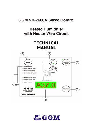
GGM VH-2600A Servo Control Heated Humidifier with Heater Wire Circuit TECHNICAL MANUAL
CONTENTS PAGE 1.0 Introduction VH-2600A----------------------------------------------------------------------------------------
of
1.1 Application and Description-------------------------------------------------------------------------------------------1.1.1 Intended Use--------------------------------------------------------------------------------------------------------1.1.2 Contraindication----------------------------------------------------------------------------------------------------1.2Definitions------------------------------------------------------------------------------------------------------------------
1 1 1 1 1
2.0 Product Specifications------------------------------------------------------------------------------------------- 2 2.1 Transport and Storage---------------------------------------------------------------------------------------------------- 4 2.2 Statement on Environmental Issues------------------------------------------------------------------------------------ 4
3.0 Explanation of Controls and Indications---------------------------------------------------------------------- 5 4.0 Setting up the Humidifier--------------------------------------------------------------------------------------- 9 5.0 Operating the Humidifier---------------------------------------------------------------------------------------- 10 5.1 Basic Steps---------------------------------------------------------------------------------------------------------------- 10 5.2 Setting the Airway Temperature and the Chamber Temp----------------------------------------------------------- 12 5.2.1 Circuits with a Heater Wire---------------------------------------------------------------------------------------- 12 5.2.2 Circuits without a Heater Wire------------------------------------------------------------------------------------ 13 5.3 Circuit Operation--------------------------------------------------------------------------------------------------------- 13 5.3.1 Introduction---------------------------------------------------------------------------------------------------------- 13 5.3.2 Control Board-------------------------------------------------------------------------------------------------------- 13 5.3.3 Power Board--------------------------------------------------------------------------------------------------------- 13
6.0 Sterilization of Reusable Parts--------------------------------------------------------------------------------- 14 7.0 Routine Maintenance-------------------------------------------------------------------------------------------- 15 7.1 Calibration Check of Temperature Probes---------------------------------------------------------------------------- 15 7.2 Monthly checks----------------------------------------------------------------------------------------------------------- 15
8.0 Servicing Information------------------------------------------------------------------------------------------- 16 8.1 Introduction--------------------------------------------------------------------------------------------------------------- 16 8.2 Printed Circuit Board Removal----------------------------------------------------------------------------------------- 16 8.2.1 Control PCB--------------------------------------------------------------------------------------------------------- 16 8.2.2 Power PCB----------------------------------------------------------------------------------------------------------- 16
9.0 Schematics, Part Lists and Mechanical Drawing------------------------------------------------------------ 17 9.1 VH-2600A Circuit Layout Block Diagram----------------------------------------------------------------------------9.2 Component Layout – Power Board-----------------------------------------------------------------------------------9.3 VH-2600A spare Parts List and Exploded Diagram------------------------------------------------------------------9.4 VH-2600A Heater Plate Parts List and Exploded Diagram-----------------------------------------------------------
17 18 20 23
1.0 INTRODUCTION of VH-2600A 1.1 Application and Description The VH-2600A is mandatory for all patients requiring mechanical ventilation and to be used in the Medical Intensive Unit. It is to provide humidity and heated temperature to gases for the patients. Warning: z The use of breathing circuits, chambers and other accessories which are not authorized by GGM may cause malfunction, damages or injuries. z Before servicing, always disconnect the supply. z Make sure the invasive mode is set for patients having bypassed airways.
1.1.1 Intended use The GGM Dual Servo Controlled Heated Respiratory Humidifiers are intended to be used to warm and add humidity to gases delivered to patients who require mechanical ventilation or positive pressure breathing assistance via an endotracheal tube or face mask. The warmth and moisture is supplied by passing the gas over heated water and the temperature of the gas flowing through the breathing circuit can be maintained by a heater wire. Temperature is controlled accurately and measured via temperature probes located at the the patient end of the delivery tube and at the humidification chamber outlet. The use of the two heating systems also provides control over the level of humidity delivered to the patient. The temperature of the gas at the patient Y-piece is selected using the select knob and the actual temperature of the delivered gas is displayed on the 4 digit LED display. The VH-2600A can be operated with or without a heated wire breathing circuit, and is particularly suitable for all neonatal and critical applications.
1.1.2 Contraindication There is no further contraindication for the use of humidifier.
1.2 Definitions
-1-
Note, Caution, Warning: NOTE: A NOTE provides additional information which is intended to point out procedures or conditions which may otherwise be misinterpreted or overlooked. CAUTION: A CAUTION statement designates the possibility of damage to the equipment if a procedure is not followed exactly. WARNING: A WARNING statement refers to conditions with a possibility of personal injury if a procedure is not followed exactly.
2.0 PRODUCT SPECIFICATIONS Dimensions: W135mm x D170mm x H156mm (without chamber fitted) Weight 2.9 kg (without a chamber fitted) Electrical Rating Supply Frequency: 50 - 60 Hz Supply Voltage: 230V ± 23V Supply Current: 1.0A max at 230V Heater Plate Heater Wire Capacity: 150W Capacity: 60W Maximum Operating : Air inlet
18-25 °C
Temperature Control Range: Invasive mode airway:40 °C Non -Invasive airway:34 °C
Chamber :37°C Chamber :31°C
Display: 4 digit 14mm 14segment LED - Range: 5.0 to 80.0°C, Accuracy: ±0.5 °C (in 25.0 - 40.0°C temperature range) Alarm Parameters: Heater Wire On - Airway Temp: Tracking ± 2°C from set temperature. All models Independent 41°C maximum
- Chamber Temp: Alarms if chamber temperature varies ±4°C from the set chamber one for 20 minutes, or alarms immediately if set chamber temperature is exceeded by 10°C. Heater Wire Off - Airway Temp: Fixed alarms at 41°C high, 29.5°C low. - Chamber Temp: Limited to 66°C maximum (visible indicator only). Standards Compliance Designed to conform to requirements of IEC60601-1, IEC60601-1-2 Classified as: Class 1 Type B Drip Proof Continuous Operation Not to be used in the presence of flammable anesthetics.
-2-
General Information Fuses in this equipment should only be replaced with fuses of the correct type rated as indicated on the appropriate labels or in the Technical Manual. A full technical description including circuit diagrams, parts list and service data is contained in the Technical Manual. The safety, reliability and performance of this equipment is dependent upon: 1. The equipment being operated, maintained and repaired according to the manuals and instructions supplied. 2. All servicing, calibration and repairs being carried out by a qualified service technician. 3. Compliance with the local electrical installation regulations. 4. Maintenance of grounding integrity by connection to a "hospital grade" receptacle. Always disconnect supply before servicing. 5. This product is intended for use by a qualified medical practitioner. Users should ensure that they are totally familiar with the use of the humidifier before connecting the device to a patient. A full technical description including circuit diagrams, parts list and service data is contained in the Technical Manual which is available from your supplier. This product is intended for use by a qualified medical practitioner. Users should ensure that they are totally familiar with the use of the humidifier before connecting the device to a patient. Further information please contact GGM distributor in your country, or contract GGM directly: Great Group Medical Co., Ltd. No.81, Sec 1, Guoguang Rd., Dali City, Taichung 41262, Taiwan Tel. +886.4.2407.1449 ext 103 Fax.+886.4.2407.2796 E-mail : [email protected] www.greatgroup.com.tw
-3-
2.1 Transport and Storage Transport Temperature: -10 to 50 °C (14 to 122 °F) 30 to 95 % relative humidity Storage Temperature: -10 to 50 °C (14 to 122 °F) 30 to 95 % relative humidity
2.2 Statement on Environmental Issue GGM designs, manufactures and markets medical. These activities do not create a great risk to the environment, and therefore it is not viewed as an issue requiring specific management, GGM is certified to ISO13485 and GMP. GGM does recognize the importance of addressing environmental issues, and these are addressed in procedures or by Management Practice as appropriate. Routine audits are carried out as part of the QMS as required by ISO13485 – these also include examination of Environmental issues, Health and Safety as well as the Quality Management aspects. The Company Secretary has been appointed to monitor environmental developments and to take action to ensure that GGM’s activities impact on the environment is minimized. Actions taken include: z All clean cardboard and paper waste is collected for recycling at GGM z Program in place to improve energy efficiency through premises management z Use of near home worker where suitable to minimize unnecessary travel z Use of electronic data transmission and storage to minimize the use of paper, where this is cost effective and available.
WARNING: Any changes and modification without manufacturer’s authorization may cause danger and harmful results.
3.0 Explanation of Controls and Indicators 3.1 VH-2600A Front Panel
1.
Airway/Chamber Temperature Display: Display the actual temperature of gas being delivered from the chamber or if the hold the Function(2) and Heater wire(3) buttom, it also displays the Airway temperature.
2. FUNCTION BUTTOM a.Locked / Unlock: *System will automatic “Lock” the panel after power on, and display the chamber temperature. *Hold FUNCTION for 3 sec=> Unlock *Hold FUNCTION for 3 sec=> lock [* The system will relock automaticly in 5 sec, if no further operation. b. Patient mold selection: *The system default setting to be “invasive” mold , *Change to “Non-Invasive”mold from “Invasive” mold Hold
FUNCTION for 3 secs + Push FUNCTION 1 times and system will swift to “Non-Invasive”mold
*Change to “Invasive”mold from “Non-Invasive” mold Hold
FUNCTION for 3 secs + Push FUNCTION 1 times and system will swift to “Invasive”mold
c. Selection Display Parameter: *Default setting of display :
Chamber temperature
*How to display Airway temperature Hold FUNCTION for 3 secs + Push Heater Wire 1 times and display will swift to ==>Airway temperature ,after 5 sec will swift back to Chamber temp. * Hold FUNCTION for 3 secs + Push Heater Wire 1 times + Hold FUNCTION for 3 secs ==> Airway Temperature, and maintain on display Airway Temperature * Hold FUNCTION for 3 secs + Push Heater Wire 2 times ==>Heater Plate temperature will display for 5 sec , swift back to Chamber temp * Hold FUNCTION for 3 secs + Push Heater Wire 2 times + Hold FUNCTION for 3 secs ==> Heater Plate temperature maintain on display Heater plate temperature, Push MUTE To swift from Airway or Heater Plate temperature Ö Chamber temperature Ö
Attention: push the button “Be” 1 sound will be heard hold button 3 sec “Be” 2 sounds will be heard
3. HEATER-WIRE The system will automatically swift to “ Heater Wire ON” mold , when the system equipped with heater wire while power on , and the LED will be illuminated, Swift to “ Heater Wire OFF” mold ” ,Hold Heater wire ”for 3 sec and LED will be off, and it is in “ Heater Wire off”mold 【Attendtion:1.it will be not able to swift to “heater wire off” mold , if the heater still connect with the system 2. the alarm will happen when you connect the heater wire again in “heater wire off” mold
4. Patient Mold indicator * Invasive mold default setting Heater wire ON mold Airway :40℃ Chamber :37℃。 Heater wire OFF mold Airway : 34℃, Chamber :31℃。
Non-Invasive mold default setting Heater wire ON mold Airway :37℃ Heater wire OFF mold Airway : 31℃,
5. MUTE BUTTON Will silent all alarm sound for 3 min, the alarm indicator will keep on flashing until the alarm situation improved.。
Alarm indicator 7. TEMPERATURE PROBE:< Alarm> While the temperature probe does not well connected or defected, system will alarm with sound and flashing red LED.
8. HEATER WIRE: < Alarm> *While the heater wire does not well connected or defected, * while connect with heater wire in Heaterwire Off mold system will alarm with sound and flashing red LED.
9. CHAMBER TEMPERATURE HIGH: <Alarm> * While the chamber temp higher than 4°C from setting temp and continuous 20 min * while the chamber temp higher than 10°C from setting temp system will alarm with sound and flashing red LED Attention: alarm will disable while in Heaterwire Off mold , and alarm will happen while the chamber higher than 66°C
10. AIRWAY TEMPERATURE HIGH: <Alarm> > * While the airway temp higher than 2°C from setting temp * while the airway temp higher than 42°C system will alarm with sound and flashing red LED
11. CHAMBER TEMPERATURE LOW: < Alarm> * While the chamber temp lower than 4°C from setting temp and continuous 20 min 。Attention: alarm will disable while in Heaterwire Off mold , 12. AIRWAY TEMPERATURE LOW: < Alarm> * While the airway temp lower than 2°C from setting temp 13. SEE MANUAL : <Alarm> When the red LED illuminates, a microprocessor fault occurred and system will be no function, the system should be disconnected from patient and call service center for repair
3.2 Right Side Panel
1. HEATER WIRE POWER SOCKET The heater wire power connection plugs into this socket. 2. TEMPERATURE PROBE SOCKET
The temperature probe plugs into this socket. 3. MAINS SWITCH Turns power to the humidifier on and off.
3.3 Left Side Panel
1. POWER CORD Connect the humidifier to an AC power source as indicated on the side panel.。
2. Product labeling Product number Power supply Series number
3.4 Electrical Rating: Supply Voltage: AC 230V±23V or AC 115V±12V Supply Frequency:50Hz / 60Hz 。
3.4 Safety protection Over current protection:115V/3A(fast burn type) 230V/1.5A(fast burn type) 。 。 Over heat protection:115±3℃ thermostat(manual restetype)
4.0 Setting up the Humidifeir
1 . S e l e c t a s u i t a b l e G G M h u m i d i f i c a t i o n c h a m b e r . R e f e r t o t h e c h a m b e r in s t r u ct i o n s h e e t f o r chamber details. Ensure that the chamber base and heater plate are undamaged, clean and dr 2. Slide the humidification chamber onto the heater plate. Push the chamber as far onto the plate as possible. The finger guard will automatically lock the chamber in place. 3. If using an auto feed chamber, suspend a sterile water bag above the humidifier and connect the chamber according to the instructions for use provided in the chamber carton. Water will automatically be supplied to the chamber as required. 4. If using any other GGM chamber, fill with sterile, deionized water to the maximum water level line. 5. Connect a tube from the gas supply to the inlet port of the chamber. (Pic 1&2) 6. Connect the inspiratory side of the circuit to the outlet port of the chamber. (Pic 1&2) 7. If using a heated wire circuit, connect the heater wire power connection to the heater base and to the heater wire assembly. (Pic 1&2) 8. Select a GGM dual temperature probe of similar length to the chosen breathing circuit. Push the temperature probe plug into the socket on the side of the heater base. 9. Place the “T-shaped” or first temperature probe sensor into the port on the side of the heater wire assembly. Push in firmly to ensure the tip of the sensor is in the middle of the airflow. 10. Place the second temperature probe sensor into the port at the end of the inspiratory limb. This is normally in the Y-piece. For reusable circuits ensure that the end of the heater wire is between 25 - 100mm (1" - 4") from the temp sensor. For disposable circuits ensure that the end of the heater wire is no more than 25mm (1") away from the temperature sensor. T h e h e a t e r wi r e m u s t n o t t o u c h t h e s e n s o r . T h e h u m i d i f i e r i s n o w r e a d y t o b e t u r n e d o n . 11. To remove the chamber, push down on the finger guard. Pull the chamber forward until the rim is just touching the finger guard. Remove fingers from the guard and pull the chamber the rest of the way off the heater plate. Use this technique to avoid touching the hot heater plate or chamber base. NOTE: Breathing circuits and humidification chambers should be replaced regularly in accordance with hospital infection control procedures.
Pic 1: Non heater wire circuit
Pic 2: Heater wire circuit WARNING: * When mounting a humidifier adjacent to a patient, ensure that the humidifier is always positioned lower than the patient. * DO NOT fill the chamber above the maximum fill level line. Liquid could enter the breathing circuit if the chamber is overfilled. * DO NOT fill the chamber with water in excess of 37°C. * Ensure that both temperature probe sensors are correctly and securely fitted. Failure to do so may result in temperatures in excess of 41°C being delivered to the patient.
5.0 OPERATING THE HUMIDIFIER 5.1 Basic Steps 1. Plug the humidifier power cable into an AC supply of the voltage and maximum power rating specified on the side label of the unit. 2. Ensure that the humidification chamber and breathing circuit are installed and connected correctly, 3. Switch on the ventilator or gas supply. Carry out flow and pressure testing applicable to the ventilator in use. 4. Switch on the humidifier using the switch at the side. The following information will then be displayed for a period of 1 second each: -Company name “GGM” -Model number eg. VH-2600A -Software version eg. REV1.0 -Set airway temperature (in °C) eg. “A40.0 -Set chamber temperature) eg.C37.0 5. If the display shows anything other than a temperature after the start-up sequence is completed, the unit should be removed from the patient circuit and sent to a qualified service technician. 6. If a heated wire circuit is being used, check that the green indicator light next to the button labeled “heater wire” is illuminated. If not, press the button firmly. Ensure that the green light remains illuminated when the button is released.
7. FUNCTION BUTTOM a.Locked / Unlock: *System will automatic “Lock” the panel after power on, and display the chamber temperature. *Hold FUNCTION for 3 sec=> Unlock *Hold FUNCTION for 3 sec=> lock [* The system will relock automaticly in 5 sec, if no further operation.
b. Patient mode selection:
*The system default setting to be “invasive” mode ,
invasive mode
*Change to “Non-Invasive”mode from “Invasive” mode Hold
FUNCTION for 3 secs + Push FUNCTION 1 times and system will swift to “Non-Invasive”mode
*Change to “Invasive”mode from “Non-Invasive” mode Hold
FUNCTION for 3 secs + Push FUNCTION 1 times and system will swift to “Invasive”mode
c. Selection Display Parameter: *Default setting of display : Chamber temperature *How to display Airway temperature Hold FUNCTION for 3 secs + Push Heater Wire 1 times and display will swift to ==>Airway temperature ,after 5 sec will swift back to Chamber temp. * Hold FUNCTION for 3 secs + Push Heater Wire 1 times + Hold FUNCTION for 3 secs ==> Airway Temperature, and maintain on display Airway Temperature * Hold FUNCTION for 3 secs + Push Heater Wire 2 times ==>Heater Plate temperature will display for 5 sec , swift back to Chamber temp * Hold FUNCTION for 3 secs + Push Heater Wire 2 times + Hold FUNCTION for 3 secs ==> Heater Plate temperature maintain on display Heater plate temperature, Push MUTE To swift from Airway or Heater Plate temperature back to Chamber temperature Ö
Attention: push the button “Be” 1 sound will be heard hold button 3 sec “Be” 2 sounds will be heard
8. HEATER-WIRE The system will automatically swift to “ Heater Wire ON” mode , when the system equipped with heater wire while power on , and the LED will be illuminated, Swift to “ Heater Wire OFF” mode ” ,Hold Heater wire ”for 3 sec and LED will be off, and it is in “ Heater Wire off”mode
【Attendtion:1.it will be not able to swift to “heater wire off” mode , if the heater still connect with the system 2. the alarm will happen when you connect the heater wire again in “heater wire off” mode
9. Patient Mode indicator * Invasive mode default setting Heater wire ON mode Airway :40℃ Chamber :37℃。 Heater wire OFF mode Airway : 34℃, Chamber :31℃。
Non-Invasive mode default setting Heater wire ON mode Airway :37℃ Heater wire OFF mode Airway : 31℃,
9 .Periodically check that the airway temperature displayed is close to the set temperature. 10. If the gas flow is stopped or interrupted, the humidifier turned off.
WARNING: *Unless the cause and effects of any alarm are understood and assessed to be of no hazard to the p atient, the humidifier should be immediately switched off and disconnected from the patient. *The temperature delivered to the patient may exceed 41°C if the airway temperature probe is not inserted correctly at the patient end of the inspiratory circuit . * Do not touch the heater plate as the surface temperature may exceed 85°C. Other accessible metal surfaces may exceed 55°C *Always ensure the gas supply is flowing through the humidifier before connecting to the patient. *DO NOT use a heated wire breathing circuit in the presence of flammable anaesthetics, (this does not include pure oxygen). Verify with gas manufacturer that degradation of anaesthetic agents will not occur. 11 * Do no t f i l l th e cha mb er p a st t h e m a xim um wa t e r l e ve l mar k. M on i tor t h e wa t e r l e ve l i n th e chamber (or water bag for continuous feed chambers) and refill as necessary. *The liquid output of the humidifier may exceed 44 mg/L if operating temperatures greater than 37°C are selected.
*Electric shock hazard - do not remove cover. In case of a fault, refer to a qualified service technician. *The power rating of the outlet socket on some ventilators may be less than the maximum required by the humidifier. See Section 2.0 for details. *The function of this humidifier may be adversely affected by the operation of high frequency surgical apparatus, shortwave or microwave equipment in the vicinity. *Some pressure regulated neonatal ventilators may cause the generation of high temperatures to reach the patient upon disconnection and reconnection of the inspiratory limb, or disconnection only of the expiratory limb. To prevent this occurring, it is recommended that the humidifier is either placed in Standby Mode or switched off 5 minutes before disconnection. *To Keep the temp probe outside the incubator or blanket for good operation of humidifier during neonate ventilation .
5.2 Setting the Airway Temperature and the Chamber Temp 5.2.1 Circuits with a Heater Wire WithVH-2600A attach a circuit with a heater wire and ensure that the heater wire button has been pressed until the green light is illuminated. Use of a heated wire circuit means the humidifier now has two independent heating systems – the heater plate which heats the water (and therefore the gas in the chamber) and the heater wire. The heater wire maintains the temperature of the gas as it travels along the circuit, eliminating condensation and the need for a water trap. It also means that high temperatures at the chamber outlet are no longer necessary to ensure suitable patient gas temperature. - 12 5.2.2 Circuits without a Heater Wire The HEATER WIRE button must be pressed until the green light is no longer illuminated and then released. In this mode, the temperature of the gas delivered to the patient is maintained by the heater plate only and this is controlled by the patient temperature probe. The temperature probe at the chamber outlet monitors and limits the temperature of the gas at this point to a maximum of 66°C. It is recommended that the humidifier is set to deliver inspiratory gases at no less than 37°C, 100% RH at the tracheal tube, in order to optimize mucociliary transport. To achieve this, set the airway temperature to approximately 39°C, depending on the length of unheated tubing between the Y-piece and the patient. Gas leaves the humidification chamber at approximately 50°-65°. It cools as it moves along the breathing circuit towards the patient, and condensation forms. A water trap must be used to collect condensation.
-
o
e
s
- 12 -
5.2.2 Circuits without a Heater Wire The HEATER WIRE button must be pressed until the green light is no longer illuminated and then released. In this mode, the temperature of the gas delivered to the patient is maintained by the heater plate only and this is controlled by the patient temperature probe. The temperature probe at the chamber outlet monitors and limits the temperature of the gas at this point to a maximum of 66°C. It is recommended that the humidifier is set to deliver inspiratory gases at no less than 37°C, 100% RH at the tracheal tube, in order to optimize mucociliary transport. To achieve this, set the airway temperature to approximately 39°C, depending on the length of unheated tubing between the Y-piece and the patient. In some applications these temperature and humidity levels may not be required, so the patient temperature may be set lower. 39°C 37°C ≈55°C eg. Set Temperature = 39°C Gas leaves the humidification chamber at approximately 50°-65°. It cools as it moves along the breathing circuit towards the patient, and condensation forms. A water trap must be used to collect condensation.
5.3 CIRCUIT OPERATION 5.3.1 INTRODUCTION This section describes briefly the operation of each of the circuit sections. Refer to the circuit diagrams in § 8.5 to 8.8.
5.3.2 CONTROL BOARD The one basic control board, with various discreet hardware changes, provides the controlling functions for the VH-2600A humidifiers. Each model however is controlled by a unique software version. temperature.
5.3.3 POWER BOARD
- 13 -
6.0 STERILIZATION OF REUSABLE PARTS
- 14 -
7.0 ROUTINE MAINTENANCE 7.1 Calibration Check of Temperature Probes Temperature probes should be checked every twelve months to ensure they are operating within manufacturer’s specifications. The following procedure should be carried out by a technician: 1. Obtain a good mercury thermometer. 2. Place the thermometer and the patient end of the probe into a container of lukewarm water which is between 32°C and 40°C. 3. Turn the humidifier on and set the control knob to maximum. Allow the temperature of the probe and thermometer to stabilize. When stable, compare the temperature displayed on the display to the reading on the thermometer. 4. The display should be within ± 0.5°C of the thermometer reading. If not, then it is recommended that the probe is replaced. 7.2 Monthly Checks Check the temperature probe for damage to sensor tips, abrasion of the cable or tarnishing of electrical contacts. Replace if necessary. Probes with gold plated electrical contacts may be ethylene oxide sterilized; other parts should be cleaned with alcohol on a swab. The heater base may be cleaned by using a mop cloth. Check the humidifier cables for damage and replace when necessary. Plug a probe and heater wire assembly into the heater base, switch on and observe that the humidifier conducts the self test. Observe correct operation of self test. Check for correct display of ambient temperature and that no alarms are immediately actived. Ensure the heater plate surface is clean and free from pitting, gouging etc. These can be removed by sanding lightly.
Keep routine maintenance to ensure safety for continuous usage.
- 15 -
8.0 SERVICING INFORMATION 8.1 INTRODUCTION This section provides information for servicing the VH-2600A Humidifier. The electronic circuitry is contained on two s e p a r a t e circuit boards, the power board and control board. Please note the following: • Follow ESD precautions when handling circuit boards.
8.2 PRINTED CIRCUIT BOARD REMOVAL
8.2.1 CONTROL PCB The front panel and heater plate assembly is separated from the humidifier body by removing the 4 fixing screws from the rear of the humidifier body. The front panel assembly can now be moved aside and the two ribbon cable connectors (J1 and J2) disconnected from the rear of the control board. If the front panel is now positioned face down the three plastic retaining latches protruding through the board can be moved in the appropriate direction to release the board. This is facilitated if a slight upward finger pressure is maintained on either edge of the board, when the latches release, the board will pop up leaving the push on control knobs behind in the front panel. 8.2.2 POWER PCB Separate the case front from the humidifier body and disconnect the two ribbon cable connectors joining the Power PCB and Control PCB (J1 and J2). Cut the cable tie holding the heater plate and chassis wires together. The power board and heat sink assembly can now be removed by flexing the case sides away from the top edge of the board and moving the board forward slightly to disengage from the case. The board should now be lifted slightly to clear the lower retaining guides and moved further forward to gain access to the various wiring harness connectors which can now be detached. Before removing the PCB, unscrew the mains cord connections and cut the cable tie holding the mains cord in place.
- 16 -