ARJO Huntleigh Healthcare
Patient Lifting Equipment
BHM MINISTAND MODELS 865XXX and 866XXX Technical Manual Rev 5 April 2005
Technical Manual
33 Pages
Preview
Page 1
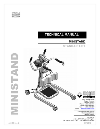
MODELS 865XXXXX 866XXXXX
TECHNICAL MANUAL MINISTAND STAND-UP LIFT
2001, Tanguay Street Magog (Quebec) Canada J1X 5Y5 Phone: (819) 868-0441 Toll free: 1 800-868-0441 Fax: (819) 868-2249 E-mail: www.bhm-medical.com 5155 Spectrum Way, Unit 33 Mississauga (Ontario) Canada L4W 5A1 14 Cross St. London, SW13 0PS, United Kingdom Tel: +44 (0)7740 717146 Fax: +44 (0)870 1619681 Avril 2005 (rev. 5)
#001.20076
TABLE OF CONTENTS SYMBOLS ...4 TECHNICAL DATA ...5 SAFETY INSTRUCTIONS & WARNINGS ...6 GENERAL...6 SHOCK PREVENTION ...8 FIRE AND EXPLOSION ...8 EQUIPMENT WARNING LABELS ...8 ASSEMBLY INSTRUCTIONS ...9 Assembly Instructions for Ministand Lift ...9 ADJUSTING THE WIDTH OF THE LEGS ...13 LIFT ASSEMBLY EXPLODED VIEW ...14 With shifter base ...14 With pedal base ...15 With power base ...16 LIFT PARTS LIST...17 SHIFTER BASE EXPLODED VIEW...18 #700.20061.09 (SHIFTER BASE KIT ASSEMBLY) ...18 PEDAL BASE EXPLODED VIEW...19 #700.20060.09 (PEDAL BASE KIT ASSEMBLY)...19 POWER BASE EXPLODED VIEW ...20 #700.20062.09 (POWER BASE KIT ASSEMBLY)...20 CONTROL BOX DETAILS (with integrated charger)...21 BATTERY PACK DETAILS ...22 CHARGER WIRING DETAILS ...23 BATTERY & CONTROL BOX WIRING DETAILS (with integrated charger) ...24 BATTERY MAINTENANCE & SERVICE ...25 MAINTENANCE AND REPLACEMENT OF BATTERIES...25 MAINTENANCE & SERVICE ...26 MAINTENANCE AND REPLACEMENT OF BATTERIES...26 MONTHLY INSPECTION DETAILS...28 DIAGRAM ...29 LOGBOOK...30 WARRANTY ...33
COPYRIGHT 2003 WARNING! All rights reserved. CONFIDENTIAL. The reproduction of this document or the transmittal in any form of any information, contained herein, without the authority in writing of an officer of the manufacturer is prohibited. TECHNICAL SPECIFICATIONS AND DESIGN SUBJECT TO CHANGE WITHOUT NOTICE.
3
SYMBOLS WARNING: this symbol is intended to alert the user to hazards or unsafe practices which could result in serious bodily harm.
CAUTION: this symbol is intended to alert the user of the presence of important operating and maintenance instructions which could prevent product damage or possible personal injury.
NOTE: this symbol offers helpful information concerning certain operating procedures. CONSULT ACCOMPANYING DOCUMENTS
BOOM "UP"
BOOM "DOWN" INDICATES CHARGING MODE
BASE "CLOSED"
INDICATES CHARGER POWER IS "ON"
BASE "OPENED"
DO NOT ATTEMPT TO USE THIS EQUIPMENT WITHOUT UNDERSTANDING THIS MANUAL. To ensure safe operation, carefully read the entire manual, especially the section on Safety Instructions and Warnings , before installing, operating or servicing this equipment. If anything is not completely understood, please contact your supplier for more details. Failure to comply with warnings in this manual may result in injury. Keep this manual with lift and refer to it as required. Contents of this manual are subjected to change without prior notice to users.
4
TECHNICAL DATA
DIMENSIONS
WEIGHT DATA Hoisting height at:
Description
Min
Description
Max.
kg
lbs
Total lift
45.5
100
mm
in
mm
in
Shipping
55
121
A
Total lift height
1090
42.9
1580
62.2
Complete base
17.7
39
B
Hoisting height at connecting points
955
37.6
1540
60.6
Complete mast with controls & actuator
10.86
24
C
Connecting points to base end
310
12.2
625
24.6
Complete boom
4.5
10
mm
in.
Foot plate
3.3
7
D
Knee pad to base end (Min.)
490
464.6
Knee pad
2.7
6
D
Knee pad to base end (Max.)
610
24.0
Batteries pack
4.5
10
E
Knee pad to gound (Min.)
520
20.5
Shifter arm
2
4
E
Knee pad to ground (Max.)
610
24.0
TECHNICAL DATA
F
Base floor clearance
50
2.0
kg
lbs
G
Base height
110
4.3
Maximum Permissible Load (Kg (lbs))
Description
159.1
350
H
Base total length
1050
41.3
Maximum hoisting capability
199.1
438
I
Foot plate to ground (Low)
110
4.3
IP rating control std. #700.160XX
IP21
I
Foot plate to ground (Hi)
IP rating control opt. #700.161XX
IP24
J
Total internal base width (legs closed)
565
22.2
IP rating hand remote control
IP44
J
Total internal base width (legs open)
980
38.6
Control voltage output (Vdc)
27.0Vdc
K
Total external base width (legs closed)
700
27.6
Battery charger input (Vac)
90 to 240
K
Total external base width (legs open)
1100
43.3
Battery charger output (VA max)
27
L
Connecting points distance
440
17.3
Up & down current limiting (Amps.)
10A
Turning radius
830
32.7
Minimum door requirement
711
28.0
Fuse size (Amp.)
10A
Duty Cycle 16% (#700.06553) Duty Cycle 10% (#E6507) Sound power level ( dBA )
ENVIRONMENTAL CONDITIONS: Normal operation: 10º C to 40ºC, 0% to 90% R.H., 700-1060hPa. Equipment is not suitable for use in the presence of flammable anaesthetic mixture with air or with nitrous oxide. Equipment classification with respect to protection from electric shock: Internally powered. Degree of Protection against Electric Shock: Type BF.
5
10min./Hr. 6min./Hr. 40
SAFETY INSTRUCTIONS & WARNINGS GENERAL IMPORTANT CAREFULLY READ THESE INSTRUCTIONS OR SERIOUS INJURY MAY RESULT. KEEP THESE INSTRUCTIONS WITH THE LIFT AT ALL TIMES. READ OPERATING MAINTENANCE INSTRUCTIONS IN THIS MANUAL BEFORE INSTALLING, OPERATING OR SERVICING THIS EQUIPMENT. YOUR LIFT is for transferring patients only. Do not use the lift for any other purpose. ALWAYS carry out the daily checklist before using the lift. BHM medical patient lifts are designed specifically for use with slings and accessories manufactured by BHM Medical. We cannot ensure the safety of a transfer, and therefore cannot be held responsible, for any incident that may occur as a result of the use of slings or accessories produced by another manufacturer. In order to ensure the safety of the patient and that of the caregiver use only products manufactured by BHM Medical with this patient lift. This mobile floor lift is intended to be used for patients within the specified weight limit indicated for the lift. Do not attempt to lift more than the weight limit indicated. BEFORE attempting to transfer, the patient must be assessed by a qualified professional. This mobile patient lift must be used by a caregiver with proper training to work with the patient to be transferred. This patient lift should never be used by a patient on their own. ONLY trained and qualified caregivers should transfer a patient. DO NOT attempt to use the lift if you have not been properly trained to do so. ALWAYS be prepared before attempting to transfer a patient. DO NOT use a sling that is not recommended for the lift. NEVER use a damaged, torn or frayed sling. ALWAYS place the sling around patient according to the instructions enclosed. FOLLOW lifting procedures outlined in this manual. USE all controls and safety features only according to the rules specified in this manual. Never attempt to force a control or button on the lift. DO NOT store the lift in a shower, bath or other area with high humidity. IMPORTANT: keep all components of the lift clean and dry, and have electrical and mechanical safety checkpoints done as instructed in the Maintenance section of this manual. Replace any precautionary or instruction labels that cannot be easily read. Do not attempt to manoeuvre the lift by pushing on the mast, motor shaft, boom or patient. ALWAYS manoeuvre the lift with the handles provided. DO NOT push a loaded lift at speeds which exceed a slow walking pace (3 km/hour or 0.8 meter/second). 6
SAFETY INSTRUCTIONS & WARNINGS DO NOT push the lift over uneven or rough ground, particularly if loaded DO NOT attempt to push or pull a loaded lift over a floor obstruction which the casters are unable to ride over easily. DO NOT BUMP the lift down steps, loaded or unloaded. DO NOT park a loaded lift on any sloping surface. DO NOT use an electric lift in a shower This mobile floor lift is not intended to be a transport device or to be used to transport a patient over any long distance. BASE should not be opened as much as possible for optimum safety. DO NOT USE, in any way, the actuator as a handle to push or pull the lift. If the actuator is used as a handle, the caregiver and the patient safety is greatly compromised. Do not put fingers, hands or feet where space is limited (see diagram below *). This could pinch, cut or seriously injure any parts exposed. * All models
7
SAFETY INSTRUCTIONS & WARNINGS SHOCK PREVENTION AVOID violent shock during transportation. DO NOT touch or use a lift with bare conductors or a damaged power cord. Electrically live equipment can electrocute a patient. If the lift or charger has any exposed or damaged wires, contact your local dealer immediately. DO NOT splash or expose electric parts of the device to water or moisture. CHECK nameplate for voltage and cycle requirements. These requirements differ by country. Do not attempt to use the lift in an area that has a different voltage and cycle requirements. READ the battery and charger instructions thoroughly before using or storing them.
FIRE AND EXPLOSION Batteries may explode, leak and cause personal injury if not disposed of properly. Do not place or store the battery under direct sunlight or near a heat source. Do not dispose of in fire. Do not short the battery terminals. Do not incinerate. Flush with water if electrolyte (Acid) comes in contact with skin or eyes. Batteries must be recycled or disposed of according to local law regulations. When returning batteries, insulate their terminals with adhesive tape, etc. otherwise the residual electricity in use batteries may cause fire or explosion.
IMPORTANT :
BATTERIES NEED TO BE CHARGED FOR A MINIMUM OF 8 HOURS PRIOR TO USING THIS LIFT FOR THE FIRST TIME.
EQUIPMENT WARNING LABELS Inspect all precautionary labels on the equipment. Order and replace all labels that cannot be easily read.
8
ASSEMBLY INSTRUCTIONS
Assembly Instructions for Ministand Lift There are three different models of Ministand lift : With legs activated by a shifter (A). With legs activated by a pedal (B). With electrical legs (activated by the control box) (C). The assembly instructions remain the same for all lifts unless specified otherwise.
1. Remove all parts from carton and inner boxes, make sure all components are present (see checklist on the main box sticker). Check for any shipping damage. Do not discard carton or packing material until you are completely satisfied there is no damage to the lift.
With shifter models only
9
2. Remove the securing bolts on the base mast post. Slide mast over the post and secure with the two bolts and lock washers.
3. For power base shifter only: Unpack the actuator from the mast prior to fixing it to the floor lift. Actuator wire must be oriented upward and its label must be visible. Make sure to fix both ends properly to the mast bracket and the power base shifter. Both cotter pins must be properly installed and secured.
4. Install boom assembly into position at the top of the mast and secure it with the shoulder bolt, the two sling sleaves and lock nut. Tighten securely.
10
5. Install the top extremity of the actuator and fix it to the boom bracket with the clevis pin assembly.
6. Insert the knee support union into the mast bracket and adjust with the knob place below the bracket. Insert the knee pad on the knee support union and adjust for proper height with the knob placed behind the knee pad.
7. Clip the footplate on the base.
11
8. Insert the shifter arm onto the shifter plate assembly (for models with shifter arm only).
9. Place batteries into the control box.
12
ADJUSTING THE WIDTH OF THE LEGS The base of the lift can be set with the legs opened or closed. Adjustments of the base varied according to the model: Shifter base: The adjustments are made by changing the position of the shifter: Disengage the shifter plate by pulling the shifter arm then push it to the left will close the legs. Pushing the shifter arm to the right will open the legs (Fig.1). Pedal base : The adjustments are made by changing the position of the pedal. Press down the left side of the pedal will close the legs. Press down the right side of the pedal will open the legs (Fig. 2). Power base : The adjustments are made by using the control buttons OPEN and CLOSE on the control box or on the hand control (Fig. 3). Since the residents centre of gravity is positioned over the centre of the chassis, in most situations the resident can be comfortably transported with the base closed. Keeping the resident at the lowest point within the base, lowers the centre of gravity, increasing resident security. The residents lateral movement is also reduced by the design of the arms.
13
LIFT ASSEMBLY EXPLODED VIEW With shifter base
14
LIFT ASSEMBLY EXPLODED VIEW With pedal base
15
LIFT ASSEMBLY EXPLODED VIEW With power base
16
LIFT PARTS LIST
17
SHIFTER BASE EXPLODED VIEW
#700.20061.09 (SHIFTER BASE KIT ASSEMBLY)
18
PEDAL BASE EXPLODED VIEW
#700.20060.09 (PEDAL BASE KIT ASSEMBLY)
19
POWER BASE EXPLODED VIEW
#700.20062.09 (POWER BASE KIT ASSEMBLY)
20
POWER CORD FOR CTRL BOX WITH INTERGRATED CHARGER (DEPENDING OF THE COUNTRY)
Item Number
Part Number
Title
21
Qty
#700.16000.2
#700.16005.2
#700.16015.2
#700.16020.2
CONTROL BOX DETAILS (with integrated charger)