User Manual
80 Pages
Preview
Page 1
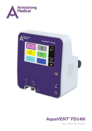
AquaVENT® FD140i User Manual, English
Guidance
Guidance WARNING Correct operation of this device is described in this User Manual and on other documents or materials enclosed or provided by the manufacturer. It should only be assembled, operated, maintained and repaired according to such information. The device must be checked prior to each clinical use to verify that it is operable and meets the user’s requirements for delivery of therapy to patients. The device must be inspected at regular intervals by a competent person. The device must not be used if found to be defective. A defective device must be removed to a location where it is not at risk from inadvertent clinical use. If a repair is necessary, the manufacturer and distributor recommend contacting the manufacturer or their authorised representative to arrange such works. Maintenance and repairs must only be carried out by the manufacturer or by competent persons authorised by the manufacturer to undertake such work. The user of the device shall have sole responsibility for any malfunction or damage which is due to improper use, poor maintenance, improper service, improper repairs or modifications carried out by unauthorised persons. The device is provided with a serial number located on an identification plate at the rear of the device. The identification plate specifies the manufacturer and their contact details, the device product code and the device serial number. After set-up of a breathing system and prior to connection of the breathing system to the patient, verify that: a. Gas flow is running in the breathing system. b. Separate inspiratory and expiratory gas paths are present and functioning. Serial number format
Example 1: 10190001 10190001 10190001 Example 2: 20200099 20200099 20200099
2
10190001 First “10” represents device with paramagnetic oxygen sensor option “19” represents 2019 (year of manufacture) Last “1” represents the 1st device manufactured 20200099 First “20” represents device with oxygen fuel cell option “20” represents 2020 (year of manufacture) Represents the 99th device manufactured
AquaVENT® FD140i, User Manual, English Issue 05
Contents
3
AquaVENT® FD140i, User Manual, English Issue 05
Contents
Contents Page No. 7 8 9 10 11 12 12 12 12
1. Introduction 1.1 1.2 1.3 1.4 1.5 1.6 1.7 1.8 1.9
About this manual Indications for use Contraindications Adverse effects General safety precautions Limitation of liability Copyright Service life Warranty
2. AquaVENT® FD140i overview 14 14-16 17 18-19
2.1 2.2 2.3 2.4
Principle of operation Device layout Therapy modes technical specification Device interface Front panel icons and indicator lights Touch screen icons
3. Device setup 21 21-22 23-24 25 25 25 26 26-32
3.1 Unpacking 3.2 Mounting 3.3 Power supply Connecting to mains supply Battery powered operation 3.4 Connecting to gas supply 3.5 Gas supply failure 3.6 Single gas operation 3.7 Breathing circuit set-up 3.8 Using a heater humidifier 4. Using the AquaVENT® FD140i
34 34 35 36 37 38 39 40
41 42-43 44 45 46-47 48 4
4.1 4.2 4.3 4.4 4.5 4.6 4.7 4.8
Powering on the device Powering off the device Automatic switch-OFF due to discharged battery Self check Oxygen sensor calibration Therapy selection menu Flow settings menu Alarm settings menu Patient pressure alarm settings Apnoea alarm settings F Max alarm settings 4.9 General settings menu 4.10 Therapy menu 4.11 Starting therapy 4.12 Stopping therapy 4.13 Use with a nebulising system 4.14 Touch screen unlock AquaVENT® FD140i, User Manual, English Issue 05
Contents
Page No. 50 50 51 51 52-53 54-57 57
5. Alarms and notifications 5.1 5.2 5.3 5.4 5.5 5.6 5.7
Alarm indicator button Alarm acknowledgement Muting alarm audio Alarm volume adjustment CPAP low pressure alarm flow settings override Alarm types Alarms settling period
6. Maintenance and repair 59 59
6.1 Repair 6.2 Servicing schedule 7. Cleaning and decontamination
61 61
7.1 Cleaning 7.2 Decontamination 8. Technical specifications
63-64 65 66 66 66 67 67-70
8.1 8.2 8.3 8.4 8.5 8.6 8.7
Technical specifications Therapy modes technical specification Parameter settings Measurement functions Paramagnetic oxygen sensor External communication Electromagnetic environment
9. European Community Declaration of Conformity 72
9.1 EC Declaration of Conformity 10. Disposal
74
10.1 Disposal 11. Appendices
76 77 78 79
11.1 Appendix 1 - Therapy Set-up flow diagram 11.2 Appendix 2 - Accessories 11.3 Appendix 3 - Definitions 11.4 Appendix 4 - User manual revision history Back Cover 1. 2.
5
Technical support and customer service details EU Authorised Representative
AquaVENT® FD140i, User Manual, English Issue 05
1 Introduction
6
AquaVENT® FD140i, User Manual, English Issue 05
Introduction
1.1 About this manual This User Manual describes the intended use of AquaVENT® FD140i with software version 1.01. AquaVENT® FD140i and accompanying User and Technical Manuals are available in English, French, German, Italian, Dutch and Spanish. To ensure safe operation of AquaVENT® FD140i, the device must only be used as described in this manual. Before using AquaVENT® FD140i, the full contents of this manual must be read and understood. The AquaVENT® FD140i must only be used by qualified healthcare professionals trained in the operation of the device. Armstrong Medical Ltd. reserves all rights to further develop and alter AquaVENT® FD140i in the interest of technical progress and patient safety.
AquaVENT® FD140i complies with Medical Devices Directive, provided it is operated according to the User Manual. “1639” is the identification number of the Notified Body.
WARNING
• •
Read the entire manual before using the AquaVENT® FD140i AquaVENT® FD140i is for use only by trained healthcare professionals and only within a healthcare facility
•
Use AquaVENT® FD140i only for the intended use as described in this manual.
7
AquaVENT® FD140i, User Manual, English Issue 05
Introduction
1.2 Indications for use AquaVENT® FD140i is a gas flow driver, delivering an air and oxygen mixture at 21-100%. It is a clinical respiratory therapy device which assists respiration using continuous positive airway pressure (CPAP) and high flow oxygen therapy (HFOT) in patients in a hospital setting. Such patients must be medicallyindicated by a healthcare professional for the respective therapy once assessed as conscious and breathing spontaneously and not at significant risk of conditions of exacerbation caused by the therapy or at risk of a prolonged apnoeic event. AquaVENT® FD140i is not a life-support device. Always verify that an expiratory gas path is present and functioning BEFORE commencing therapy on a patient. CPAP therapy can be applied in different modes and delivered using a suitable breathing circuit connected to a face mask, tracheal tube or tracheostomy tube or by helmet. In the case of BUBBLEPAP mode the circuit is connected to a nasal cannula. Furthermore, AquaVENT® FD140i can be used as a gas flow driver for High Flow Oxygen Therapy (HFOT) delivered via nasal cannula, face mask and tracheostomy tube. With the exception of CPAP Helmet therapy, we advise that all breathing circuits in use must be set-up to deliver the gas as heated and humidified. AquaVENT® FD140i is intended for use with adults, children and new-born babies should they be medically-indicated for the therapy and should the therapy be listed as suitable for that patient group. This device is not recommended for use in a domestic environment. AquaVENT® FD140i is equipped either with a paramagnetic oxygen sensor or a replaceable oxygen fuel cell. These sensors continuously measure O2 delivery to the breathing circuit. This value is displayed on the screen. To ensure that hypoxemic and hyperoxic gas mixtures are not inadvertently delivered to patients, we advise that O2 delivery is monitored at all times during therapy and that external peripheral oximetry is considered as an adjunct. The paramagnetic oxygen sensor is maintenance-free. It should be calibrated once annually or when the device has been moved or transported – such that vibration of the device as occurred. The replaceable oxygen fuel cell has a finite usable life-time based on volume of gas flow delivered to the breathing circuit. The device is equipped with an internal rechargeable battery with an integrated mains power failure alarm.
8
AquaVENT® FD140i, User Manual, English Issue 05
Introduction
1.3 Contraindications This section details some, but not all conditions, which make the following therapies inadvisable: CPAP • Respiratory arrest or unstable cardiorespiratory status • Reduced consciousness • Apnoea • Inability to protect airway • Extremely anxious patient • Facial trauma / burns • Facial, oesophageal, or gastric surgery • Low blood pressure secondary to blood loss • Stomach surgery or bowel bleeding Helmet CPAP Claustrophobic or tetraplegic patients Tidal volume monitoring requirement
• •
Paediatric CPAP Obstruction of sinonasal polyposis (SNP) from secretions Pulmonary interstitial emphysema Pneumomediastinum Pneumothorax Decreased cardiac output (due to decreased venous return) with excessive CPAP levels Inadequate ventilation Gastric distension or feed intolerance Increased work of breathing due to increased airway resistance (related to diameter of SNP)
• • • • • • • •
BUBBLE-PAP Obstruction of SNP Large emphysematous bullae Acute asthma or severe bronchospasm Lung abscess Severe fibrotic changes Increased work of breathing e.g. COPD or acute asthma Intracranial pressure >20mmHg Dialysis
• • • • • • • •
High Flow Oxygen Therapy (HFOT) Pneumothorax Acute bullous lung disease Low blood pressure Cerebrospinal fluid leak Cranial surgery / trauma
• • • • •
POINT Any contraindication to CPAP Reduced levels of consciousness Extremely anxious patient patients Epistaxis Facial injury Airway obstruction
• • • • • • 9
AquaVENT® FD140i, User Manual, English Issue 05
Introduction
1.4 Adverse effects The most common adverse effects during CPAP therapies are face mask or helmet or gas flow/pressure related. Some patients may experience claustrophobia due to the mask, nasal congestion, rhinitis or a runny nose. To minimise these adverse effects ensure that:
• • •
Correct face mask size is used – if the mask is too small / large it may result in discomfort and air leaks. Mask is not overtightened – may result in mask discomfort and damage to the skin. Heated humidified air is used via a heater humidifier.
Helmet CPAP is predisposed to CO2 rebreathing and could increase the patients’ ventilator asynchrony. In addition to the adverse effects stated above, Paediatric CPAP may result in congestion, dry mouth, lip bleeds or nosebleeds. Masks may cause irritation or redness of the skin. Using the correct mask size and padding can minimise pressure sores from tight contact with skin. BUBBLE-PAP may also cause nosebleeds; humidification can often help with these symptoms. Again, heated humidified air can help to prevent nosebleeds from occurring. Adverse effects when using HFOT can include skin irritation, skin breakdown and nasal dryness. It is important to be aware that HFOT can lead to suppression of breathing, oxygen toxicity and is a fire hazard at high oxygen concentrations.
10
AquaVENT® FD140i, User Manual, English Issue 05
Introduction
1.5 General safety precautions To ensure safe operation of AquaVENT® FD140i , all precautions contained within this chapter must be adhered to, in addition to all other warnings, cautions and notes dispersed throughout the User Manual. WARNING
Alerts you to a situation which may cause patient or user injury
CAUTION
Explains measures for the effective use of the device
NOTE
Refers to important information which should be taken into consideration by the user.
WARNING
•
AquaVENT® FD140i is for use only by trained healthcare professionals and only within a healthcare facility.
•
Patients receiving respiratory therapy should be closely monitored by a qualified healthcare professional, trained in the use of the device.
•
AquaVENT® FD140i is not intended to be operated by patients.
•
Electromagnetic interference may occur if the device is not used in accordance with this User Manual. AquaVENT® FD140i has been tested and complies with BS EN 60601-1-2:2015. Information on electromagnetic compatibility can be found under Section 8.7.
•
AquaVENT® FD140i must not be used in close proximity to nuclear magnetic resonance equipment. Devices in the vicinity of AquaVENT® FD140i, which generate electromagnetic fields, can affect the safe operation of the device and endanger the patient.
•
Mobile telephones and any portable RF communication equipment (including peripherals such as antenna cables and external antennas) should not be used within 30cm (12 inches) of any part of AquaVENT® FD140i. This can result in improper operation of the device.
•
AquaVENT® FD140i must not be used in the presence of flammable substances or in potentially explosive atmospheres.
•
AquaVENT® FD140i is designed for use only within the limits of the operating environment described in Section 8.1 Technical Specification. If the temperature of AquaVENT® FD140i is higher or lower than its specified operating range then wait 1-hour to allow the device to adjust to operating temperature prior to use.
•
AquaVENT® FD140i should not be positioned such that the cooling fan outlet is obstructed.
•
AquaVENT® FD140i must always be disconnected from mains power before any cleaning, maintenance or repair.
•
Use of this equipment, adjacent to, or stacked with other equipment should be avoided as it could result in improper operation. If such use is necessary, this equipment should be observed to verify that they are operating normally. Device setup has been described in Section 3 of this manual.
11
AquaVENT® FD140i, User Manual, English Issue 05
Introduction
CAUTION
•
Use of other electrical equipment with AquaVENT® FD140i or in its vicinity should be avoided, as it can result in improper operation. If such use is necessary, AquaVENT® FD140i and other equipment must be verified prior to connecting the patient to AquaVENT® FD140i. NOTE
•
The emissions characteristics of this equipment make it suitable for use in industrial areas and hospitals (CISPR 11 class A). If it is used in a residential environment (for which CISPR 11 class B is normally required) this equipment might not offer adequate protection from radio-frequency communication services. The user might need to take mitigation measures, such as relocating or re- orienting the equipment.
1.6 Limitation of liability The manufacturer shall not accept any liability for damages due to:
• • • • •
Failure to adhere to this User Manual Use of device by untrained personnel Improper use / maintenance Unapproved modifications to the device Use of unapproved spare parts
1.7 Copyright This User Manual may only be copied, photocopied, reproduced or translated in to other languages for personal use. Reproduction for disclosure to third parties is not permitted without prior written consent from Armstrong Medical Ltd.
1.8 Service life When the device is used correctly and in-line with this User Manual, the expected service life of AquaVENT® FD140i is 10 years from the date of delivery to the hospital.
1.9 Warranty The warranty conditions correspond with Armstrong Medical’s terms and conditions at the time of purchase. Warranty will be valid for 2-years from the date of delivery to the hospital and will cover defects in parts and labour that arise when the repaired device is used correctly and in-line with this User Manual.
12
AquaVENT® FD140i, User Manual, English Issue 05
AquaVENT® FD140i Overview
2 AquaVENT® FD140i Overview
13
AquaVENT® FD140i, User Manual, English Issue 05
AquaVENT® FD140i Overview
2.1 Principle of operation AquaVENT® FD140i is an electronic gas flow driver which delivers an adjustable blend of medical air and oxygen to the patient via an attached breathing circuit. The device has six preset respiratory therapies;
• • • • • •
CPAP CPAP Paed CPAP Helmet BUBBLE-PAP HFOT POINT®
For a description of each therapy please refer to Section 3.7 “Breathing circuit setup”. Each mode has customized settings according to the therapy characteristics. The device is also equipped with a nebuliser outlet port which supplies a flow of medical air for driving a jet nebuliser containing liquid drug suspension. AquaVENT® FD140i incorporates a user friendly touch screen interface facilitating intuitive operation. Its sophisticated alarm system and advanced oxygen sensing technology collaborate to safeguard patient care. Additionally, the device is equipped with an internal Li-Ion battery for uninterrupted operation in the event of a temporary disconnection from the mains supply.
2.2
Device layout
4
5
6 7 8 1 14
2
3 AquaVENT® FD140i, User Manual, English Issue 05
AquaVENT® FD140i Overview
9 10
11
12
13 14 15 16 17
15
AquaVENT® FD140i, User Manual, English Issue 05
AquaVENT® FD140i Overview
2.2 Device layout
18
19
16
Item
Description
1
Pressure measurement port
2
Respiratory gas outlet
3
Nebuliser port
4
Touch screen
5
Alarm mute button
6
Mains power connection indicator
7
Battery status indicator
8
Power on/off button
9
Refer to instruction manual/booklet
10
Mains power inlet
11
USB connector
12
Handle
13
Fan outlet
14
Fixation claw
15
Serial plate
16
Medical Oxygen inlet
17
Medical Air inlet
18
Over pressure relief valve
19
Anti-asphyxiation entrainment valve
AquaVENT® FD140i, User Manual, English Issue 05
AquaVENT® FD140i Overview
2.3 Therapy modes technical specification
Mode Interface screen colour
CPAP
CPAP (Paed)
Helmet CPAP
BUBBLEPAP
HFOT
POINT
Purple
Grey
Yellow
Green
Light blue
Dark blue
Flow range (L/min)
20-140
10-70
40-140
2-20
2-70
10-80
Default flow (L/min)
60
20
60
5
20
30
Oxygen range (%)
21-100
21-100
21-100
21-80
21-100
21-100
Default oxygen (%)
30
30
30
30
30
60
Pressure measured
Yes
Yes
Yes
Yes
No
No
Breath frequency measured
Yes
Yes
Yes
No
No
No
Nebuliser ON
Yes
Yes
No
No
Yes
Yes
Pressure alarm range (cmH2O)
2-25 and OFF
2-25 and OFF
2-25 and OFF
2-15 and OFF
-
-
Default pressure alarm ‘Low’
2
2
2
2
-
-
Default pressure alarm ‘High’
12
12
12
10
-
-
Apnoea alarm range (sec)
20-60
20-60
20-60
-
-
-
20
20
20
-
-
-
Default apnoea alarm period (sec)
17
AquaVENT® FD140i, User Manual, English Issue 05
AquaVENT® FD140i Overview
2.4 Device interface Front panel icons and indicator lights Description 1. Power source indicators AC mains power supply is connected when indicator light is illuminated Running on internal battery when indicator light is illuminated solid green Internal battery is charging when indicator light is flashing green Internal battery level is ≤ 20% charged when indicator light is illuminated solid red 2. Power on or off device Power on or off device 3. Alarm mute Alarm audio is muted when indicator light is flashing orange Alarm audio is sounding when indicator light is solid orange 4. Gas ports Respiratory gas outlet Patient pressure measurement connection Nebuliser port
18
AquaVENT® FD140i, User Manual, English Issue 05
AquaVENT® FD140i Overview
Touch screen icons Description 1. Screen lock Screen Locked 2. Power supply and battery charge indication Device unplugged from mains power ...%
Internal battery level-percentage charged (alternates between battery icon and unplugged icon) Battery level at 20% or below Battery charging
Charging
3. General settings General Settings Menu
Screen brightness
Return to previous menu
Language selection
Touch tone volume Alarm volume 4. Therapy settings Adjust flow settings
Therapy timer
Adjust alarm settings
Start therapy
Select approximate value
Stop therapy
Increase value incrementally
Nebuliser gas supply off
Decrease value incrementally
Nebuliser gas supply on
Minimum permissible value
Respiratory gas values
Maximum permissible value
In therapy icon
5. Alarms Warning - alarm activated Alarm silenced
19
AquaVENT® FD140i, User Manual, English Issue 05
Device Setup
3 Device Setup
20
AquaVENT® FD140i, User Manual, English Issue 05