Service Manual
290 Pages
Preview
Page 1
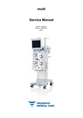
multi Service Manual Edition: 3A-2015 Part no.: M56 970 1 0123
Table of contents 1
Index
2
Important information
3
4
2.1
How to use the Service Manual... 2-1
2.2
Significance of warnings ... 2-2
2.3
Significance of notes ... 2-2
2.4
Significance of tips... 2-2
2.5
Considerations for working on the device... 2-3
2.6 2.6.1
Warnings ... 2-4 Warnings, electrical ... 2-4
2.7
Addresses ... 2-5
Installation 3.1
Installation / initial start-up requirements ... 3-1
3.2
Accessories required for performing the installation / initial start-up... 3-1
3.3 3.3.1 3.3.2 3.3.3 3.3.4
Initial start-up... 3-2 Important information on initial start-up ... 3-2 Electrical installation ... 3-2 Initial start-up report... 3-3 Explanatory notes for completing the initial start-up report ... 3-8
3.4 3.4.1 3.4.2 3.4.3 3.4.4
Transport / storage... 3-25 Device relocation, multiFiltratePRO version ... 3-25 Device relocation, multiPheresis version... 3-27 Transport ... 3-28 Storage ... 3-28
3.5 3.5.1 3.5.2
Environmental compatibility / disposal ... 3-29 Information for the responsible organization ... 3-29 Information for recycling and waste disposal facilities... 3-29
Specifications 4.1 4.1.1 4.1.2
Dimensions and weight ... 4-1 multiFiltratePRO ... 4-1 multiPheresis ... 4-1
4.2 4.2.1
Identification label (device marking) ... 4-1 Identification label of the device ... 4-1
Fresenius Medical Care
multi
SM-EN
3A-2015
3
5
4.2.2
4.2.1.1 multiFiltratePRO ... 4-1 4.2.1.2 multiPheresis... 4-2 Power label... 4-3
4.3
Electrical safety ... 4-3
4.4
Electric power supply ... 4-4
4.5 4.5.1 4.5.2 4.5.3
EMC guidance and manufacturer’s declaration ... 4-5 Electromagnetic emissions... 4-5 Electromagnetic immunity ... 4-5 Recommended separation distances between portable and mobile RF communications equipment and the multi device (multiFiltratePRO or multiPheresis) ... 4-7
4.6
Operating conditions ... 4-9
4.7
External connection options ... 4-9
4.8 4.8.1 4.8.2
Operating programs ... 4-10 multiFiltratePRO ... 4-10 multiPheresis ... 4-11
4.9 4.9.1 4.9.2
Extracorporeal blood circuit and safety systems ... 4-12 multiFiltratePRO ... 4-12 multiPheresis ... 4-14
4.10 4.10.1 4.10.2
Extracorporeal blood circuit and safety systems ... 4-15 multiFiltratePRO ... 4-15 multiPheresis ... 4-19
4.11
Materials used... 4-23
Setup / service program 5.1 5.1.1
System parameters ... 5-1 System parameter settings... 5-1 5.1.1.1 Pressure selection... 5-2 5.1.1.3 Applications ... 5-3
5.2 5.2.1 5.2.2 5.2.3 5.2.4 5.2.5
User setup ... 5-6 Accessing the User setup... 5-6 Heparin ... 5-8 User interface ... 5-9 Enable treatment options... 5-10 TA settings... 5-11 5.2.5.1 TA pressure alarm limits... 5-11 5.2.5.2 Plasma Adsorb anticoagulation... 5-12 5.2.5.3 Plasma Adsorb treatment parameters... 5-13 CRRT settings ... 5-15 5.2.6.4 Treatment parameters, adult ... 5-19
5.2.6 5.3 5.3.1 5.3.2
Miscellaneous ... 5-25 Factory settings ... 5-25 Information page... 5-26
5.4
Service setup ... 5-27
5.5 5.5.1
Access in the event of an error condition... 5-27 Enabling access ... 5-27
Fresenius Medical Care
multi
SM-EN
3A-2015
4
6
Technical Safety Checks / maintenance procedures 6.1
Important information on TSC / MA ... 6-1
6.2
Accessories required for performing the TSC / MA ... 6-2
6.3
TSC / MA report ... 6-2
6.4
Explanatory notes for completing the TSC / MA report ... 6-7
7
Error messages
8
Test equipment and accessories
9
Calibration / adjustment 9.1 9.1.1 9.1.2 9.1.3 9.1.4 9.1.5 9.1.6 9.1.7 9.1.8 9.1.9 9.1.10 9.1.11 9.1.12 9.1.13 9.1.14 9.1.15 9.1.16 9.1.17 9.1.18
Accessing the Service setup... 9-1 Diagnostics / Calibration... 9-3 Calibrate screen ... 9-3 Scales... 9-5 BLD1... 9-6 Voltages... 9-7 Pressure PS1-PS4 ... 9-7 Pressure PS5-PS8 ... 9-8 Pumps ... 9-9 Ejectors... 9-10 Pump doors ... 9-10 Clamps ... 9-11 Heaters ... 9-12 Heparin ... 9-13 Ci-Ca ... 9-13 Cassette detector ... 9-14 ABD / OD / LD ... 9-15 Pneumatics... 9-16 Miscellaneous... 9-17
9.2 9.2.1 9.2.2
Setup... 9-18 Device settings ... 9-19 Network settings ... 9-20
9.3
Module status ... 9-21
9.4
System parameters ... 9-23
9.5
Update ... 9-23
9.6
Event memory... 9-24
10 Servicing/repairs 10.1
Important information on servicing/repairs ... 10-1
Fresenius Medical Care
multi
SM-EN
3A-2015
5
10.2 10.2.1 10.2.2 10.2.3 10.2.4 10.2.5 10.2.6 10.2.7 10.2.8
Component overview ... 10-2 Extracorporeal blood circuit module and side panel on right... 10-2 Monitor... 10-4 Electronics box, exterior ... 10-5 Electronics box, interior, inside of door... 10-6 Electronics box, interior ... 10-7 Side panel on left (CRRT) ... 10-8 Side panel on right (CRRT) ... 10-9 Extracorporeal Blood Circuit Module (CRRT), open View 1... 10-10 10.2.9 Extracorporeal Blood Circuit Module (CRRT), open View 2... 10-11 10.2.10 Upper scale assembly ... 10-12 10.2.11 Lower scale assembly ... 10-13 10.3 10.3.1
Component assembly ... 10-14 Self-tapping screws ... 10-14
10.4 10.4.1 10.4.2 10.4.3
Preparations for working on the device ... 10-15 Removing the rear panel ... 10-15 Opening the extracorporeal blood circuit module ... 10-19 Closing the extracorporeal blood circuit module... 10-21
10.5 10.5.1 10.5.2
Housing and trolley ... 10-22 Seals... 10-22 10.5.1.1 Replacing the left side panel seal... 10-22 10.5.1.3 Replacing the front panel seal... 10-23 Replacing a trolley wheel... 10-25
10.6 10.6.1 10.6.2
Monitor ... 10-27 Replacing the monitor arm ... 10-27 Replacing the seal of the monitor ... 10-29
10.7 10.7.1 10.7.2 10.7.3 10.7.4 10.7.5 10.7.6 10.7.7 10.7.8 10.7.9 10.7.10 10.7.11 10.7.12 10.7.13 10.7.14 10.7.15
Extracorporeal Blood Circuit Module (EBM)... 10-31 Replacing the cassette detector ... 10-31 Replacing a line occlusion clamp ... 10-31 Replacing a pressure measurement unit... 10-34 Replacing the pressure transducer of the return line... 10-37 Replacing the level detector ... 10-38 Replacing a pump motor ... 10-39 Replacing a pump sensor... 10-41 Replacing a pump stator... 10-42 Replacing an ejector unit ... 10-43 Replacing the pneumatic tube ... 10-44 Replacing the compressor unit ... 10-45 Replacing the valve block (CRRT) ... 10-46 Replacing the optical detector (OD) / air bubble detector (ABD)... 10-48 Replacing the Ci-Ca pump drives... 10-48 Replacing the Ci-Ca drip counters... 10-49
10.8 10.8.1 10.8.2 10.8.3 10.8.4
Side panel on left (CRRT) ... 10-50 Opening the side panel with the heaters ... 10-50 Closing the side panel with the heaters... 10-50 Replacing the side panel with the heaters... 10-50 Replacing the heater units... 10-53
10.9 10.9.1 10.9.2
Side panel on right (CRRT)... 10-55 Opening the side panel with the heparin pump ... 10-55 Closing the side panel with the heparin pump... 10-56
Fresenius Medical Care
multi
SM-EN
3A-2015
6
10.9.3 10.9.4 10.9.5 10.9.6
Replacing the side panel and heparin pump ... 10-57 Replacing the heparin pump... 10-58 Replacing the syringe detector of the heparin pump ... 10-59 Replacing the filter holder... 10-61
10.10 Scales ... 10-61 10.10.1 Replacing the upper scale assembly... 10-61 10.10.2 Replacing the lower scale assembly ... 10-62 10.11 PSU and battery pack... 10-64 10.11.1 Replacing the PSU ... 10-64 10.11.2 Replacing the battery pack ... 10-66 10.12 Printed circuit boards ... 10-67 10.12.1 PCB LP 1104 Monitor power supply board ... 10-67 10.12.2 PCB LP 1131 Monitor operating mode indicator ... 10-70 10.12.3 PCB LP 1134 Monitor card reader ... 10-71 10.12.4 PCB LP 1145-1 Monitor distribution board ... 10-72 10.12.5 PCB LP 1150 Screen failure sensor... 10-74 10.12.6 PCB LP 1202 Controller board (C167) ... 10-75 10.12.7 PC board ... 10-77 10.12.8 PCB LP 1226 Mainboard... 10-79 10.12.9 PCB LP 1227 Communication board... 10-84 10.12.10 PCB LP 1228 Power distribution board ... 10-89 10.12.11 PCB LP 1231 Interface board... 10-92 10.12.12 PCB LP 1235 Heparin pump control board ... 10-95 10.12.13 PCB LP 1355 C167 board ... 10-97 10.12.14 PCB LP 122 Heater control board ... 10-100
11 Functional description 11.1 11.1.1 11.1.2 11.1.3
Overview of PCBs... 11-1 Monitor... 11-1 Electronics box ... 11-2 Extracorporeal Blood Circuit Module ... 11-3
11.2
Monitor ... 11-4
11.3
Electronics box... 11-6
11.4
Extracorporeal Blood Circuit Module ... 11-7
11.5
Pneumatics ... 11-8
12 Appendix
Fresenius Medical Care
multi
SM-EN
3A-2015
7
8
Fresenius Medical Care
multi
SM-EN
3A-2015
Fresenius Medical Care
multi
SM-EN
3A-2015
9
10
Fresenius Medical Care
multi
SM-EN
3A-2015
Chapter 1: Index
1
Index
A
End of treatment / reinfusion 4-11
N
Access pressure 4-15, 4-19
Environmental compatibility / disposal 3-29
Note symbol, significance 2-2
Accessories required for performing the TSC / MA 6-2
Error messages 7-1 Explanatory notes for completing the initial start-up report 3-8
Addresses 2-5 Air bubble detector 4-17, 4-20 Ambient temperature sensor 4-13, 4-14 Appendix 12-1
Explanatory notes for completing the TSC / MA report 6-7
O Operating programs 4-10 Optical detector 4-16, 4-20 Overview of PCBs 11-1
External connection options 4-9 Extracorporeal blood circuit and safety systems 4-15
P
B
F
Pre-filter pressure 4-15, 4-19
Balancing error 4-13
Fill level detector 4-16, 4-20
Audible signal 4-18, 4-21
Batteries – PC board 10-78
Filling 4-10, 4-11 Flow rates 4-12, 4-14
Battery 3-29
Functional description 11-1
Blood leak/hemolysis detector 4-12, 4-14
Functional test 4-10, 4-11 Fuses – PCB LP1104 10-68 – PCB LP122 10-101 – PCB LP1226 10-81 – PCB LP1227 10-88 – PCB LP1228 10-90 – PCB LP1235 10-96
Blood pump 4-16, 4-20
C Calcium pump 4-22 Calibration / adjustment 9-1 Cassette detector 4-18 Ci-Ca drip counter 4-18, 4-21 Ci-Ca fill level detector 4-18, 4-22 Circulation 4-10 Citrate pump 4-22 Compatibility matrix – display 10-73 Connection options 4-9 Considerations for working on the device 2-3
D Dimensions 4-1
E Electrical safety 4-3 Electromagnetic emissions 4-5 Electromagnetic immunity 4-5
Fresenius Medical Care
multi
H Heater microswitch 4-14
Patient connection 4-10, 4-11 Preparation 4-10, 4-11 Printed circuit boards – PC board 10-77 – PCB LP1104 10-67 – PCB LP1131 10-70 – PCB LP1134 10-71 – PCB LP1145-1 10-72 – PCB LP1150 10-74 – PCB LP1202 10-75 – PCB LP122 10-100 – PCB LP1226 10-79 – PCB LP1227 10-84 – PCB LP1228 10-89 – PCB LP1231 10-92 – PCB LP1235 10-95 – PCB LP1355 10-97
Heparin pump 4-17, 4-21
R
How to use the Service Manual 2-1
Reinfusion 4-11
I
Rinsing 4-10, 4-11
Important information 2-1 Important information on initial start-up 3-2
Return pressure 4-15, 4-19
S Scale system 4-13, 4-14
Important information on TSC / MA 6-1
Servicing/repairs 10-1
Initial start-up report 3-3
Setup / service program 5-1
Installation 3-1
Specifications 4-1 Storage 3-28
M
Storage conditions 3-29
Materials 4-23
SM-EN
Self-tapping screws 10-14
3A-2015
System parameters 4-11
1-1
Chapter 1: Index
T Technical Safety Checks / maintenance procedures 6-1 Test equipment and accessories 8-1 Tip symbol, significance 2-2 TMP 4-16, 4-19 Transport 3-28 Treatment 4-10, 4-11 Treatment pause 4-11 TSC / MA report 6-2
U Ultrafiltration 4-12
W Warning symbol, significance 2-2 Warnings 2-4 Weight 4-1
Fresenius Medical Care
multi
SM-EN
3A-2015
1-2
Chapter 2: Important information
2
Important information
2.1
How to use the Service Manual Purpose
This document is intended for service technicians and is to be used for initial study (to acquire a basic knowledge) and for reference purposes (for Technical Service Checks, maintenance procedures and repairs). The document does not replace the training courses offered by the manufacturer.
Identification
The document can be identified by the following information on the title page and on the labels, if any: – Document edition – Document part number
Footer
The footer contains the following information: – Company name – Device type – The English abbreviation for the document type and the international abbreviation for the document language, e.g., SM-EN means Service Manual in English. – The edition identification, e.g., 4A-2013 refers to edition 4A released in 2013. – The page identification, e.g., 1-3 refers to chapter 1, page 3
Organization of the chapters
To facilitate the use of documents from Fresenius Medical Care, the organization of the chapters has been standardized in all manuals. There may therefore be chapters within this document without any content. Chapters without content are marked accordingly.
Styles used in the document
The following text styles may be used in the document: Style
Description
Keys and buttons
Keys and buttons on the device are shown in bold type. Example: User setup button.
Message text
Messages displayed by the device are shown in italic type. Example: Message: Prepare for starting zero adjustment of scale.
Instructions
Instructions are indicated by an arrow . Instructions must be followed. Example: Press the appropriate key to select the area you require.
Illustrations
Fresenius Medical Care
The illustrations used in the documents may differ from the original if this does not have any influence on the function.
multi
SM-EN
3A-2015
2-1
Chapter 2: Important information
2.2
Changes
Changes to documents will be released as new editions or supplements. In general, this manual is subject to change without notice.
Reproduction
Reproduction, even in part, is only permitted with written approval.
Significance of warnings Warning Advises the operator that failure to observe this information can result in personal injury.
2.3
Significance of notes Note Advises the operator that failure to observe this information can result in the following: – damage to the device – required functions will not be executed at all or not executed correctly
2.4
Significance of tips Tip Information providing useful tips for easy handling.
2-2
Fresenius Medical Care
multi
SM-EN
3A-2015
Chapter 2: Important information
2.5
Considerations for working on the device Requirements
The technician must be familiar with the latest Instructions for Use of the device. The technician must have experience in mechanical engineering, electrical engineering, and medical technology.
Authorized persons
Start-up, extensions, adjustments, calibrations, maintenance procedures, modifications or repairs must only be carried out by the manufacturer or persons authorized by the manufacturer.
Test equipment and accessories
The activities described in this document assume that the necessary technical test equipment and accessories are available.
Specifications
The information contained in the Specifications chapter of the latest Instructions for Use must be observed.
Precautions
Repair any visible damage before switching the device on. Before opening the device and when working on the open device, the following precautions must be observed: – Protect the components against exposure to liquids. – Do not touch live parts. – Plugs, connections and components must only be disconnected or connected when not under power.
ESD precautions
When repairing the device and replacing spare parts, observe the relevant ESD safety measures.
After working on the device
After work has been carried out on the device, a T1 test and an electrical safety check (see Chapter 6 on page 6-1) must be performed. Check that the current Instructions for Use are readily available at the point of operation of the device. Ensure the user is given the necessary additional instructions on any changes made.
Spare parts
Use only original spare parts. For identifying and ordering spare parts, test equipment and tools, always use the electronic spare parts catalog.
Fresenius Medical Care
multi
SM-EN
3A-2015
2-3
Chapter 2: Important information
2.6
Warnings
2.6.1
Warnings, electrical
Warning Risk of injury through electrical voltage. Touching live parts will cause an electric shock. Unplug the power cable before opening the device. Simply using the On / Off button to switch off the device does not disconnect the device from the supply voltage!
2-4
Fresenius Medical Care
multi
SM-EN
3A-2015
Chapter 2: Important information
2.7
Addresses Manufacturer
Fresenius Medical Care AG & Co. KGaA 61346 Bad Homburg Germany Phone: +49 (0)6172 609-0 www.fmc-ag.com
International service support
Fresenius Medical Care Deutschland GmbH Service Support International Hafenstrasse 9 97424 Schweinfurt Germany Phone: +49 (0)9721 678-333 (hotline) Fax: +49 (0)9721 678-130
Local service support
Fresenius Medical Care
multi
SM-EN
3A-2015
2-5
Chapter 2: Important information
2-6
Fresenius Medical Care
multi
SM-EN
3A-2015
Chapter 3: Installation
3
Installation
3.1
Installation / initial start-up requirements Note In order to minimize the risk of using incorrect citrate or calcium containers, it is advisable to have only one container of each type (one size and one concentration in each case) available throughout the entire hospital or dialysis center. The same citrate and calcium container settings must be made in the Setup menu option of all the devices in the same hospital or dialysis center. After bringing the device from a cooler room into a warmer room, allow approximately 2 hours for the system to adjust to the ambient temperature before switching it on. Charging the built-in battery
On receipt of the device, charge the battery as follows: Use the power cable to connect the device to the power supply. Switch the power switch of the device to "on". Leave the power switch of the device on for 10 hours.
3.2
Accessories required for performing the installation / initial start-up
Item
Description
Patient leakage current measurement kit
For the electrical safety checks of the TSC.
Tubing system for patient leakage current measurement kit
For the electrical safety checks of the TSC.
Start-up tubing system
Test equipment for components of the extracorporeal blood circuit.
Fresenius Medical Care
multi
SM-EN
3A-2015
3-1
Chapter 3: Installation
3.3
Initial start-up
3.3.1
Important information on initial start-up Considerations for working on the device
Read the information under "Considerations for working on the device" (see Chapter 2.5 on page 2-3).
Information on installation
The installation information contained in the latest Instructions for Use must be observed.
Environmental conditions
Variations in temperature during transport may cause water condensation on electrical parts. In the event of major variations in temperature, allow sufficient time for the device to adjust to the ambient temperature before start-up.
Qualification requirements of testers
The checks may only be performed by the manufacturer's service support organization or a person authorized by the manufacturer. The specified checks may only be performed by personnel qualified to perform them correctly based on their education, training, knowledge and experience. Furthermore, the persons performing the checks must be permitted to do so independently and without outside interference.
Technical Safety Checks (TSC)
The first TSC is required before the end of the 30th month following initial start-up after delivery from the factory. All further TSCs are required before the end of the 24th month following the last TSC performed. The completion of the TSCs must be entered in the Medical Device Register.
Maintenance procedures (MA)
3.3.2
The maintenance procedures (MA) are a recommendation of the manufacturer. The maintenance procedures help ensure trouble-free operation, and must be carried out for the first time before the end of the 30th month following initial start-up after delivery from the factory. All further maintenance procedures should be performed before the end of the 24th month following the last maintenance procedure performed.
Electrical installation
Warning The "type of protection against electric shock" for this device is "Protection class I". To avoid the risk of electric shocks, the device must only be connected to a power supply network with a protective earth. It must be taken into consideration that in many countries specific regulations of the national authorities are in force. Power supply connection
3-2
The national standards and regulations must be observed when connecting the device to the power supply network.
Fresenius Medical Care
multi
SM-EN
3A-2015
Chapter 3: Installation
3.3.3
Electromagnetic compatibility (EMC)
Please observe the following during installation and initial start-up: (see Chapter 4.5 on page 4-5)
Protective earth
For safety class I devices, the quality of the protective earth conductor of the installation is of particular importance. It must be taken into consideration that in many countries specific regulations of the national authorities are in force.
Power cable
If the power cable needs to be replaced, use only the original power cable listed in the spare parts catalog. The use of additional power strips and extension cables is prohibited.
Bonding connection (equipotential bonding)
Using the original accessory, connect the equipotential bonding conductor to the rear of the machine if this is required by law or for special applications at the place of installation.
Leakage currents
If additional equipment not listed in the Accessories chapter is connected to the device, there is a danger that the permitted leakage currents will be exceeded.
Initial start-up report Explanatory notes for completing the report
Fresenius Medical Care
multi
The explanatory notes for completing the report are in a separate chapter (see Chapter 3.3.4 on page 3-8).
SM-EN
3A-2015
3-3