ARTISTIC HEALTHCARE SEATING PTY LTD
Agilia Volumetric Infusion Pumps
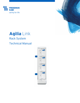
Agilia Link Rack System Technical Manual June 2019
Technical Manual
116 Pages
Preview
Page 1
Agilia Link Rack System Technical Manual
Symbols Description Device identification label
Packaging symbols
General warning sign
Fragile, handle with care
Refer to the Instructions For Use
This way up
Operating instructions
Keep away from rain
Product reference / part number
Temperature limitation
Product serial number
Humidity limitation
IN
Input terminal - connector
Atmospheric pressure limitation
OUT
Output terminal - connector
General symbol for recyclable material
Electrical fuses
Eco packaging symbol
Alternating Current (AC)
IP22
Other symbols
Index of protection against solid foreign objects (>12.5 mm) and dripping liquids Located on the back of the device Warning: Clamps must be mounted outside this area Protection against leakage current; type B applied part Not for use in residential areas
Located on the back of the device Warning! (refer to the Instructions For Use)
Part included in a recycling process
Located on the lock / release mechanism lever Press to lock and unlock Agilia pumps from the Agilia Link
Name and address of the manufacturing facility
Located near the functional earth terminal connection Functional earth terminal symbol
Name and address of the manufacturer / Date of manufacture (Year-Month-Day)
Located near the power connection Power status indicator
For US/CA only. Prescription statement: Caution: Federal law restricts this device to sale by or on the order of a physician (See 21 CFR 801.109(b)(1))
Located on the right and left sides of the device. Warning: Do not remove the Agilia Link from pole or rails if Agilia pumps are connected.
The Agilia Link is heavy when installed with Agilia pumps.
Remove Agilia pumps first, before removing the For CA only. CCSAUS mark
Agilia Link from poles or rails.
Unscrew lower pole clamp first. Unplug the power cord before cleaning. Do not spray liquids directly on the power supply connector.
On the back of the device, the Unique Device Identification label (UDI) is represented in AIDC (Automatic Identification and Data Capture) and readable text: (01) Product Identifier GTIN (21) Product Serial Number (11) Date of Manufacturer (240) Product Reference WARNING Warning of a potential hazard that could result in serious personal injury and/or product damage if the written instructions are not followed INFORMATION Recommendations to be followed.
10912-4_TM_Agilia_Link_ENG-US
Table of Contents 1
INTRODUCTION 1.1
2
1.2
INTENDED USE ... 6 INTENDED USERS... 6
1.4
INTENDED PATIENTS ... 6
1.5
OPERATION MODE ... 6
1.6
OPERATING SAFETY ... 7
1.7
CONTRA-INDICATIONS ... 7
1.8
USE ENVIRONMENT ... 7
AGILIA CONNECT INFUSION SYSTEM
5
8
AGILIA CONNECT INFUSION SYSTEM ... 8
INSTALLATION AND REMOVAL 3.1
4
SCOPE ... 6
1.3
2.1 3
6
9
PACKAGING CONTENT ... 9
3.2
AGILIA LINK PREPARATION ... 9
3.3
AGILIA LINK INSTALLATION ... 10
3.4
AGILIA PUMP INSTALLATION AND REMOVAL ... 12
3.5
REMOVE AGILIA LINK FROM FIXED POLE OR FIXED RAILS ... 13
SAFETY AND PRECAUTIONS
15
4.1
SAFETY RECOMMENDATIONS ... 15
4.2
WARNING AND PRECAUTIONS TO BE TAKEN ... 15
4.3
POWER MANAGEMENT ... 15
DESCRIPTION AND OPERATION
17
5.1
DEVICE DESCRIPTION ... 17
5.2
OPERATIONAL DESCRIPTION ... 20
6
TROUBLESHOOTING
21
7
INTERVENTION PROCEDURES
22
7.1
PROCEDURE #1: FIXING NUT ... 23
7.2
PROCEDURE #2: CAP SUPPORT ... 24
7.3
PROCEDURE #3: FRONT PANEL ... 26
7.4
PROCEDURE #4: LOWER HOUSING ... 32
7.5
PROCEDURE #5: POWER BOARD ... 38
7.6
PROCEDURE #6: AC POWER SUPPLY SWITCHES... 42
7.7
PROCEDURE #7: HOOK AND HOOK COVER ... 48
7.8
PROCEDURE #8: CHANGING THE LABELS ... 54
3
8
CLEANING AND DISINFECTION 8.1
9
55
RECOMMENDED AND PROHIBITED AGENTS ... 55
8.2
CLEAN THE AGILIA LINK AT PATIENT BEDSIDE ... 55
8.3
INSTRUCTIONS FOR CLEANING AND DISINFECTING ... 56
8.4
CLEANING AND DISINFECTION INSTRUCTIONS FOR ACCESSORIES ... 58
8.5
CLEANING AND DISINFECTION INSTRUCTIONS FOR AGILIA PUMPS ... 58
DEVICE STORAGE AND TRANSPORT 9.1
59
PRECAUTIONS FOR STORAGE ... 59
9.2
STORAGE AND TRANSPORT CONDITIONS ... 59
9.3
PREPARING THE AGILIA LINK FOR STORAGE ... 59
9.4
USING THE AGILIA LINK AFTER STORAGE ... 59
10 TECHNICAL SPECIFICATIONS
60
10.1
COMPLIANCE WITH STANDARDS ... 60
10.2
Technical data ... 60
10.3
MATERIAL CHARACTERISTICS ... 62
11 RECYCLING AND DISPOSAL
63
12 WARRANTY
64
12.1
GENERAL CONDITIONS OF WARRANTY ... 64
12.2
LIMITED WARRANTY ... 64
12.3
WARRANTY CONDITIONS FOR ACCESSORIES ... 64
13 SERVICING
65
13.1
SERVICE POLICY AND RULES... 65
13.2
MAINTENANCE REQUIREMENTS ... 65
13.3
TRAINING ... 65
13.4
MAINTENANCE SCHEDULE ... 66
13.5
CHECKS ... 67
14 GUIDANCE AND MANUFACTURER'S DECLARATION ON EMC
70
14.1
ELECTROMAGNETIC COMPATIBILITY ... 70
14.2
ELECTROSTATIC DISCHARGE (ESD) ... 70
14.3
ELECTROMAGNETIC COMPATIBILITY AND INTERFERENCE GUIDANCE ... 71
14.4
TABLE 1 - GUIDANCE AND MANUFACTURER'S DECLARATION - ELECTROMAGNETIC EMISSIONS ... 72
14.5
TABLE 2 - GUIDANCE AND MANUFACTURER'S DECLARATION - ELECTROMAGNETIC IMMUNITY ... 72
14.6
TABLE 4 - GUIDANCE AND MANUFACTURER'S DECLARATION - ELECTROMAGNETIC IMMUNITY ... 73
15 SPARE PARTS CATALOG
74
4
16 ORDERING INFORMATION
75
16.1
AGILIA LINK PACKAGING ... 75
16.2
POWER CABLES ... 75
16.3
FUNCTIONAL EARTH CABLE ... 75
16.4
INSTRUCTIONS FOR USE ... 75
16.5
QUICK REFERENCE GUIDES ... 75
16.6
OTHER ACCESSORIES ... 75
17 GLOSSARY OF TERMS
76
5
1
Introduction
The Agilia Link rack system is intended to power 4, 6 or 8 Agilia pumps connected to it. It reduces the number of power cords and improves infusion pump organization at bedside. This is a reusable device that is capable of continuous operation and that can be used daily. The use of Agilia Link does NOT change the standalone pump behavior.
1.1 Scope This Technical manual is applicable to the Agilia Link rack with the functional earth terminal, hereafter referred to as "device" or "Rack". Agilia Link exists in 3 types:
Agilia Link 4, Agilia Link 6, Agilia Link 8. Check that this document is applicable to the Agilia Link you are using. The user must adhere to the instructions specified in this document. Failure to adhere to these instructions may result in damages to the equipment, injuries to patients or injuries to users. Before using the Agilia Link rack system, read all accompanying documents provided with Agilia Link, Agilia pumps and accessories. Information within this document shall be completed by the ones of the IFU. Make sure to have fully understood how to use the device in order to ensure your safety and the safety of the patient.Pay particular attention to instructions that are marked with a symbol (See Symbols description at the back of the first cover of this document).
1.2 Intended use The Agilia Link Rack system is an optional accessory intended to power Agilia pumps and to organize in a logical way bedside infusion pumps mounting. It is intended for use by trained healthcare professionals in healthcare facilities.
1.3 Intended Users The Agilia Link must only be used by qualified and trained healthcare professionals. The service and maintenance technicians as well as the biomedical engineers belong to the intended user population. The estimated duration for training is 15 minutes. Users are recommended to attend a refresher training session every year. For training, contact your Fresenius Kabi sales representative.
1.4 Intended Patients The Agilia Link in combination with Agilia pumps is intended to be used on the same patient population as Agilia infusion pumps. The Agilia Link is intended for use on only one patient at a time. It can be reused indefinitely on multiple patients throughout its lifetime.
1.5 Operation mode The Agilia Link is a continuous operation device.
6
1.6 Operating safety The electrical safety of the Agilia Link is ensured by:
Two protective fuses, A protective earth, Aluminium profile for the structure, Plastic material in front and rear panels.
1.7 Contra-indications None known.
1.8 Use environment The Agilia Link is intended for use in healthcare facilities, under the supervision of trained healthcare personnel. The Agilia Link must be used in the specified operational and storage conditions to ensure its proper performance:
Operating temperature range: 41°F (5°C) to 104°F (40°C) Operating pressure range: 700 hPa (525 mmHg / 10.15 PSI) to 1060 hPa (795 mmHg / 15.37 PSI) Operating humidity range: 20% to 90% with no condensation Altitude: up to 9842 ft (3000 m) above sea-level For storage conditions, refer to Device Storage and Transport, page 59. WARNING Do not use the device in the following environments: Explosive or flammable environments
Hyperbaric chamber Magnetic Resonance Imaging (MRI). WARNING Direct exposure to ultrasonic devices may damage the device or its components.
WARNING Apart from the described intended use and use environment, Fresenius Kabi does not guarantee the Link performances.
INFORMATION For more information on using the Agilia Link in specific conditions, contact your Fresenius kabi sales representative.
7
2
Agilia Connect Infusion System
2.1 Agilia Connect Infusion System Agilia Range
Description
Agilia VP
Volumetric Infusion Pump Pumps designed to deliver the contents of parenteral infusion container (bag or bottle) through a line connected to a patient.
Agilia SP
Syringe Infusion Pump Pumps designed to deliver the contents of a syringe through a line connected to a patient.
Pump
Medication Safety Solution
Vigilant Master Med DERS or Dose Error Reduction Software designed to create, customize and manage data sets to be uploaded to the Agilia VP MC WiFi and Agilia SP MC WiFi infusion pumps.
Agilia Partner
Maintenance Software Software designed to maintain, configure, test and calibrate the Agilia VP and Agilia SP infusion pumps.
Centerium
Distribution Server Software intended to distribute data sets to Agilia infusion pumps and centralize information coming from infusion pumps for post analysis and reporting.
Vigilant Insight
Infusion Data Reporting Software Software designed to improve the accuracy of clinical settings included into a data set. It provides reports about the use of infusion pumps.
Software
Agilia Link
Stacking Rack Systems Rack systems designed to stack 4, 6 or 8 Agilia infusion pumps. Agilia Link is designed to centralize the power supply.
Disposables
(Applied part)
Administration sets for Agilia VP (Volumat Lines), Syringes for Agilia SP. Refer to the Agilia SP and Agilia VP IFU for further information.
Accessory
Agilia Duo
Rack
Two Channel Accessory Accessory designed to stack 2 Agilia pumps and centralize the power supply.
INFORMATION For a list of compatible accessories, disposables and software, refer to Ordering Information, page 75.
8
3
Installation and Removal
3.1 Packaging content The Agilia Link packaging contains the following elements:
1 Agilia Link for 4, 6 or 8 Agilia pumps. Instructions For Use manual. Power cord. 2 clamps to mount and fasten the Agilia Link on a pole, vertical or horizontal rails, or any recommended accessories.
1 tool to fasten clamps on the Agilia Link. 1 Quick Reference Guide. INFORMATION It is the healthcare facility's responsibility to check the product integrity upon receipt. If the packaging contents are incomplete or damaged, contact your Fresenius Kabi representative.
3.2 Agilia Link preparation Pole clamp installation and adjustments. 1. Slide the clamps on the back of the Agilia Link
2. Position the clamps so that clamps are outside the black and yellow area.
3. Adjust / rotate the clamps to mount the Agilia Link on pole or rails.
4. Fasten the pole clamps firmly to avoid movement.
9
3.3 Agilia Link installation WARNING
Before use, check the height and location of the Agilia pump system. Ideally, pumps should be level with
distal tip of the catheter (the site of fluid delivery); if accessing a central line, the pump should be at the level of the patient’s heart. If the pump height is raised relative to the distal tip of the catheter (for example, during patient transport), the increase in height of the pump can result in a temporary increase in fluid delivery or bolus until the flow rate stabilizes. Alternatively, if the pump is lowered relative to the distal tip of the catheter, the decrease in height of the pump may result in a decrease in delivery or underinfusion until the flow rate stabilizes.
If using multiple pumps and it is not clinically feasible to have all pumps level with the distal tip of the
catheter (or the site of fluid delivery), place the high risk or life-sustaining medications as close as possible to level with the distal tip of the catheter. When infusing multiple high risk or life-sustaining medications, consider placing the ones infusing at the lowest rates as close as possible to level with the distal tip of the catheter.
Minimize the height difference between the pump and the patient and avoid changes in the height of the
pump (for example, during transport of critically ill patients) to prevent unintended fluctuations in the flow rate.
Check the Agilia Link clamps are enough fastened after each installation of the Agilia Link on a fixed pole or fixed rails.
INFORMATION
Do not install Agilia Link on a pole or rails if Agilia pumps are already mounted on the Agilia Link. Agilia Link is designed to be mounted to a fixed pole and fixed rails or any recommended accessories. Refer to Section 16, page 75.
Observe recommended head height requirements. Refer to the pump Instructions for Use. It is recommended that the "Quick check protocol" be applied after installation and before use of the device on a new patient. Refer to the Agilia Link Quick check protocol in the IFU. For patients sensitive to light, it is recommended to install the Agilia Link behind the patient’s bed or incubator, to prevent discomfort.
10
3.3.1
Installation on a Fixed Pole or Fixed Rails WARNING
Fasten Agilia Link clamps firmly on the pole or rails to avoid any movement of the Agilia Link and to avoid patient or user injuries.
If the rack is not securely mounted on the pole, it can fall, creating different issues on the patient or the user.
Poles and rails must be firmly fixed to the wall, floor or ceiling in order to withstand the nominal weight of our system (that is, all pumps mounted as in a complete configuration, refer to Technical data on page 60). Poles and rails must be installed such that Agilia Link can be mounted at a minimum height that allows the bottom most pump to be level with the patient's heart. INFORMATION Mechanical specifications for locking clamps:
Pole : Diameter : from 0.63 to 1.65 in (16 to 42 mm). Rail : Height : from 0.63 to 1.65 in (16 to 42 mm). Depth : 0.39 in maximum (10 mm maximum).
3.3.2 Powering ON and OFF WARNING
ONLY use the power cord delivered with the device. This power cord is compliant with North American standards and with IEC 60227 standard. The minimum diameter for the power cord conductor must be at least 0.75 mm.
The power cord and the power outlet must remain accessible at all times to allow emergency power supply disconnection.
INFORMATION There is no ON/OFF button on the Agilia Link. The Agilia Link is intended to be powered ONLY by AC power supply from 100VAC to 240VAC - 50/60Hz. Be sure that the power supply network is insulated, protected and sized to support medical device equipment. For additional information related to power requirements, refer to Section 10.2, page 60. 1. Check the integrity and the functionality of the power cord before use, after any displacement or re-installation of the Agilia Link. 2. Plug the power cord to the Agilia Link power connection (marker 12). 3. Plug the power cord into the wall power outlet. 4. Check that the power status indicator (marker 11) light is green. 5. The Agilia Link powers ON when the power cord is plugged into AC power supply.
11
11
12
3.4 Agilia Pump Installation and Removal WARNING
A push button disables power for empty positions.However, usual caution must be applied to guarantee protection against electric shocks.
The Agilia Link must not be used if a push button remains depressed (power ON) when no pump is present.This must be checked before each pump installation and removal.
3.4.1
Compatible pumps
Do not try to connect pumps other than those recommended. The Agilia Link has 4, 6 or 8 outlets, to power Agilia pumps. These outlets are connected to a functional earth with the functional earth cable. The Agilia Link is ONLY compatible with Agilia syringe and large volume pumps from Fresenius Kabi sold in your country.
3.4.2
Installing an Agilia Pump
When used with Agilia pumps, follow instructions as per the pump IFU (prefer the lowest positions for large volume pumps). Do not force Agilia pump during installation. If you have to force excessively, do not use the device and contact customer service. During installation, be sure that sets are not kinked, not pinched or damaged when an Agilia pump is mounted on the Agilia Link. To avoid confusion between the Agilia pumps and the associated lines, it is recommended that the set is installed before another Agilia pump is mounted on the Agilia Link. Be sure that the Agilia pump is correctly powered by AC power supply after installation. Correct Agilia pump installation is important for the safety of the patient. 1. Ensure the pole clamp of the Agilia pump is folded up against the pump.
2. Position the Agilia pump in front of the Agilia Link and slide it carefully on the pump shelf slot (marker 3).
3
12
3. Push the Agilia pump firmly so that the locking mechanism secures the Agilia pump (be sure to hear the 'click') as written on the automatic locking mechanism.
WARNING If the Agilia pump is incompletely plugged onto the Agilia Link, it can fall and cause patient injuries. 4. Once correctly in place, the Agilia pump's Power Display Light will illuminate and the pump will emit an audible beep when the Link is connected to AC power supply.
3.4.3
Removing an Agilia Pump When Infusion has Ended
In order to remove an Agilia pump, proceed as follows:
Do not force the Agilia pump during removal. If you have to force excessively, do not use the device and contact customer service.
During removal, be sure that sets are not kinked or damaged. To avoid confusion between the Agilia pumps and associated lines, it is recommended that the set is removed before another Agilia pump is released from the Agilia Link. 1. First remove the set from the Agilia pump. 2. Hold the Agilia pump with one hand and push the release mechanism lever (marker 2) with the other hand. 3. Carefully remove the Agilia pump from the slot. 4. Store the Agilia pump according to the pump’s Instructions For Use.
2
3.5 Remove Agilia Link from Fixed Pole or Fixed Rails WARNING
Never remove the Agilia Link from the fixed pole or rails if Agilia pumps are installed.
If the Agilia Link is mounted to a fixed pole, unscrew the lower clamp first to avoid any fall.
13
1. Unlock and remove all mounted Agilia pumps by pushing on the release mechanism.
2. Remove power cord and all other cables.
3. Unscrew the lower clamp first. 4. Next unscrew the upper clamp and remove the Agilia Link from the pole or rails. 5. Store the Agilia Link in a suitable place. Refer to Section 9, page 59.
14
4
Safety and precautions
4.1 Safety recommendations WARNING
In case of any damage of the Agilia Link, it must immediately be put out of service and sent to the maintenance.
Be attentive to any damage of the power connector or the enveloping base. Fresenius Kabi will not be liable for any damages or claims, medical or otherwise, of any nature whatsoever, whether direct or consequential, caused by improper use of this device. Special attention must be paid to the stability of the device. Always fully tighten the pole clamp on the pole. The Agilia Link should be used with accessories listed in Section 16, page 75. Users must perform regular checks to ensure that:
The Agilia pumps plugged on the Agilia Link functioning correctly. The Agilia Link functioning correctly. An explosion hazard exists if the Agilia Link is used in the presence of flammable anesthetics. Exercise care to locate the Agilia Link away from any such hazardous sources. The addition of Agilia Link and Agilia pumps produced a system whose weight can be very important: incorrect Agilia Link handling may cause falling or tipping system, resulting in damage to the equipment or injury to the user. WARNING Dangerous voltage: an electrical shock hazard exists if the Agilia Link casing is opened or removed. Disconnect and remove the power cord from AC power supply. Refer all servicing to qualified service personnel. Electronic components and semiconductors can be destroyed by electrostatic discharge (ESD). In particular MOS components can be damaged from direct or indirect discharges. Damage caused by ESD is sometimes not immediately identifiable and malfunctions can even occur after a longer period of operation. The instructions on electrostatic sensitive components must be observed. If the Agilia Link is dropped, subjected to excessive moisture, fluid spillage, humidity, low temperature, high temperature, pressure, heat ignition sources, or otherwise suspected to have been damaged, remove it from service for inspection by a qualified service engineer.
4.2 Warning and precautions to be taken Do not use the Agilia Link in the shower, bath, or high humidity environment. To prevent electrical hazards, unplug the Agilia Link before accessing high voltage parts and performing cleaning. Only clean and disinfect the external surfaces of the Agilia Link, avoiding those chemicals identified as not recommended in Section 8, page 55.
Only authorized service personnel should attempt to repair the Agilia Link.
4.3 Power management 4.3.1
AC power supply precautions WARNING The Agilia Link may only be connected to the AC power supply with the power cord supplied by the manufacturer. Check that the AC power supply voltage corresponds with the value indicated on the label placed rear the Agilia Link. Do not exceed the permitted voltage on the different external connections.
15
4.3.2
Power input
The Agilia Link is class I device, therefore must be earthed when connected to an AC power supply with power cord to ensure electrical safety requirements. When connected to AC power source, a three-wire power cord (Live, Neutral, Earth) supply must be used with appropriate approvals and requirements by country. User must check the quality of the earth (building electric requirements). Do not replace fuses with other type than those specified by Fresenius Kabi Disconnect power cord from AC power supply before changing the fuses.
4.3.3
Agilia output power outlet
The Agilia Link has 4,6 or 8 outlets, to power Agilia pumps. These outlets are reserved exclusively for Agilia pumps and are connected to a functional earth. This is not a PROTECTIVE EARTH. A mechanical and electrical internal switching permits energizing when an Agilia pump is locked: there is no power on empty outlet. This energizing system is considered functional and is not in any case a safety separating switching circuit.
16
5
Description and operation
5.1 Device description Cap
Pump lock / release mechanism lever
Pump power inlet
Pump shelf
AC power supply connection
Plastic bumper Functional earth terminal connection
17
Upper and lower pole clamps
18
5.1.1
Power board
The power board ensures the power of the connected devices. The power board ensures power and earth distribution to switch board. It is connected to different interfaces by means of numbered connectors, J1, J2 and J3. C1 Pin 1 J2 J3
J1
Pin 1
Pin 1
J1 connector to input main power Pin
Description
1
Line
2
Not Connected (N.C.)
3
Neutral
4
N.C.
5
N.C.
6
Protective earth
J2 connector to switch boards Pin
Description
1
Line
2
N.C.
3
Neutral
4
N.C.
5
N.C.
6
Functional earth
J3 connector to protective and functional earth
5.1.2
Pin
Description
1
N.C.
2
N.C.
3
Functional earth
Switch board
The switch board is connected to different interfaces by means of connectors.
19
5.2 Operational description From an operational point of view, the Agilia Link is made up of two sub-assemblies:
An "holding" sub-assembly with a support guide, an unlocking/locking catch and fixing nuts. A "Power" sub-assembly with a mains connector.
20