Servicing Instructions
14 Pages
Preview
Page 1
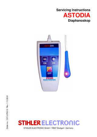
Servicing Instructions
ASTODIA
Order no.: 1211.6700.12 Rev. 1 11/2012
Diaphanoskop
STIHLER ELECTRONIC GmbH • 70597 Stuttgart • Germany
To be filled in by user: Serial number Stock number Location of device Date of commissioning
Manufacturer:
STIHLER ELECTRONIC GmbH Julius-Hoelder-Strasse 36 70597 Stuttgart GERMANY Tel. +49 (0) 711-720670 Fax +49 (0) 711-7206757 www.stihlerelectronic.de E-Mail: [email protected]
ASTODIA Servicing Instructions
1. General
CONTENTS 1. General ...4 Warranty terms ...4 Before repairs ...4 Repairs ...5 2. Product description...5 Introduction ...5 Technical Description...6 Components of the ASTODIA ...7 Components of the control panel ...7 3. Technical data...8 4. Troubleshooting ...8 5. Recurrent Tests ...9 Visual inspection ...9 Check the function of the yellow and the red LED ...9 Check the functioning of the reduction of the maximum light intensity and the automatic switching off. ...10 Electrical Test ...10 6. Exchange of the battery ...11 7. Spare parts list...13 Appendix 1 Examination report ASTODIA ...14
-3-
1. General
ASTODIA Servicing Instructions
1. General Technical service and spare part orders Germany STIHLER ELECTRONIC GmbH Julius-Hoelder-Strasse 36 70597 Stuttgart
Tel: +49-(0)711-72067-0 Fax: +49-(0)711-72067-57 e-mail: [email protected]
Warranty terms The warranty period is 12 months. During the warranty period, the manufacturer will repair or exchange free of charge any defects attributable to faulty materials or workmanship. Other damage is not subject to this warranty. There is no claim under warranty in the event of misuse or incorrect handling, use of force or in the event of damage attributable to normal wear and tear. This applies equally to interference by persons not so authorized by the manufacturer or in the event of modifications to the original state. In the event of damage during the warranty period, return the cleaned device to your nearest sales outlet or direct to STIHLER ELECTRONIC GmbH. The sender is to bear any transport or packing costs incurred.
Before repairs The ASTODIA may only be repaired by STIHLER ELECTRONIC GmbH or by service engineers expressly authorized by the manufacturer. STIHLER ELECTRONIC GmbH accepts no liability for the reliability, function and safety of the device if: • modifications or repairs are performed by unauthorized staff. • non-original spare parts are used. • the device is not used in accordance with the operating instructions. • the device is operated in an environment which does not conform to the applicable technical rules.
-4-
ASTODIA Servicing Instructions
2. Product description
Repairs Proper records are to be kept of all repair activities, tests performed and the results. Any change to its original state means that the device loses ses its certification, which is why only original ASTOPAD System spare parts should be used. Due to the safety risk, electronics boards may only be repaired by the manufacturer. They must be replaced in the event of faults. Risk of electric shock! Live parts are exposed on the dismantled device during the various assembly tasks and tests.
Disposing of the device Meaning of the symbol on the product, the packaging or the operating instructions: Electrical devices include valuable material and shall not be disposed of in the regular domestic waste! Please follow the local regulations for the disposal or used products or send the cleaned and sterilized device accompanied by a corresponding explanation to STIHLER ELECTRONIC GmbH or to your next dealer. dealer This is the way to ensure the cost-effective effective and professional disposal of your used appliances.
2. Product description Introduction The method of transillumination or Diaphanoscopy has been used in the field of paediatrics and especially of neonatology for decades. It is used to identify a pneumothorax or a hydrocele quickly and to visualize vessels in limbs during a puncture. Until now, cold light sources with fibre-optical light cables have been used for this purpose. Nowadays, however, the light emitting diodes (LED) are more often applied. Because of its design, the ASTODIA is particularly suitable for the patient-specific application on small premature babies.
-5-
2. Product description
ASTODIA Servicing Instructions
Technical Description ASTODIA consists of a control unit, a hand piece and a charger. Its light in the visible spectrum (yellow/red) is used for the transillumination of thin limbs (e.g. wrist joint) and for the quick identification of a pneumothorax or a hydrocele in the field of paediatrics/neonatology. The extremely bright light of the used high-performance diodes is adjustable in 9 steps or infinitely variable. The special yellow coloured light visualizes the vessel structures particularly well, as it is required for venipuncture. The red light ensures a continuous, extensive and deep transillumination, which is required for visualizing the pneumothorax or for diagnosing the hydroceles. The common interface on the control unit is designed for charging the integrated batteries as well as for the electrical connection of the hand piece cable. This avoids using and charging of the device at the same time. This way, the charger, when it is charging the device, cannot be seen as a medical device in the sense of the Medical Devices Directive provided the distance to the patient (min. 1. 5 m) is kept.
-6-
ASTODIA Servicing Instructions
2. Product description
Components of the ASTODIA 1
Control unit
2
Hand Piece
3
Charger
It includes the complete electronic circuitry and the power supply of the unit. The interface, which is used for the charger and the hand piece ensures that the patient is only treated without galvanic connection to the power mains. Two high-performance diodes of different wave lengths (yellow and red) provide for a wide field of application. The round and edge-free design allows the transillumination also on positions which are difficult to access. The intelligent charging management ensures that the integrated batteries work for a long time.
Control unit Hand Piece
Charger
Fig. 1
Components of the control panel 1
Shift key for LED-colours - press shortly OFF button - press and hold (ca. 1 s)
2
ON button Reduce the light intensity
3
ON button Increase the light intensity
-7-
ASTODIA Servicing Instructions
3. Technical data
3. Technical data ASTODIA Electr. connection while charging
100 - 240 VAC ±10% 50-60Hz Charger
Electr. connection during operation
4.8 V integrated, rechargeable battery Control unit and hand piece
Protection class
Charger II
IP (IEC 60529)
IPX0
Classification as per Appendix IX
I (rule 9)
Dimensions max. Length max. Width max. Depth
Control unit 141 mm 63 mm 33 mm
Hand piece Cable 1150 mm 19 mm 12 mm
Charger Cable 1000 mm 60 mm 50 mm
Weight
Control unit 0.2 kg
Hand piece 0.03 kg
Charger 0.4 kg
Permissible Environmental Conditions
Humidity
Temperature
Pressure
in operation in storage/ transport
10 % to 90 % 10 % to 90 % not condensing
+16 °C to +32 °C - 20 °C to +60 °C
700 hPa to 1060 hPa 500 hPa to 1060 hPa
Do not use the ASTODIA Diaphanoscope in an environment at risk of explosion.
4. Troubleshooting Symptom Device cannot be started
Batteries cannot be charged
-8-
Possible cause(s) Battery charge too low. Hand piece is not connected. Control unit or hand piece defect. Charger defect. Batteries defect.
Remedy 1. Charge battery 2. Connect the hand piece. 3. Send the control unit and the hand piece to the local dealer. 1. Replace charger 2. Replace rechargeable batteries.
ASTODIA Servicing Instructions
5. Recurrent Tests
5. Recurrent Tests A check needs to be performed after any repair work to ensure perfect function, performance and safety (it is also recommended that these tests be performed before repairs to assist troubleshooting). At least every 24 months - and/or in accordance with the applicable regional and national regulations – it is necessary to check the ASTODIA Diaphanoscope for safety reasons and to document it. The check consists of the following tests: • • • •
Visual inspection Check the function of the yellow and the red LED Check the functioning of the reduction of the maximum light intensity and the automatic switching off. Regionally and nationally required examinations of medical equipment (e.g. electrical safety of the ASTODIA charger)
All tests of the periodic safety inspection have to be passed! If one of the tests does not pass, the ASTODIA has to be sent to the local dealer or to STIHLER ELECTRONIC GmbH for repair.
Instructions for the test Visual inspection Check the following components for completeness and visible damages before each application. -
Charger Housing of the control unit Control panel Hand piece
Check the function of the yellow and the red LED -
Switch on the ASTODIA on the control unit. The red and yellow LEDs each has to flash three times. The red LED must light up at its lowest level. Actuate the shift-key for the LED-colours. The yellow LED must light up at its lowest level. Check, if it is possible to change the light intensity by actuating the keys / . Check, if the covering glasses of the LEDs are still clear and lighttransmitting.
-9-
5. Recurrent Tests
ASTODIA Servicing Instructions
Check the functioning of the reduction of the maximum light intensity and the automatic switching off. -
Switch on the ASTODIA on the control unit and set the maximum light intensity. Watch the LED and measure I.
II.
the time, until the ASTODIA automatically reduces the maximum light intensity by one level. This time must be 2 minutes +/- 10 s. the time, until the ASTODIA automatically switches off completely. This time must be 5 minutes +/- 30 s.
Electrical Test The charger has to be checked once a year according to the applicable national safety regulations.
- 10 -
ASTODIA Servicing Instructions
6. Exchange of the battery
6. Exchange of the battery
1. To open the ASTODIA control unit unscrew the 2. Lift the upper housing part from the lower for screws on the downside oft he housing. housing part.
3. Pull the connection plug from the power control 4. Now the battery can be removed from the board. lower housing part.
5. Insert new battery in the lower housing part. When putting the connection plug back make sure the red cable is positioned close to the housing part.
6. When assembling the upper and the lower housing make sure the flatband - connection cable is not squeezed between front plate and power supply board!
- 11 -
6. Exchange of the battery
ASTODIA Servicing Instructions
Tests according to chapter 5 „Recurrent Tests“
7. After reassembling screw the four screws again.
- 12 -
ASTODIA Servicing Instructions
7. Spare parts list
7. Spare parts list Bestell-Nr. DIA100
Artikel ASTODIA Completely packaged consisting of: 1 piece control unit 1 piece hand piece 1 piece charger 1 piece Operating instructions
DIA120
Control unit
DIA130
Hand piece
DIA140
Charger
1211.0001
Rechargeable Battery
0811.7200.11
Operating instructions
- 13 -
ASTODIA Servicing Instructions
Appendix 1 Examination report
ASTODIA
Appendix 1 Examination report ASTODIA Prüfprotokoll ASTODIA Examination report ASTODIA SN: _________________ Datum / Date:
Steuergerät / Control Unit
____________
SN: _________________ Prüfer / Carried out by: ____________
Handstück / Handpiece
SN: _________________ Ladegerät / battery charger
Sichtprüfung / visual check:
ok
n.ok
Einzelprüfung Handstück / handpiece check:
ok
n.ok
Prozessorprüfung / processor check
ok
n.ok
3 x wechselseitiges Blinken rote und gelbe LED 3 x alternate blinking red an yellow LED
Funktionsprüfung / function check: Stufenprüfung rote LED/step check red LED
Stufe / step 1 2 3 4 5 6 7 8
ok ok ok ok ok ok ok ok
Stufenlose Funktion steplessly variability
n.ok n.ok n.ok n.ok n.ok n.ok n.ok n.ok ok
n.ok
Stufenprüfung gelbe LED/step check yellow LED
Stufe / step 1 2 3 4 5 6 7 8
ok ok ok ok ok ok ok ok
Stufenlose Funktion steplessly variability
Sicherheits-Abschaltfunktion / security switch off function: 2-Minuten-Rückschaltung ok
n.ok n.ok n.ok n.ok n.ok n.ok n.ok n.ok ok
n.ok
2 minutes reduces the maximum 5-Minuten-Abschaltung 5 minutes switch off
ok
n.ok
Ladefunktion / charging function:
ok
n.ok
Ja / yes
Nein / no
Prüfung mit Ladegerät check battery charger
Prüfung bestanden / examination solved:
- 14 -
n.ok