Operators Manual
82 Pages
Preview
Page 1
®
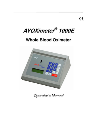
AVOXimeter 1000E Whole Blood Oximeter
Operator’s Manual
Manufacturing Company Location International Technidyne Corp 8 Olsen Avenue, Edison, New Jersey USA Phone: 1-732-548-5700 Fax: 1-732-248-1928 web site: www.itcmed.com
Copyright and Trademarks Copyright© 2007 International Technidyne Corporation (ITC). All rights reserved. This material may not be reproduced or copied, in whole or in part, without the written permission of ITC. ITC and AVOXimeter are registered trademarks of International Technidyne Corporation in the United States and other jurisdictions. U.S. Patents. 5,430,542 and 6,262,798. Euro/UK Patent 0663070. Other patents pending.
Technical Support Contact ITC Technical Support at (800) 631-5945 or (732) 548-5700, or by e-mail at [email protected].
ii
Table of Contents 1
INTRODUCTION ...1 Intended Use of the ITC AVOXimeter 1000E ... 1 Summary and Explanation of the Test ... 1 Hemodynamic Calculations ... 2 Saturation Step-Ups ... 3 Operating Precautions and Warnings ... 5 Limitations... 5
2
DESCRIPTION ...6 Front Panel ... 6 Keypad ... 7 Menus ... 8 Test Cuvettes ... 9 Connections ... 10 Automatic Standby and Shutdown ... 10 Instrument Lockouts... 10 Instrument Specifications ... 11 Reportable Range... 11 Accuracy ... 11 Precision ... 11 Interference... 11 Calibration... 12
3
GETTING STARTED ...13 Unpacking and Inspection... 13 Materials Provided ... 13 Materials Required But Not Provided ... 13 Optional Materials... 14 Charging the Batteries ... 14 Setting Up the Instrument ... 15 Setting Display Backlighting ... 15 Specifying Units for Total Hemoglobin (THb) ... 15 Changing the Date and Time... 16 Setting the Standby Delay ... 17 Specifying Mandatory Entry of User ID and/or Patient ID ... 18 Changing the QA User ID ... 21 Requiring Entry of a Patient ID ... 22 Specifying Oximetry Site Prompts... 23 Specifying Use of Oximetry Sites ... 24 Entering a Different Value for Hüfner’s Number ... 25
iii
4
OPERATION ... 27 Startup ...27 Entering a User ID (Optional) ...27 Entering a Patient ID (Optional)...27 Sample Collection and Preparation ...28 Sample Collection ...28 Sample Preparation...28 Running a Test ...29 Using the Printer...30 Printing the Current Test Results ...30 Specifying Automatic Printing of Results...30 Changing the Serial Port Baud Rate and Parity ...30 Data Management ...31 Printing all Stored Data ...31 Printing All Optical Quality Control Data...31 Reviewing and/or Printing the Last Sample ...32 Locating, Reviewing, and/or Printing any Sample ...32 Aborting Printing of Results...33 Purging all Test Records ...33 Quality Control...34 Performing Optical Quality Control...34 Running Liquid Controls ...35 Entering Liquid Control Lot Numbers ...36 Tagging a Liquid Control Test with a Lot Number ...37 Enabling QC Lockout ...38 Calibration ...39 Cuvette Pathlength...39 Re-Calibration ...39 Shutdown...40 Hemodynamic Calculations ...41 Entering the Patient Age, Height, Weight, and Sex...41 Oxygen Uptake Rate ...43 Body Surface Area ...44 Saturation Step-Ups ...45 Flow Calculations ...46 Systemic and Pulmonary Resistances ...50 Stroke Volume and Stroke Index...52 Printing Hemodynamic Values ...54 Troubleshooting...55
5
MAINTENANCE ... 59 Cleaning the Optical Detector...59 Replacing the Battery ...63
iv
6
QUALITY CONTROL LOGS ...65
7
WARRANTY ...68 Certification, Warranty and Service Warranty, and Service ... 68
8
SAFETY STANDARDS ...70 Guidance and Manufacturer’s Declaration – Electromagnetic Emissions ... 71 Guidance and Manufacturer’s Declaration – Electromagnetic Immunity ... 72
INDEX
...73
v
Important Labels and Symbols Before using the ITC AVOXimeter 1000E, it is essential that the contents of this Operator’s Manual, any labels on the instrument or its packaging, and instructions accompanying ITC AVOXimeter 1000E cuvettes are read and understood by the operator. These materials make reference to additional symbols that are explained below: Product Conforms to Directive 98/79, 27 October 1998 on In-Vitro Diagnostic Medical Devices Expiration Date of Cuvettes Serial Number of Instrument Lot Number of Cuvettes ITC Catalogue Number of Devices Do Not Reuse– Single Use Only Upper and Lower Temperature Limitations (For Storage or Use) For in vitro Diagnostic Use Attention - Read Accompanying Documentation or Instructions Consult Instructions for Use Input Port for DC Power Cord from AC/DC Power Module - Polarity, VDC and A Input Serial Output Port for Data Transfer – RS232C Temperature Probe Input (ITC AVOXimeter 4000 Only) Name and Address of Manufacturer Warning - Biohazard Medical Equipment per Annex 1A, Item 8 Directive 2002/96/EC For Electronic Equipment Waste – Contact ITC Technical Support @ 1-800-631-5945
vi
ITC AVOXimeter 1000E Operator’s Manual
1 Introduction Intended Use of the ITC AVOXimeter 1000E The ITC AVOXimeter 1000E is a battery-operated bedside whole blood oximeter that performs individual point-of-care measurements of oxyhemoglobin saturation (%Hb02) and total hemoglobin concentration [THb] on freshly-drawn or heparin or EDTA anticoagulated whole blood samples. Oxygen content [02] of the blood sample is automatically calculated from the %Hb02 and THb measurements. No sample preparation is required, and analysis is quickly accomplished by injecting the sample into a disposable cuvette and inserting the cuvette into the instrument. The ITC AVOXimeter 1000E then illuminates the sample with multiple wavelengths, records the optical density of the sample at each of the wavelengths, and computes the results. In less than 10 seconds, the oxyhemoglobin fraction, the total hemoglobin concentration, and the oxygen content of the sample are shown in appropriate units on the liquid-crystal display on the front panel. Data management capabilities are included with the instrument. These capabilities include storage of up to 500 patient or QC results, designation of quality control levels and lot numbers, tagging of test results with date, time, Patient ID and/or Operator ID, entry of oximetry site and subsite, and printing of results. The instrument also can calculate ten hemodynamic variables (such as body surface area, estimated oxygen consumption rate, and cardiac output using the Fick principle) from data that are entered by the operator. It can also calculate differences in oxygen saturation between adjacent anatomical sites from which blood samples were taken (saturation step-ups), to aid in diagnosing intracardiac and great vessel shunts.
Summary and Explanation of the Test The ITC AVOXimeter 1000E measures whole blood %Hb02 and [THb] using disposable singleuse cuvettes. The operator inserts a whole blood sample into a cuvette, the cuvette is inserted into the test chamber on the instrument, and the results are displayed. The results will remain on the display while the cuvette remains in the instrument. The result can be automatically printed along with the time and date the test was run, the Patient ID, Operator ID, and other information entered. The result is also saved in an internal database, which has the capability to store up to 500 results. Individual ITC AVOXimeter 1000E instruments can be customized so that optical quality control tests must be performed whenever a specified period of time has elapsed. In addition, up to three liquid control lot numbers for each level of liquid QC can be stored in the ITC AVOXimeter 1000E and can be tagged to the stored or printed liquid QC records. The instruments can also be configured so that only authorized operators can operate the system and that patient IDs are required for each test run.
1
ITC AVOXimeter 1000E Operator’s Manual
The ITC AVOXimeter 1000E measures oxygenated hemoglobin [HbO2], deoxyhemoglobin [HHb], methemoglobin [MetHb], and carboxyhemoglobin [COHb] directly, using novel optics and multiple wavelengths. This reduces interference from dyshemoglobins and other interfering substances such as fetal hemoglobin and bilirubin and minimizes the effects of hemolysis. The measured values are used to calculate total hemoglobin [THb] and percent oxyhemoglobin saturation [%Hb02] of the sample, using the fractional method described below: [THb]
=
[%HbO2]
=
[HbO2] + [HHb] + [MetHb] + [COHb] [HbO2] x 100 [HbO2] + [HHb] + [MetHb] + [COHb]
Oxygen content [O2] of the sample is then calculated: [O2]
1.39 x [THb] x [%HbO2]
=
100
where 1.39 is the ml of oxygen assumed to be carried by one gram of oxygenated hemoglobin (Hϋfner’s Number). Depending on your facility protocols, the Hϋfner’s Number stored in the ITC AVOXimeter 1000E can be set at any value in the range of 1.30 to 1.39 (see page 25). Note:
Below is a legend for oxygen saturation terminology used throughout this document: Abbreviation
Term
Units Displayed
THb
Total Hemoglobin
g/dl
HbO2
Oxyhemoglobin
g/dl
MetHb
Methemoglobin
g/dl
COHb
Carboxyhemoglobin
g/dl
HHb
Reduced Hemoglobin
g/dl
%HbO2
Percent Oxyhemoglobin Saturation (Fractional Oxygen Saturation)
n/a
[O2]
Oxygen Content
ml/dl
Hemodynamic Calculations Based on the results, hemodynamic calculations are performed as described below. Cardiac Output ml/min
2
=
Oxygen Uptake [O2] arterial - [O2] venous
ITC AVOXimeter 1000E Operator’s Manual
Note:
Oxygen uptake rate can either be measured from expired gases, or it can be estimated from the patient’s age, height, weight, and sex (see below).
Body Surface Area m2
=
0.007185 (Weight kg)0.425 (Height cm)0.725
Oxygen Uptakemales ml/min
=
157.3 BSA + 10– (10.5 * age + 4.8)
Oxygen Uptakefemales ml/min
=
157.3 x BSA – (10.5 * age + 4.8)
Cardiac Index L/min/ m2
Cardiac Output =
Stroke Volume ml/beat
=
Stroke Index ml/beat/m2
=
Pulmonary Blood Flow ml/min
=
Total Systemic Resistance mmHg/ml/min
=
Total Pulmonary Resistance mmHg/ml/min
=
Pulmonary to Systemic Flow Ratio
=
Pulmonary to Systemic Flow Ratio
=
BSA Cardiac Output Heart rate Stroke Volume BSA Oxygen Uptake [02] Pulmonary Arterial – [02] pulmonary venous Arterial Pressure – Right Atrial Pressure Cardiac Output Pulmonary Arterial Pressure – Left Atrial Pressure Cardiac Output Pulmonary Flow Systemic Flow %Hb02 Arterial – %Hb02 Venous %Hb02 Pulmonary Venous – %Hb02 Pulmonary Arterial
Saturation Step-Ups Saturation step-ups are the differences in oxyhemoglobin saturation [%Hb02] between adjacent anatomical sites. These values are used as an aid in diagnosing intracardiac and great vessel shunts. The ITC AVOXimeter 1000E calculates saturation step-ups between the following anatomical sites: ● ● ●
Right atrium and superior vena cava Right ventricle and right atrium Pulmonary artery and right ventricle
3
ITC AVOXimeter 1000E Operator’s Manual
● ● ●
Pulmonary vein and left atrium Left atrium and left ventricle Left ventricle and aorta
When calculating saturation step-ups, the ITC AVOXimeter 1000E searches the database for all results for each main oximetry site for that patient (sub-sites are ignored), averages the results for each site, and then calculates the saturation step-ups from the average result for each main site. This information can then be printed from the ITC AVOXimeter 1000E. Note:
4
Use of average readings rather than individual values improves the precision of saturation step-up calculations.
ITC AVOXimeter 1000E Operator’s Manual
Operating Precautions and Warnings ●
For in vitro Diagnostic use.
●
Do not allow blood, water, or other liquids to enter the instrument.
●
The ITC AVOXimeter 1000E instrument is designed for use only with ITC AVOXimeter 1000E cuvettes.
●
Do not re-use test cuvettes.
●
Always keep cuvettes in sealed bag with desiccant.
●
When filling cuvette, do not use excessive pressure on the syringe or cause the vent patch to bulge outward by overfilling the cuvette.
●
For proper calibration and calibration verification, use only the controls recommended in this manual. Controls from other sources may yield erroneous results.
●
The ITC AVOXimeter 1000E instrument is designed to be used for testing in a stationary position. DO NOT perform testing while carrying or holding the instrument.
●
In order to charge the ITC AVOXimeter 1000E instrument, the AC power cord should be plugged into an electrical service outlet and the AC/DC power module while the DC power cord from the AC/DC power module is plugged into the DC port in the back of the instrument.
●
DO NOT expose the ITC AVOXimeter 1000E instrument to extreme temperature (above 35°C, 95°F). Such exposure could affect the performance of any type of electronic instrumentation.
●
DO NOT drop the ITC AVOXimeter 1000E instrument, and do not use the results if the instrument is dropped during a test.
●
Only properly qualified personnel should attempt to open and perform work on the ITC AVOXimeter 1000E instrument as identified in this manual.
●
DO NOT remove the AC/DC power module from the ITC AVOXimeter 1000E instrument by pulling on the cord.
●
The use of accessory equipment (e.g., printers, etc.) not identified in this manual either in the patient vicinity, or that does not comply with either the equivalent safety requirements of this equipment or UL/IEC 60601-1 or IEC 60601-1-2, may lead to a reduced level of safety with the resulting system.
Any items exposed to human blood, plasma or serum must be handled cautiously as a biohazardous material in accordance with laboratory safety practices and federal and local regulations. Federal, state and local laws and regulations require that hazardous waste be disposed of in a specific manner. Waste material from the ITC AVOXimeter 1000E which may be classified as biohazardous include used cuvettes. It is important that steps be taken to dispose of these materials in accordance with the prevailing regulations in your location.
Limitations Do not disturb the instrument while a test is in progress. As with all diagnostic tests, ITC AVOXimeter 1000E test results should be scrutinized in light of a specific patient’s condition and therapy. Any results exhibiting inconsistency with the patient’s clinical status should be repeated or supplemented with additional test data.
5
ITC AVOXimeter 1000E Operator’s Manual
2 Description The ITC AVOXimeter 1000E is a Point of Care device for use at the bedside. It contains a test chamber which performs all operations to measure the oxyhemoglobin saturation (%Hb02), total hemoglobin (THb), and oxygen content (O2) of a whole blood sample after the operator inserts a test cuvette containing the sample into the test chamber. Each ITC AVOXimeter 1000E is calibrated at the factory. The ITC AVOXimeter 1000E can be operated either from its internal batteries or from the AC adapter. The batteries are charged when the AC Adapter is connected.
Finger Grip
Test Cuvette
Figure 1. ITC AVOXimeter 1000E Oximeter
Front Panel The front panel (Figure 2) contains the test chamber, a keypad with the key, action and menu keys, number keys, and a display panel. Operator instructions are shown on the display panel, and the operator enters commands and information using the keypad. When the test is completed, the results are shown on the display panel and stored in system memory. The display panel is illuminated to enhance visibility in low light conditions. The illumination can be adjusted (or turned off) to conserve power during battery operation.
6
ITC AVOXimeter 1000E Operator’s Manual
Test Chamber
Number Keys (Blue)
Action Keys (White)
Enter/On Key (Red)
Display Panel
Menu Keys (White)
Figure 2. Front Panel
Keypad The routine analysis of blood samples does not require the use of menus or the numeric keypad. However, these enable the user to take advantage of many useful features. The purpose of each key is summarized below: Key
Purpose Switch the instrument on. Select a command. Display a menu of commands for calibration, printing, stored data, and shutdown. Display a menu of commands for entering hemodynamic variables, entering device settings, entering the time and date, viewing battery status, and managing data. Print the results that are displayed. and
Respond to questions that are displayed. Backspace over a numerical entry (such as a QC lot number) so that it can be corrected. Return to the previous menu.
to
Enter characters for Operator IDs or Patient IDs. Enter a character for selection of a command.
7
ITC AVOXimeter 1000E Operator’s Manual
Menus The principal menus, their commands, and the procedure to access each menu are summarized below: Note:
Press the
Menu
Main Menu
Commands
Access key when a test is not Press the running or another menu is not active.
Calibration Submenu
Press followed by main menu is displayed.
while the
Printer Mode Submenu
Press followed by main menu is displayed.
while the
Stored Data Submenu
Press followed by main menu is displayed.
while the
Computer Menu
Hemodynamics Submenu (Page 1)
8
button at any time to return to the previous menu.
Press the key when a test is not running or another menu is not active.
followed by while the Press computer menu is displayed to display Page 1.
Hemodynamics Submenu (Page 2)
Press + or - while the hemodynamics submenu is displayed to toggle between Page 1 and Page 2.
Device Settings Submenu
Press followed by while the computer menu is displayed.
Time, Date, and Battery Submenu
Press followed by while the computer menu is displayed.
Data Management Submenu
followed by while the Press computer menu is displayed.
ITC AVOXimeter 1000E Operator’s Manual
Test Cuvettes Tests are performed with single-use disposable test cuvettes (Figure 3). Each test cuvette contains a finger grip, filling port, optical window, and a vent patch.
Filling Port Finger Grip Optical Window
Light Path Vent Patch
Figure 3. Test Cuvette A whole blood sample is inserted into a test cuvette by connecting a luer lock syringe, slip syringe or capillary tube containing the whole blood sample to the filling port and then gently pressing the syringe plunger to dispense approximately 50 µL of whole blood into the test cuvette. Air escapes from the vent patch at the end of the test cuvette while the whole blood sample is being inserted. The test cuvette (with the syringe still attached) is then inserted into the test chamber of the instrument (see page 28 for details). Note:
Be sure to handle the cuvette either by the edges or by the finger grip. Refer to the package insert accompanying the test cuvettes for storage and handling instructions.
●
Remove any blood or debris from the exterior of the test cuvette before inserting it into the test chamber.
●
After filling the cuvette with blood, inspect the vent patches to ensure they are not bulging out. If a vent patch protrudes, discard the cuvette. Do not insert a cuvette with a protruding vent patch into the test chamber.
BIOHAZARD WARNING: Any items exposed to human blood, plasma or serum must be handled cautiously as a biohazardous material in accordance with laboratory safety practices and federal and local regulations. Federal, state and local laws and regulations require that hazardous waste be disposed of in a specific manner. Waste material from the ITC AVOXimeter 1000E which may be classified as biohazardous include used cuvettes. It is important that steps be taken to dispose of these materials in accordance with the prevailing regulations in your location.
9
ITC AVOXimeter 1000E Operator’s Manual
Connections Connections to the AC Adapter and an optional printer (or a computer) are made at the rear of the instrument (Figure 4). Use only the AC Adapter provided with the instrument.
Serial No. Label
AC Adapter
Printer or Computer
Figure 4. Power and Printer Connections
Automatic Standby and Shutdown The ITC AVOXimeter 1000E enters a low-power standby mode after the instrument has been idle for a specified period of time (the standby delay). The instrument is factory preset for a standby delay time of 60 minutes, but a time of 10 to 180 minutes can be specified (see page 17). To resume normal operation when the instrument is in standby, press and hold down any key for one second. Note:
The ITC AVOXimeter 1000E also enters standby if the battery charge becomes critically low.
The ITC AVOXimeter 1000E shuts down after it has been in standby for 4 hours.
Instrument Lockouts The instrument can be configured to allow use only by authorized operators and/or to allow use only if Optical Quality Control (OQC) has been performed.
10
ITC AVOXimeter 1000E Operator’s Manual
Instrument Specifications Size Weight Operating Temperature Battery Type Operating Time On Battery Anticipated Battery Life Power Supply/Chargers Serial Data Port Sample Type Sample Volume Analysis Time Analysis Wavelengths
20.3 cm (8.0 in) x 25.4 cm (10.0 in) x 9.5 cm (3.8 in) 1.8 kg (4 lbs) Room temperature (15°C to 30°C, 59°F to 86°F) Nickel Cadmium (NiCad) Approximately 8 hours (constant run at medium brightness). Tests may also be run while the ITC AVOXimeter 1000E is plugged into the AC/DC power module. Approximately 500 charge / discharge cycles Input: 100 / 240 VAC, 50 / 60 Hz Output: 12 VDC, 830 mA RS232C Whole blood 50 µL 7 to 10 seconds per sample 5
Reportable Range %HbO2 THb [O2 Content]
0 to 100% 4 to 25 g/dL 0 to 35 mL O2/dL
Accuracy %HbO2
±1 %HbO2
THb (>10 g/dL)
±0.45 g/dL
THb (<10 g/dL)
±0.35 g/dL
Precision %HbO2 THb
0.5 %HbO2 0.3 g/dL
Interference Bilirubin
None
Hemolysis
None
Carboxyhemoglobin
None
Methemoglobin Fetal Hemoglobin
< 1% %HbO2, < 0.2 g/dL THb (THb = 16 g/dL, MetHb < 10%, 7.1 < pH < 7.8) < 1% %HbO2, < 0.45 g/dL THb (THb = 16 g/dL, HbF < 100%)
11
ITC AVOXimeter 1000E Operator’s Manual
Calibration The ITC AVOXimeter 1000E is factory-calibrated and employs highly stable state-of-the-art light sources. Factory tests indicate that, when used in accordance with this Operator’s Manual and other instructions, the ITC AVOXimeter 1000E is capable of maintaining its calibration for at least two years. Should recalibration be required contact an ITC technical support representative for assistance (see page 39). Proper calibration also requires entry of the correct cuvette pathlength by the user (see page 39) and use of a customary value for Hüfner’s number (see page 25). CAUTION: If quality control results are not acceptable, erroneous results are encountered, or error messages are displayed, the most likely cause is contamination of the optical detector by blood or debris, which cannot be resolved by re-calibration. Consult the Troubleshooting section for additional information.
12
ITC AVOXimeter 1000E Operator’s Manual
3 Getting Started Unpacking and Inspection Note:
Inspect each component for damage when unpacking. If damage is observed, contact your shipping representative immediately. 1.
Remove any protective packaging that may be present around the instrument.
2.
Examine the packaging material to be sure that the AC adapter, connecting cables, or other components have been removed. The materials that are provided are listed below. Note:
Do not discard the packaging material.
Materials Provided
Note:
Item
Quantity
ITC AVOXimeter 1000E Instrument
1
AC adapter
1
Operator’s Manual
1
Optical Quality Control Filters
2
An AC power cord is supplied only for the 110VAC version of the US/Canada/Japan instrument. For all others, the customer must obtain a 3 conductor AC power cord that is compatible with an IEC 320 connection at the power supply AC inlet and any other local requirements.
Materials Required But Not Provided Item
Quantity
ITC AVOXimeter 1000E Cuvettes
As Needed
Liquid Controls (Manufactured by IL or RNA) See page 34 for additional information.
As Needed
13
ITC AVOXimeter 1000E Operator’s Manual
Optional Materials Item
Quantity
Dymo Printer • 110 V (Part No. SE300-110) • 220 V (Part No. SE300-220) • UK V (Part No. SE300-UK)
1
Printer Paper (Part No. 30270)
As Needed
Charging the Batteries Charge the batteries before the system is used for the first time. 1.
Plug the AC adapter into an electrical service outlet.
2.
Connect the AC adapter cord to the power connector on the rear of the instrument.
3.
Allow the battery to charge for at least eight hours. Note:
4.
The AC Adapter can remain connected all the time.
To ensure adequate charge, leave the instrument connected to the AC adapter for a minimum of eight hours. This eliminates the risk of the instrument powering down during a test.
Fully charged batteries will allow the ITC AVOXimeter 1000E to analyze blood samples continuously for up to 8 hours when the display is set at medium brightness. Battery power can be conserved by: ● ●
Note:
Reducing (or turning off) display backlighting (see page 15). Reducing the standby delay (see page 17). The batteries can suffer from a “memory effect” if they are charged before being completely discharged. For optimal battery performance, discharge completely when possible before charging them. The message “Battery Critical – Connect Charger” will be displayed when the battery is completely discharged.
The message “Battery Critical – Connect Charger” is displayed and the instrument reverts to the standby mode if the battery power is insufficient to complete the test. The AC Adapter must be used for additional tests until the battery is recharged. Checking the Battery:
14
1.
Display the “Time, Date, and Battery” menu (a submenu of
2.
Press
followed by
to display the battery status:
, see page 8).