BOWA-electronic
BOWA ARC 350 Service Manual Ver 2.1.0 Jan 2019
Service Manual
115 Pages
Preview
Page 1
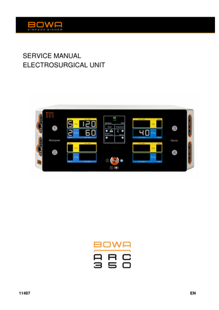
SERVICE MANUAL ELECTROSURGICAL UNIT
11497
EN
ARC 350
BOWA-SM-11497-ARC351-V2.1.0-S2-EN-20190101
ARC 350 Service Manual
3
4
ARC 350 Service Manual
BOWA-SM-11497-ARC351-V2.1.0-S2-EN-20190101
BOWA-SM-11497-ARC351-V2.1.0-S2-EN-20190101
ARC 350 Service Manual
5
Key
6
11
Key
8
Front of ARC 350 1
2 3
1
3 2 4
5
7
12
10
13
12
9
4
Connection socket 4 for bipolar instruments with US 2-pin type connectors or 1 x ERBE bipolar connectors
5
Socket for the neutral electrode (NE)
6
10 11
Activation indicator, socket 1 “Monopolar Cut” (yellow) / “Monopolar Coag” (blue) Activation indicator, socket 2 “Monopolar Cut” (yellow) / “Monopolar Coag” (blue) Activation indicator, socket 3 “Bipolar Cut” (yellow) / “Bipolar Coag” (blue) Activation indicator, socket 4 “Bipolar Cut” (yellow) / “Bipolar Coag” (blue) On/Off switch with light ring (orange) TFT display with touch function
12
Navigation button “up/down”
13
Confirmation button
7 8
14
16
17
18
13
19
Connection socket 1 for monopolar instruments that can be switched by hand or foot. Possible connection configurations are 3-pin, 4mm, Bovie or optional ERBE monopolar connections. Connection socket 2 for monopolar instruments that can be switched by hand or foot. Possible connection configurations are 3-pin, 4mm, Bovie or optional ERBE monopolar connections. Connection socket 3 for bipolar instruments with US 2-pin type connectors or 1x ERBE-bipolar connector
9
Back of ARC 350
27
20
21
22
23
24
25
26
15
6
14
Right speaker
15
Left speaker
16
Connection socket 1 for footswitch
17 18
Connection socket 2 for footswitch Connection for potential equalization
19
Mains connection for IEC connector
20 21
Fibre optic cable signal input socket Fibre optic cable signal output socket
22 23 24
LAN network connection (not used) USB port Audio Line-IN socket (not used)
25 26 27
CAN / UART communication interface Mains switch Rating plate
ARC 350 Service Manual
BOWA-SM-11497-ARC351-V2.1.0-S2-EN-20190101
BOWA-SM-11497-ARC351-V2.1.0-S2-EN-20190101
ARC 350 Service Manual
7
Table of Contents
Table of Contents 1.
2.
3.
Using this Service Manual ...11 1.1.
Index of revisions ...11
1.2.
Validity...11
1.3.
Other applicable documents ...11
1.4.
Symbols and markings ...12 1.4.1.
Structure of warnings ...12
1.4.2.
Risk levels in warnings...12
1.4.3.
Information ...12
1.4.4.
Other symbols and markings ...13
Safety information for service technicians ...14 2.1.
Safety information ...14
2.2.
Warnings and safety instructions ...14 2.2.1.
General instructions ...14
2.2.2.
Special instructions ...15
2.2.3.
Working with the unit switched on ...15
2.2.4.
Working with the unit switched off ...16
Design and operating principle ...17 3.1.
3.2.
3.3.
Power board ...18 3.1.1.
Power rectifier ...20
3.1.2.
Power supply unit (PSU) ...21
3.1.4.
Generator ...22
3.1.5.
Control electronics ...24
Control board...25 3.2.1.
EASY sensor ...27
3.2.2.
Fingerswitch electronics ...27
3.2.3.
Arc sensor ...27
3.2.4.
Current and voltage sensors ...28
3.2.5.
Power board interface ...28
3.2.6.
µ-processor...29
3.2.7.
Low voltage supply ...30
3.2.8.
Footswitch interface ...30
Complete front panel unit...31 3.3.1.
8
DCU-Board (Display Control Unit)...33
ARC 350 Service Manual
BOWA-SM-11497-ARC351-V2.1.0-S2-EN-20190101
Table of Contents 3.3.2.
4.
3.4.
Low voltage power supply unit ...36
3.5.
Interface board ...37
3.6.
Socket switch board ...38
3.7.
Footswitch board ...40
Software-Update ARC 350 ...41 4.1.
5.
Instructions for the Software Update ...41
Maintenance ...46 5.1.
Technical safety inspection (TSI) ...46 5.1.1.
6.
Functional test of boards ...47 6.1.1.
6.2.
6.3.
6.4.
Dealing with a board fault...47
Information messages displayed on the electrosurgical unit ...47 6.2.1.
Procedure to be followed when information messages appear ...47
6.2.2.
Overview of information messages and the corresponding procedure to correct them ...48
Reading out the fault memory ...51 6.3.1.
Procedure to read out the fault memory ...51
Troubleshooting ...54 6.4.1.
Dealing with a board fault...54
6.4.2.
Start-up faults ...54
6.4.3.
Display faults ...56
6.4.4.
Voltage generation faults ...57
6.4.5.
Interference to other equipment ...57
Repairs...58 7.1.
Repair on site ...58 7.1.1.
7.2.
Ordering of spares ...58
Repair in the factory ...59 7.2.1.
8.
Carrying out the TSI ...46
Problem solving ...47 6.1.
7.
RFID boards (Radio-Frequency Identification) ...35
Warranty / Defects report ...60
Removal and installation of parts ...60 8.1.
Mains fuse ...61
8.2.
Opening / closing the electrosurgical unit ...62
8.3.
Power board ...63
8.4.
Low voltage power supply ...65
BOWA-SM-11497-ARC351-V2.1.0-S2-EN-20190101
ARC 350 Service Manual
9
Table of Contents
8.5.
Control board...66
8.6.
Socket switch board ...68
8.7.
Interface board ...70
8.8.
Footswitch board ...72
8.9.
Potential equalization connection ...73
8.10.
Connector socket / Mains filter...74
9.
Parts list ...75
10.
Technical specifications ...80 10.1.
11.
12.
10
Technical specifications for ARC 350 ...80
Test instructions for TSI ...84 11.1.
Visual inspection ...84
11.2.
Electrical safety test...85
11.3.
Functional test ...90
11.4.
Activation check ...95
11.5.
EASY neutral electrode monitoring ...101
11.6.
Measuring the HF output power Cutting / Coagulation ...103
11.7.
Test devices used ...106
11.8.
Final activities ...106
Appendix ...107
ARC 350 Service Manual
BOWA-SM-11497-ARC351-V2.1.0-S2-EN-20190101
1 Using this Service Manual
Using this Service Manual
1.
This Service Manual is an integral part of the product. BOWA electronic GmbH & Co KG will neither accept any liability nor provide any warranty in the event of direct or consequential damage arising as a result of non-compliance with the Service Manual. Carefully read through the Service Manual before using the unit. Keep the Service Manual in a safe place throughout the lifetime of the product.
Make sure the Service Manual is also available to service technicians.
Pass on the Service Manual to all subsequent owners/users of the product. Update the Service Manual by adding supplementary information provided by the manufacturer.
1.1.
Index of revisions ARC 350 unit version
Revision status
Valid from Version 2.1.0.
2019/01
The revision index is as follows: ARC 350 unit version
V 2.1.0. ARC 350 generation Software version of control/regulation/monitoring Software version of user interface (display)
1.2.
Validity
This Service Manual applies only to the product indicated on the title page.
1.3.
Other applicable documents Observe the other applicable documents in the appendix or in the other information.
BOWA-SM-11497-ARC351-V2.1.0-S2-EN-20190101
ARC 350 Service Manual
11
1 Using this Service Manual
Other applicable documents are: •
Appendix (optional)
•
User Manual
1.4.
Symbols and markings
1.4.1.
Structure of warnings SIGNAL WORD Type, source and consequences of danger (physical injury)! Measure for avoiding the danger.
NOTE Type, source and consequences of danger! Measure for avoiding the danger.
1.4.2.
Risk levels in warnings
Symbol Risk level
1.4.3.
Probability of occurrence
Consequences of non-compliance
DANGER
Immediate danger
Death, serious physical injury
WARNING
Possible risk
Death, serious physical injury
CAUTION
Possible risk
Minor physical injury
NOTE
Possible risk
Damage to property
Information
Additional information provided to facilitate working with the electrosurgical unit.
12
ARC 350 Service Manual
BOWA-SM-11497-ARC351-V2.1.0-S2-EN-20190101
1 Using this Service Manual
1.4.4.
Other symbols and markings Symbol / Marking
Meaning
Prerequisite for an action
Action with one step
1.
Action comprising several steps that must be carried out in a certain order
Result of preceding action
•
List (first level) •
List (second level)
Highlighting
Highlighting
... (see Section xxx, p. xxx)
Cross reference
... Socket 3
Numbers in bold type (here: 3) refer to the photos of the unit and the corresponding key at page 5-6
BOWA-SM-11497-ARC351-V2.1.0-S2-EN-20190101
ARC 350 Service Manual
13
2 Safety information for service technicians
Safety information for service technicians
2.
BOWA-electronic places great emphasis on safety when working with electrosurgical equipment. This section contains information on: •
Safety instructions
•
Warnings
The safety instructions in the User Manual contain information relevant to correct handling of the electrosurgical unit.
2.1.
Safety information
Electrosurgical equipment is subject to rigorous inspections by specially trained personnel. Only experienced and trained personnel may work with the electrosurgical unit. BOWA assumes that the electrosurgical unit will be maintained by qualified or authorised personnel. Service technicians must be trained and familiar with the basic principles, rules of maintenance and risks posed by the electrosurgical unit in order to ensure that patients, personnel and equipment are never put in danger.
2.2.
Warnings and safety instructions
2.2.1.
Position the electrosurgical unit safely; do not place it on top of electrical equipment. Do not place any objects (e.g. tools) on the electrosurgical unit.
Take suitable safety precautions before working on the electrosurgical unit, use isolating transformers, insulated tools and materials.
Connect the accessories only to the sockets provided. Set the activation signal volume so it is loud enough to be heard.
14
General instructions
ARC 350 Service Manual
BOWA-SM-11497-ARC351-V2.1.0-S2-EN-20190101
2 Safety information for service technicians
2.2.2.
Special instructions If necessary, the electrosurgical unit can be connected to the potential equalization system by means of an earthing cable.
2.2.3.
Replace sub-assemblies only with sub-assemblies of the same type and quality. Use antistatic containers to transport components that could be damaged by static electricity.
Working with the unit switched on DANGER Since the unit's components are not insulated against contact with foreign objects, there is high risk of electric shock with potentially fatal consequences! Work must only be carried out by qualified or authorised personnel.
Do not use mains extension cables, adapters or multi-way sockets. Use a 1000 VA isolating transformer if you are working on the unit when it is open. Ensure that the electrosurgical unit and all of its accessory parts are operated in dry conditions. Do not touch any unprotected cables or PCBs. Do not use any earthing straps when working on a live electrosurgical unit.
Overheated or unsuitable components and inflammable materials pose the risk of fire or explosion. Ensure that the electrosurgical unit has sufficient cooling.
Do not use any inflammable materials, such as anaesthetics, gases or fluids, around the electrosurgical unit. If accessories are overheated, remove them from the electrosurgical unit and keep them away from the unit and personnel.
BOWA-SM-11497-ARC351-V2.1.0-S2-EN-20190101
ARC 350 Service Manual
15
2 Safety information for service technicians
2.2.4.
Working with the unit switched off The components are not insulated against contact with foreign objects. There is a risk of electric shock from electrically charged components even after the unit is switched off.
CAUTION Risk of injury due to electric shock Voltages up to 380 V DC may be present.
Set a suitable voltage range on the measuring device.
Switch off the electrosurgical unit and pull out the plug at least 5 minutes before commencing any service work. Check for zero voltage by measuring the DC voltage between measuring points JP8 and JP3 on the power board (see Figure 2-1)
JP8
JP3
Figure 2-1: Zero voltage measuring points
Use an electrostatic discharge wrist strap and ESD mats, in order to prevent damage to the electronic components.
The electrosurgical unit can be damaged by incorrect use of tools and associated materials.
Do not clean the electrosurgical unit with cleaning agents which could cause damage or scratching.
Follow the cleaning instructions in the User Manual. When carrying out maintenance work, also observe the warnings and safety instructions in the User Manual.
16
ARC 350 Service Manual
BOWA-SM-11497-ARC351-V2.1.0-S2-EN-20190101
3 Design and operating principle
Design and operating principle
3.
The electrosurgical unit consists of several sub-assemblies connected together as blocks or modules: •
Power board
•
Control board
•
Interface board
•
Front unit, complete
•
Socket switch board
•
Low voltage power supply unit
•
Foot switch board
The following block diagram gives an overview of the components and their functions.
BOWA-SM-11497-ARC351-V2.1.0-S2-EN-20190101
ARC 350 Service Manual
17
3 Design and operating principle
3.1.
Power board The power board contains all the circuits required to generate the HF power from mains-frequency current. The power board is composed of various individual functions: power board is composed of various individual functions: 1
Power rectifier
2
Power supply unit
3
Power failure detection
4
Generator
5
Control electronics
2
1
3
5
4
Figure 3-1: Power board, viewed from component side
18
ARC 350 Service Manual
BOWA-SM-11497-ARC351-V2.1.0-S2-EN-20190101
3 Design and operating principle
The output voltages at the JP27 supply connector can be tested on the component side via test points TP28 – TP31. In addition, LEDs (D21 – D24) indicate the operational readiness of the voltages.
Figure 3-2: Test points/LEDs Power supply
Test point / LED
Output voltage
TP28 / D21
+15 V
TP29 / D22
+5 V
TP30 / D23
-15 V
TP31 / D24
+3.3 V
JP20
GROUND
There are two connectors on the solder side of the power board. The power board is connected to the control board via these plug connectors. 1
Control line (JP26)
2
Power supply (JP27)
1
2
Figure 3-3: Power board, viewed from solder side
BOWA-SM-11497-ARC351-V2.1.0-S2-EN-20190101
ARC 350 Service Manual
19
3 Design and operating principle
3.1.1.
Power rectifier
The power rectifier is connected via the power switch to the power input socket with integral mains filter. The power rectifier converts the mains voltage (AC) into two DC voltages (±160 V) for the switch-mode power supply. The supply voltage can be set between 115 V and 230 V via a voltage selector switch (see table below).
1
Voltage selector switch for the mains voltage configuration (115/230V)
2
Mains voltage connection
1
2
Figure 3-4: Power rectifier
Supply voltage
Voltage selector switch
Mains fuse to be used
115 V
Position 115V
T 10 AH
230 V
Position 230V
T 5 AH
NOTE Incorrect mains fuse rating may damage the unit!
20
When adjusting or changing over the voltage range, make sure that the correct rating for the mains fuse in the mains filter is used.
ARC 350 Service Manual
BOWA-SM-11497-ARC351-V2.1.0-S2-EN-20190101
3 Design and operating principle
3.1.2.
Power supply unit (PSU) The power supply unit is a full-resonance switch-mode power supply, with output voltage regulated by the MCU (Master Control Unit). It supplies output voltages between 0 V DC and 380 V DC.
JP1
JP2
Figure 3-5: Power supply unit
The output voltage of the power supply unit can be measured at test points. JP1 and JP2 using a multimeter. The output voltage varies depending on which mode, effect and output power is set.
CAUTION Risk of injury due to electric shock The electrosurgical unit must be switched off before connecting the measuring line.
Set a suitable voltage range on the measuring device.
BOWA-SM-11497-ARC351-V2.1.0-S2-EN-20190101
ARC 350 Service Manual
21