Technical Manual
42 Pages
Preview
Page 1
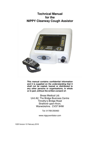
Technical Manual for the NIPPY Clearway Cough Assistor
This manual contains confidential information and it is supplied on the understanding that it shall not be copied, loaned or distributed to any other persons or organisations, in whole or in part, without the written consent of:
Breas Medical Ltd. Unit A2, The Bridge Business Centre Timothy’s Bridge Road Stratford–upon-Avon, Warwickshire. CV37 9HW Tel: 01789 293460 www.nippyventilator.com
1029 Version 10 February 2018
Contents Introduction
1
Description
2-3
Service Menus Time and Date
4
Service Period / Calibration
5
Diagnostic Screen
6
Alarm Log
7
Install Defaults
8
Fault Messages
9 – 10
Event Log
11
Opening the Case Fig 1. Opening the Case
12
Fig 2. Inside the base
13
Fig 3. Location of Components – Lid
14
Removal of Major Components
15 – 16
Suggest acceptance Test
17
Preventative Maintenance Guide
18
Servicing
19 Replacement of Alarm Battery
20
Calibration
21
The Valve, Description and disassembly
22
Fig 5. The Valve
23
Theory of Operation
24
Block Diagram
25
Block diagram of Control Board
26
Block diagram of Command Board
27
Circuit Diagrams
28- 38
Specification
39
Spare Parts List
40
Introduction The purpose of this manual is to enable suitably qualified competent technical personnel to perform first line maintenance on the NIPPY Clearway cough assistor. Component level fault finding will not be considered. Due to the complexity of the circuit boards used in the NIPPY Clearway, it is not considered practical or cost effective to try to trace faults to component level. Second-hand or “service exchange” boards are not available. This manual will deal with routine maintenance, calibration and replacement of major components.
This manual covers NIPPY Clearway machines running software version 1.11 or later. The software version is displayed on the boot up screen.
IMPORTANT Read this manual before attempting service or repair of the NIPPY Clearway. Please contact Breas Medical Ltd if training is required or you have any questions. NIPPY Clearway must be subjected to regular inspection according to Breas Medical Ltd service instructions. Repairs shall be carried out in accordance with this technical manual and any special service instructions or bulletins provided by Breas Medical Ltd. Before opening the case, disconnect the NIPPY Clearway from the mains supply. Do not work on the NIPPY Clearway with the case open and the power supply connected. Make sure that all precautions to prevent Electrostatic Discharge (ESD) have been taken. Do not use explosive gases and/or fluids near the NIPPY Clearway.
1
Description The NIPPY Clearway is a pressure controlled, mechanical insufflator / exsufflator cough assist machine. It assists in the mobilisation and clearance of bronchial secretions by inflating the lungs with a positive airway pressure then providing a rapid change to negative pressure to assist the patient’s cough. In auto modes a graphical representation of the treatment and an audible synchronisation signal is provided to help synchronise the cough effort with the shift to negative pressure. Ambient air is compressed by a turbine and delivered to the patient through a close fitting facemask, mouthpiece or a tracheostomy. Very accurate and consistent pressure control is achieved using the NIPPY Clearway’s unique bi-directional servo control valve and remote pressure sensing. The pressure displayed on-screen is the actual mask pressure. The output pressure and timing can be adjusted by controls on the fascia panel. The Pressure, and all settings are displayed on a colour LCD(Liquid Crystal Display) screen. The settings can be achieved using the buttons around the outside of the display. More advanced features and adjustments can be accessed via the menu. It is designed for non-continuous use. The NIPPY Clearway may be used for up to 30 minutes in any 1 hour period. For greater convenience the NIPPY Clearway may be powered by an external battery. There are 5 modes of operation:Manual
Positive and negative pressures are applied using the manual switch on the front of the machine or with a remote handheld switch plugged into the RS232 input.
Basic Auto
In basic auto mode the NIPPY Clearway cycles between insufflation and exsufflation followed by a pause, for a maximum of 20 cycles.
Timed Programmable Auto The NIPPY Clearway can be pre programmed to deliver a timed sequence, which could include one or more insufflations before exsufflation. This sequence can be repeated up to 10 times if desired.
2
Triggered Programmable Auto This is the same as the timed auto mode with patient trigger on insufflations. NIV
NIV mode is provided to give the patient up to 15 minutes of respiratory support to aid the recovery from the exertion of the cough assist treatment.
Alarms Low External Battery When running on an external battery, the alarm will operate when the battery is almost depleted. Machines fitted with an internal battery will automatically switch to internal battery power without alarming. High Pressure A pre-set high-pressure alarm is provided. If the pressure rises above 120% of the working pressure, a visual alarm will operate after a 2 second delay. Patient Pressure Tube Disconnected If the pressure pick up tube is not connected the NIPPY Clearway will use the internally measured pressure for control. A visual alarm will operate after a 2 second delay. This does not compensate for the length of the circuit. Reconnect the pressure tube for most effective treatment. Fault The alarm may also be operated by an internal fault. In this case the fault will be displayed on screen. These alarms may be cancelled by pressing the Set button. Low Internal Alarm/Memory Battery If the machine has been stored for more than a few months, the internal memory back up battery will self discharge. An intermittent alarm (short beep) with no onscreen message indicates a depleted memory back up battery. The alarm will stop after the battery has started to recharge. This may take a few minutes. The user cannot replace this battery. Refer to qualified technical personnel if the alarm operates when the NIPPY Clearway is in daily use.
Inspiratory Trigger The NIPPY Clearway employs a differential pressure triggering mechanism. By comparing the pressure at the mask end of the breathing circuit with the pressure at the machine end of the circuit, the NIPPY Clearway is able to detect the start of inspiration.
3
Service Menus Accessing the service menu To access the service menu, power up the machine whilst holding down the Exs and Te setting buttons. Press Menu and select Service menu from the main menu.
Set Time and Date
Press the set button to select the value and use the + and – buttons to adjust. Time zone may be set for anywhere in the World. Press menu to leave this screen. 4
Service Period
It is unlikely that a major service will be required during the lifetime of the machine due to the intermittent nature of use. If the 10000 hour service indicator is shown, press the + and – buttons together for 2 seconds. The current date will be entered into the service record. This provides an onscreen record of major services. Follow our service procedures as indicated in the preventative maintenance guide.
Calibration Screen
In this screen the calibration of the pressure transducer is accessed. The machine uses its internal blower to generate its own pressure, to be compared to a calibrated standard. Altering the blower speed varies the pressure. Use the Set button to move from blower speed to pressure or flow. Use the + and – buttons to adjust the values. Press and hold Exs and Te buttons for 2 seconds to restore default calibration values. 5
Diagnostic Screen
This screen shows the following information:Angle Error
The valve angle servo loop error. This should ideally be close to zero.
Pressure Error
The pressure servo loop error. This should ideally be close to zero.
Angle Drive
The percentage of the available drive current for the valve. If this value is high it may indicate a sticking valve.
Box int. temperature The internal temperature. If this value rises above 60 degrees, an alarm will be activated. Valve current
The valve drive current. The lower the better. Typical values would be 120mA or less. More than 300mA activates the valve current fault. The most probable cause of a valve current fault is contamination causing the valve to bind.
Battery Voltage
The voltage of the external battery, if connected.
Fan Speed
Peak blower speed must be at least 46500 rpm
Pressure 2
Airway pressure measured at the machine outlet. Live value only. 6
Alarm Log
The alarm log shows the number of alarm events and the time and date of the last occurrence. Alarm Log Entry "Under Press." "Low Bat.V." "Mains -> Batt." "Defs.Loaded" "Power Lost" "L.Saved.Ld." "Valve Err.Flt." "Valve Curr.Flt." "Blower Flt." "Blower Spd.Flt." "Box Ov/Un Tmp." "Main Power Flt" "Batt.Volt.Flt" "Int.Coms.Flt." "Alarm PIC Flt." "Alarm PIC Bat." "B.Ram0.Flt."; "B.Ram1.Flt."; "B.Ram2.Flt."; "EE.Mem.Flt.";
Explanation Pressure failed to reach 50% of set IPAP level External battery voltage low Auto switch to external battery after mains failure. Default values loaded. Power failure. Last saved values loaded Incorrect valve position Excessive valve current >300ma for 2 seconds Blower controller fault or blower stopped. Error between blower speed command and actual blower speed. Internal temperature below 5 degrees or above 60 degrees. Internal power supply voltage out of spec. Less than 22 volts or greater than 26 volts. External battery voltage below 18 volts or above 30 volts. Communication failure between internal micros. Communication error with alarm micro. Internal alarm / memory back up battery voltage low or high. Battery backed-up memory access fault. Battery backed-up memory access fault. Battery backed-up memory access fault. Eprom memory access fault. Machine loads default values.
7
Install Defaults
If the device is to be re-used for a different patient, the settings may be restored to the factory defaults. These are:-
Ins
10cm
Mode
Manual
Ti
1 second
Exs
-10cm
Pause
2 seconds
Te
1 seconds
Ins Rpt.
1
Cycle Rpt.
1
8
Fault messages Fault Message Valve Position fault
Fault Log Entry "Valve Err.Flt."
Valve Current fault
"Valve Curr.Flt."
Blower Control fault
"Blower Flt."
Blower speed fault
"Blower Spd.Flt."
Enclosure Temperature fault
"Box Ov/Un Tmp."
Power supply fault
"Main Power Flt"
Battery voltage fault
"Batt.Volt.Flt"
Control System fault
"Int.Coms.Flt."
Explanation Incorrect valve position
Probable Cause Valve sticking
Excessive valve current >300ma for 2 seconds Blower controller fault or blower stopped. Error between blower speed command and actual blower speed. Internal temperature below 5 degrees or above 60 degrees. Internal power supply voltage out of spec. Less than 22 volts or greater than 26 volts. External battery voltage below 18 volts or above 30 volts. Communication failure between internal micros.
9
Faulty angle transducer Faulty valve actuator. Usually caused by build up of contamination in valve. Seized Blower motor Controller fault Motor fault Controller fault Machine covered, operated in high ambient temperature or cooling vents blocked. Power supply fault
Possible Remedy Strip and clean valve. Check for free rotation. Replace valve. Replace valve. Strip and clean valve. Check for free rotation. Replace blower Replace power board. Replace blower Replace controller Check operational environment. Check cooling fan operation and vents. Replace power supply
Faulty battery
Replace battery
Failure of command micro or power micro.
Replace command board or power board.
Fault Message
Alarm back up battery fault
Fault Log Entry
Explanation
"Alarm PIC Flt."
Communication error with alarm micro.
"Alarm PIC Bat."
Internal alarm / memory back up battery voltage low or high.
"B.Ram0.Flt.";
Battery backed-up memory access fault.
"B.Ram1.Flt.";
Battery backed-up memory access fault.
"B.Ram2.Flt.";
Battery backed-up memory access fault.
"EE.Mem.Flt.";
Eprom memory access fault. Machine loads default values.
10
Probable Cause
Possible Remedy
Power interruption has caused communication error. Battery self discharges when not in use. Faulty battery Machine failed to access memory, probably because of sudden power down. Machine failed to access memory, probably because of sudden power down. Machine failed to access memory, probably because of sudden power down. Machine failed to load from Eprom memory.
No action required. Unless there are multiple occurrences, then change command board Run machine for 12 hours to recharge battery. Replace battery. No action required. Alternative memory location will have been used. No action required. Alternative memory location will have been used. No action required. Alternative memory location will have been used. Change command board.
The Event Log The device automatically stores every event during its lifetime. This event log is not displayed on-screen but may be downloaded to a PC using download lead part no. 0858. The following events will be stored in the memory:Power on / off Power interruptions Any button push Any adjustment Any alarm event Switching to battery and/or back to mains Battery voltage when running on battery Viewing of the service menu Any calibration alteration Pressure, and settings are logged at intervals when there are no other events to log These events are stored in chronological order. To view the event log, the PC must have NIPPY Clearview software loaded. With the software running and the RS232 download lead connected, go to the Tools menu and select Event Log. Click on Get Latest to view the most recent events. Click on Previous or Next to scroll through the events.
B & D Electromedical Stratford-on-Avon England. CV37 9HW www.nippyventilator.com
SN
3
2 RS 232 100 - 240V 0.7 - 1.3 Amperes 47 - 63Hz
N
K
POL E KE YE
USE ONLY 250V FUSES
D
1
EUT RI
2
NL 2
IP20
4
Fuse 2 x T1.6A L 250V
Aux Power 24V 4A
0086
The Rear Panel 1.
Aux. Power
-
24 Volt connection for external battery. Connect only recommended batteries, part no 0960-111A.
2.
Cooling Vent
-
Cooling air outlet. Do not obstruct.
3.
RS232 Port
-
For connection to a personal computer. Isolated to 1500 Volts.
4.
Power Inlet
-
Input mains power connector. Double fused. Use B&D supplied power cable
11
Opening the Case Disconnect the device from the mains supply and / or any external battery. Invert the device and remove the seven recessed, hexagon socket screws. Stand the device on its base and ease the lid upwards, away from the rear panel. When the rear of the lid is clear of the rear panel, lift it from the right hand side. Disconnect the Fan connector (1) RS232 connector (3) and the pressure transducer pipe (2).
Fig 1. Opening the NIPPY Clearway 1. Cooling fan connection. 2. Pressure transducer pipe 3. RS 232 Connection.
12
6
1
4
5
2
3 Fig 2. Inside the Base
1. Mains Power Supply
4. Pressure transducer pipe
2. RS 232 Lead
5. Valve assembly
3. Blower
6. Valve angle transducer
13
6
7
8
9
10
11
5
4 12
3
13
2
1
16
15
14
Fig 3. Inside the Lid 1. RS 232 Port
10. Display Connector
2. Pressure transducer (working)
11. Display Back-light Connector (Input)
3. Valve actuator connector 4. Board to Board Ribbon Connector
12. Keypad Connector
5. Blower connector 6. PSU connector
14. Display Back-light Connector (Output)
7. Ext Battery connector
15. Second Alarm Sounder
8. Pressure transducer (reference)
16. Alarm and Memory Back-up Battery
13. Alarm Sounder
9. Memory Battery Switch
14
Removal of Major Components From the underside, unscrew the 7 case screws to separate the two halves of the case. From the right hand side, separate the top and bottom of the case, disconnecting the following as they become accessible. The cooling fan connector, valve actuator cable, board to board ribbon cable and the RS232 lead (fig 1). Lay the device lid next to the base. The Blower Refer to fig 2. Release the pipe clips at the valve end of the blower to valve ducts. Withdraw the blower from its mounting / silencing sleeve. Reverse this procedure to refit. The Valve Refer to fig 2. Release the pipe clips at the valve end of the blower to valve ducts. Release the pipe clip at the valve outlet. Remove the four screws securing the valve to the valve chassis. Disconnect the angle transducer connector and actuator connector, and release the cable from the cable clips. Lift the Valve out of the case. Reverse this procedure to refit. The Power Supply Refer to fig 2. Disconnect the 2 way mains connector and the earth terminal. Disconnect the 12 way output connector. Remove the four mounting screws. Lift the power supply out of the case. Reverse this procedure to refit. The Control Board Refer to fig 3. Disconnect the 3 Molex connectors. (PSU, Ext Battery, Valve angle transducer). Disconnect the blower connector. Disconnect the 3mm silicon tube from the pressure transducer. Disconnect the green small bore tube from the internal pressure transducer. Remove the 4 securing screws. Reverse the above procedure to refit.
15
The Command Board Refer to fig 3. Disconnect the 16 way interconnect lead, the Keypad connector, the display connector. Remove the 4 nuts and washers at each corner of the board. Lift up the board and, when accessible, disconnect the back-light connector. The Display Refer to fig 3. Remove the Command Board. Remove the 4 hexagon spacers from the mounting studs. Lift out the display module. Before refitting or replacing, ensure that the inside surface of the display window and the surface of the display are spotlessly clean. Any foreign bodies will show through the display window when re-assembled. Reverse this procedure to refit. The Cooling Fan Disconnect the 3 way fan connector on the control board Remove the three nylon “xmas tree” fasteners securing the fan to the rear panel. . Fit the new fan and reconnect the 3 way connector.
16
Suggested Acceptance Test Press and hold the Exs and Te buttons. Press the On switch and wait a few seconds for machine to start. Release Exs and Te buttons after the second beep. The machine is now in service mode. Visual Inspection Check machine for transit damage Functional Tests Connect the outlet to a test lung. High Pressure Alarm 1. Set Ins to 30cm 2. Connect a small syringe, via a short length suitable tubing, to the mask pressure inlet. 3. Observe the pressure display and pressurise the transducer to 36cm. Audible and visual alarm should operate. 4. Remove syringe. Max Pressure 1. Set the controls as follows:2. Mode to Manual 3. Ins to 60cm 4. Exs to -60cm 5. Ensure that NIPPY Clearway achieves set pressures when the Ins/Exs switch is operated. 6. Reduce Ins to 25cm and Exs to -25cm. Menu Check each menu function Help Ensure Help window is available for each button Mains Alarm 1. Disconnect the mains supply. 2. Ensure that mains fail alarm operates for at least 10 seconds. 3. Restore power and switch on.
Electrical Safety Test. Carry out electrical safety tests on the NIPPY Clearway and its mains cable.
17
Preventative Maintenance Guide Maintenance levels will vary according to environmental conditions, duty cycle and pressure settings. Therefore it is not possible to predict, with any degree of certainty when a given machine will require service. This preventative maintenance guide has been written to assist in preparing maintenance schedules.
Before use Check condition of mains lead and connector. Check inlet air filter (Replace if necessary). Test alarm functions.
Every 12 months Replace air filter. Carry out functional test of high pressure and mains alarms as detailed on page 17. Check and adjust pressure calibration. Check and adjust the time and date. Carry out an Electrical Safety Test on the NIPPY Clearway and mains lead.
Every 3 Years Annual service plus:Replace internal pcb mounted alarm back-up battery (or during annual alarm function test if volume of mains fail alarm has diminished). Strip and clean control valve. Check security of all fasteners (Nuts & screws). Check security of all electrical connections.
18