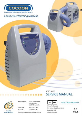
Service Manual
26 Pages
Preview
Page 1
Care Essentials
CWS4000 Cocoon Warming System Service Manual
CONTENTS 1.
INTRODUCTION ... 3
2.
OPERATION ... 4 2.1.
Unit Operation Procedure ... 4
2.2.
Symbols ... 6
3.
SAFETY PRECAUTIONS ... 8 3.1.
Danger ... 8
3.2.
Warning ... 8
3.3.
Caution ... 8
3.4.
Electromagnetic Interference ... 8
4.
PREVENTATIVE MAINTENANCE ... 9 4.1.
Cleaning ... 9
4.2.
Electrical Safety Inspection ... 9
4.3.
Performance Inspection ... 10
4.4.
Temperature Limit Thermostat Test Procedure ... 11
4.5.
Filter Replacement ... 13
5.
TROUBLESHOOTING... 14 5.1.
Warming Blanket Will Not Inflate ... 14
5.2.
Standby Indicator Will Not Light ... 14
5.3.
Equipment Repairs ... 14
6.
SCHEMATIC DIAGRAM DESCRIPTION ... 14 6.1.
Control Board... 15
6.2.
Sensor Board ... 16
6.3.
System Block Diagram ... 16
7.
BOARD COMPONENT LEGENDS ... 17 7.1.
Control Board... 17
7.2.
Sensor Board ... 18
8.
SCHEMATIC DIAGRAMS ... 19 8.1.
Control Board Schematic Diagram ... 19
8.2.
Sensor Board Schematic Diagram ... 20
8.3.
System Block Diagram ... 21
9.
PARTS LIST ... 22 9.1.
General Assembly ... 22
9.2.
Control Board... 23
9.3.
Sensor Board ... 24
9.4.
Spare Parts and Accessories ... 24
10.
WARRANTY ... 24
11.
RETURNING OF UNIT FOR REPAIR………………………………………………25
12.
SPECIFICATIONS ... 25
13.
APPROVALS ... 26
QPF 052 Revision Q
08.02.2012
Supersedes 07.11.2011
Page 2
Care Essentials
CWS4000 Cocoon Warming System Service Manual
INTRODUCTION It is a pre-requisite for all persons skilled in servicing medical devices to understand the information contained in this Manual. Read and understand this Manual and the Operator Manual and all precautions prior to servicing the Cocoon Convective Warming System. When used with Care Essentials patient warming blankets, the Care Essentials CWS4000 provides a continuous method of warming patients and is intended for preventing and treating hypothermia. The Cocoon Convective Warming System consists of a CWS4000 and a warming blanket. A connecting hose conducts heated air from the CWS4000 to the warming blanket.
Figure 1 Convective Warming System Care Essentials recommend that a program of regular routine maintenance, electrical safety and performance inspections be instituted for the CWS4000 as described in Section 3 below. The CWS4000 is a mains-powered, microprocessor-controlled device that delivers a continuous flow of temperature-controlled air through a flexible hose to the warming blanket. The temperature of the air delivered to the blanket can be set to one of six settings: ambient, 34oC, 37oC, 40oC, 43oC, or 46oC. When a temperature of 46oC is selected, the setting automatically drops to 43oC after 10 minutes. The CWS4000 will not cool the air delivered to the blanket below the ambient temperature of the room. Air is drawn into the rear of the CWS4000 and passes through a bacteriological HEPA filter. The CWS4000 includes a number of under- and over-temperature prevention systems and in a temperature fault condition it automatically shuts down and signals an alarm. This Manual presents all the relevant service information for the Care Essentials CWS4000 Cocoon Warming System. This information is provided as a service to engineering and technical personnel. This information is intended for the fair purposes of operation and maintenance of the CWS4000. It is provided as Commercial-In-Confidence material to the Care Essentials Distributor or CWS4000 owner and shall not be made available to any other organization or person without the specific written permission of Care Essentials.
QPF 052 Revision Q
08.02.2012
Supersedes 07.11.2011
Page 3
Care Essentials
CWS4000 Cocoon Warming System Service Manual
While every attempt has been made to ensure this Manual is accurate and complete, no responsibility is taken for any errors or omissions. Care Essentials has a policy of continuous product improvement and product specifications and component types are subject to change without notice. If you, as a user of this manual, have any relevant comments or questions about the CWS4000 or this Manual, your communication with Care Essentials would be welcomed. Our contact details are located on the first page of this Manual.
1.
OPERATION
2.2
Figure 2 Operator control panel
1.1.
Unit Operation Procedure
Plug the mains cable into a conventional, properly earthed 240 Volt 10 Amp mains power socket-outlet and switch it on. The green Standby indicator (B) will illuminate and the CWS4000 will beep when power is connected. Ensure that air is not prevented from entering the inlet slots at the sides by blankets or other objects. Select the desired temperature on the control panel pressing either one of the Output temperature selection buttons (E) or Ambient Temperature Output Button (C). The appropriate green or yellow light (D or F) will indicate the selected temperature setting. Another temperature may be selected at any time. The internal timer will automatically decrease the temperature setting from 46oC to 43oC after 10 minutes. This timer can be reset by momentarily selecting another setting and then re-selecting 46oC. Switch the unit off by pressing the Standby Button (A). The green Standby indicator (B) will illuminate when the unit is off. The unit will automatically switch off in an alarm condition and the green Standby indicator (B) will illuminate together with the red Fault Alarm indicator (H). QPF 052 Revision Q
08.02.2012
Supersedes 07.11.2011
Page 4
Care Essentials
CWS4000 Cocoon Warming System Service Manual
The Filter Status indicator (G) provides the user with information on remaining filter life. This indicator is interpreted as follows: Indication
Description
Steady green indicator
Filter status normal
Steady orange indicator
Filter life has reached 950 hours
Flashing orange indicator Filter life has reached 990 hours Steady red indicator
QPF 052 Revision Q
Filter life has exceeded 1000 hours and requires replacing
08.02.2012
Supersedes 07.11.2011
Page 5
Care Essentials
1.2.
CWS4000 Cocoon Warming System Service Manual
Symbols
The following symbols are used on the CWS4000:
Attention: Refer Section 2.1 Operator Manual
Dangerous voltage
Type BF applied part
Do not free hose
Single Patient Use
See Instructions for Use
NON STERILE
QPF 052 Revision Q
Non Sterile
08.02.2012
Supersedes 07.11.2011
Page 6
Care Essentials 1.3.
CWS4000 Cocoon Warming System Service Manual
Accessories
Care Essentials manufactures both Cocoon Single use and Reusable (available Australia only) Patient Warming Blankets. In addition, the CWS 4000 can be used with blankets supplied by other manufacturers. Refer to Section 8 Operators Manual for commingling information relating to the use of Cocoon warming unit and/or blankets with other manufacturer’s warming units and blankets. Use only warming blankets recommended by Care Essentials. Failure to do so may result in thermal injury Cocoon Disposable Patient Warming Blankets Features include:
Warm, soothing, cocooning design
Single use. This product is not for reuse due to the risk of cross infection
Universal inlet port ensures hose stays firmly in the blanket.
Full range of blankets:- refer www.careessentials.com.au for details
Latex free.
Cocoon Reusable Patient Warming Blankets Features include:
Technically advance smart fabric which conforms to patients body
Antistatic and non-linting
Oil and water repellent.
Universal air inlet is designed for ease of use and offers a secure fitting to all convective warming machines.
Cocoon reusable blankets are an environmental friendly alternative to disposable blankets.
Washing Instructions - please refer CWS 4000 Operator Manual, Appendix 2. Cocoon Reusable Blanket
Specific instructions for use refer to CWS 4000 Operator Manual, Appendix 2 Cocoon Reusable Blanket
Full range of blankets: refer www.careessentials.com.au for details.
Instructions for Use
Select the correct style and size of blanket.
Insert and secure the convective warming machine hose into the inlet port.
Where possible place the convective warming blanket directly against patient’s skin.
Secure the position of the blanket on the patient – tapes and ties.
Follow the convective warming machine instructions for use.
Do not use head cover unless patient is intubated and ventilated 1.3.1. Stand
An optional stand for the CWS4000 is available. QPF 052 Revision Q
08.02.2012
Supersedes 07.11.2011
Page 7
Care Essentials
CWS4000 Cocoon Warming System Service Manual
1.3.2. User Training In-service training is available from Care Essentials or nominated distributor.
2.
SAFETY PRECAUTIONS
Review the following safety precautions prior to servicing the CWS4000.
2.1.
Danger
Explosive hazard. Do not use in the presence of flammable anaesthetic agents.
Risk of electric shock. Disconnect mains power before servicing the CWS4000.
2.2.
Warning
No free hosing – use of convective warming machine without a compatible convective warming blanket may cause thermal injury.
Ensure that no direct or indirect contact is made between the patient and the communications connector located on the rear of the CWS4000.
The CWS4000 must only be opened or serviced by qualified personnel such as certified biomedical electronics technicians or certified clinical engineers familiar with repair practices for servicing medical devices, and in accordance with the Service Manual. Damage to the CWS4000 or malfunction could otherwise result.
Ensure the CWS4000 is subjected to the specified routine electrical safety and performance inspections.
In the event of excess fluid contact with the CWS4000 it is recommended that the unit be disconnected from the mains power supply and checked by qualified personnel.
Use only in accordance with Operator Manual instructions.
2.3.
Caution
Operate the CWS4000 only in the specified supply voltage range as detailed in Section 11 below.
When using an IV pole, do not mount the CWS4000 higher than 1 metre or it could tip over.
The 46oC setting is not recommended for patients who are non-responsive or with impaired circulation.
It is not recommended that the unit be operated after the filter has exceeded the specified life period.
2.4.
Electromagnetic Interference
The CWS4000 has been designed to comply with IEC 601-1-2:2004 (Medical electrical equipment – Part 1: General requirements for safety. 2. Collateral standard: electromagnetic compatibility – Requirements and tests) but this does not guarantee that other equipment in the vicinity will not be affected by the electromagnetic emissions from the CWS4000. Similarly, other equipment in the vicinity may affect the operation of the CWS4000. It is recommended that all equipment used near the CWS4000 comply with the relevant electromagnetic compatibility requirements for that equipment and to check before use that no interference is evident or disruptive. Increasing the distance between offending devices, and keeping interconnecting leads as short as possible will help reduce the effect.
QPF 052 Revision Q
08.02.2012
Supersedes 07.11.2011
Page 8
Care Essentials
3.
CWS4000 Cocoon Warming System Service Manual
PREVENTATIVE MAINTENANCE 3.1.
Cleaning
Clean the CWS4000 control panel, enclosure exterior, and hose with a soft cloth lightly dampened with a non-staining hospital disinfectant.
Clean accumulated dirt and lint from the air inlet slots using a vacuum cleaner.
3.2.
Electrical Safety Inspection
Care Essentials recommend that the CWS4000 receive regular electrical safety inspections. Information on the type and frequency of inspections may be obtained from locally published technical standards. In Australia, the relevant technical standards are:
AS3511 Technical management programs for medical devices. This standard specifies procedures required to develop equipment management programs for medical devices. Some of these include procedures for acceptance, fault management and routine testing of medical devices. This standard specifies electrical safety, essential safety and performance testing.
AS2500 Guide to the safe use of electricity in patient care. This standard provides a comprehensive guide to the safe use of electrically operated equipment used in health care facilities. Measures are detailed to provide and maintain patient and operator safety, including details of the classes of equipment and electrical installations to be used for particular medical procedures.
Programmed electrical safety inspections are essential to confirm continued operator and patient safety. Mandatory, statutory requirements for electrical safety inspections may also apply.
QPF 052 Revision Q
08.02.2012
Supersedes 07.11.2011
Page 9
Care Essentials
3.3.
CWS4000 Cocoon Warming System Service Manual
Performance Inspection
Care Essentials recommend that the CWS4000 receive at least an annual performance inspection to verify CWS4000 functions. The CWS4000 does not require adjustment or calibration. Items Required:
CWS4000 Operator & Service Manuals.
Digital Thermometer. STEP
PROCEDURE
1
If you have not already done so, read the CWS4000 Operator and Service Manuals.
2
Place the CWS4000 on a firm, level surface.
Do not connect the delivery hose to a warming blanket.
Connect the CWS4000 to mains power.
3
Familiarise yourself with the operation of the CWS4000 by operating the CWS4000 with reference to the CWS4000 Operator and Service Manuals.
4
The temperature control system is verified as follows:
Ensure the delivery hose cover is undamaged and that it covers the entire hose.
Ensure that the environmental conditions are 20 C to 22 C, 30% to 70% relative humidity, noncondensing.
Place the digital thermometer sensor in the centre of the delivery hose outlet as shown in Figure 3.
Check that the temperature of delivered air stabilises within five (5) minutes following a change in set temperature.
Check that the temperature of delivered air corresponds with the set temperature to within ±2ºC.
Note that some variation between the set temperature and temperature of delivered air is possible because of heat loss that occurs in the delivery hose. The magnitude of the heat loss will depend on the ambient temperature and the degree to which the hose is bent, longitudinally compressed or extended.
o
o
Figure 3 Delivery hose outlet showing temperature sensor position
QPF 052 Revision Q
08.02.2012
Supersedes 07.11.2011
Page 10
Care Essentials
3.4.
CWS4000 Cocoon Warming System Service Manual
Temperature Limit Thermostat Test Procedure
The CWS4000 temperature limit thermostat test is completely optional and may be performed at the discretion of those responsible for the technical management of the CWS4000. The CWS4000 temperature limit thermostat function does not require adjustment or calibration. The maximum delivered air temperature is not only limited by the control system but by two series-connected bimetallic auto-resetting thermostats. These thermostats are located in the exhaust air stream and will interrupt power to the CWS4000 should the output air temperature exceed a predetermined limit. Either of these two independently operating thermostats will remove power from the CWS4000 if the delivered air exceeds a preset high limit temperature, automatically restoring power when the thermostat temperature fails to a safe level. This test procedure may be briefly described as follows. The CWS4000 is set up with the various items required to perform the test. The CWS4000 is energised and operated at a set temperature of 46°C until it has “warmed up.” The test is commenced through a special process that switches the heater on continuously, simulating a possible fault condition. The test time and delivery hose air temperature are monitored. The test is passed if the CWS4000 is de-energised less than five (5) minutes after the test start. Note that this test will only produce a valid result if it is performed at an ambient temperature of 21°C, or greater. Items Required:
CWS4000 Operator and Service Manuals.
CWS4000 RS232 Communications Cable.
Personal Computer (PC) with a free serial communications (Com) port and a suitable Terminal program, eg HyperTerminal™, which is part of Microsoft Windows™.
Digital Thermometer with ±0.5ºC accuracy.
STEP
PROCEDURE
1
If you have not already done so, read the CWS4000 Instruction Manual and Service Manual. Read all of this procedure.
2
Place the CWS4000 on a firm, level surface.
Do not connect the PVC delivery hose to a warming blanket.
Disconnect the CWS4000 from mains power.
Locate the enclosure rear with the warning label.
Locate the small black cable socket on the top left of the enclosure rear.
Insert the cable plug into the socket. It should snap into place.
Insert the cable D-connector into a free Com port connector on the PC.
3
4
Place the digital thermometer sensor in the centre of the delivery hose outlet as shown in Figure 3 above.
5
Connect the CWS4000 to mains power.
Select the 46ºC temperature setting.
Operate the CWS4000 on the 46ºC temperature setting for at least 5 minutes prior to commencing the thermostat test.
6
While the CWS4000 is “warming up”, start the Terminal program on the PC and select the settings as follows:
Select the Com port connected to the Converter cable in Step 4 above.
Baud rate – 9600, data bits – 8, parity – none, flow control – none.
Terminal emulation – VT100, character set – ASCII.
Append line feeds to incoming line ends – enabled.
QPF 052 Revision Q
08.02.2012
Supersedes 07.11.2011
Page 11
Care Essentials
CWS4000 Cocoon Warming System Service Manual
STEP 7
8
9
PROCEDURE Follow the instructions shown on the Terminal window:
When a correct connection is established between the CWS4000 and the PC, a dot (.) is received every second.
Press the spacebar to display the root screen.
Press “T” to display the over-temperature thermostat test screen.
The 46ºC temperature setting must be selected in order for the test to proceed.
To initiate the over-temperature thermostat test, SLOWLY type, “YES” then press the Enter key. To stop the test, press any key or change the CWS4000 temperature setting.
The CWS4000 is deemed to have passed the test if a thermostat trips in less than five (5) minutes.
Confirm that the thermostat resets after several minutes, restoring power to the CWS4000.
Disconnect the CWS4000 from mains power.
Disconnect the cable from the CWS4000 and PC.
Confirm that the CWS4000 functions correctly by undertaking a performance inspection as detailed in Section 3.3 above.
QPF 052 Revision Q
08.02.2012
Supersedes 07.11.2011
Page 12
Care Essentials
3.5.
CWS4000 Cocoon Warming System Service Manual
Filter Replacement
The CWS4000 has a replaceable HEPA filter. Under normal use, replace the HEPA filter inside the CWS4000 every 1000 operating hours or 12 months, whichever occurs first. The FILTER STATUS indicator will warn of the need for filter replacement. Items Required:
CWS4000 Operator & Service Manuals.
Philips Number 1 and 2 Screwdrivers.
13 mm spanner.
HEPA filter. STEP
PROCEDURE
1
If you have not already done so, read the CWS4000 Operator and Service Manuals.
2
Place the CWS4000 on a firm, level surface.
Do not connect the PVC delivery hose to a warming blanket.
Disconnect the CWS4000 from mains power.
Locate the enclosure rear with the warning label.
Remove the seven (7) Philips head screws located around the perimeter of the enclosure rear.
Remove the enclosure rear being careful not to stress cable assemblies that run between the enclosure front and rear.
To disconnect the membrane keypad tail from the Control Board, hold the blue connector and pull. Do not pull the tail itself, as damage will almost certainly result.
Remove the nut and washer securing the HEPA filter.
Remove the old HEPA filter and discard.
Install the new HEPA filter.
Replace the nut and washer securing the HEPA filter.
Connect the CWS4000 to mains power. Exercise care, as there will be dangerous voltages present on some internal parts of the CWS4000.
Read and note the run hour meter on the control board. Hour digits are sequentially displayed followed by an “h”, “r”, and a pause.
Mark the HEPA filter with the hour meter reading and date of replacement.
Record these figures in the CWS4000 service record.
Reset the filter life 1000-hour counter by pressing and holding the switch in front of the hour meter display. A steady green FILTER STATUS indicator and a long beep will indicate the successful reset of the 1000-hour counter.
Disconnect the CWS4000 from mains power.
3
4
5
6
Replace the rear panel by reversing step 5 above.
7
Confirm that the CWS4000 functions correctly by undertaking a performance inspection as detailed in Section 3.3 above.
QPF 052 Revision Q
08.02.2012
Supersedes 07.11.2011
Page 13
Care Essentials
4.
CWS4000 Cocoon Warming System Service Manual
TROUBLESHOOTING 4.1.
Warming Blanket Will Not Inflate
Make sure the CWS4000 is plugged in to an energized mains power socket-outlet.
Check both ends of the delivery hose for proper connection.
Check the delivery hose and warming blanket inlet for kinks.
Check that there are no obstructions to the air inlet slots.
Check the warming blanket for damage. If air is flowing from the hose, try another warming blanket. Small rips or tears in the warming blanket may be temporarily repaired with adhesive tape.
Request qualified service personnel check for a clogged or dirty filter.
Check for fault alarm.
4.2.
Standby Indicator Will Not Light
Extremely high storage temperatures (such as those found motor cars on hot summer days) can cause the temperature limit thermostats in the CWS4000 to actuate. Should this occur, the STANDBY indicator will fail to light when the CWS4000 is connected to mains power. If this occurs, simply wait for the CWS4000 to cool down and eventually the thermostats will automatically reset and the STANDBY indicator will light.
Request qualified service personnel check for blown mains power fuses.
4.3.
Equipment Repairs
Repairs to the CWS4000 should be performed by qualified personnel such as certified biomedical electronics technicians or clinical engineers familiar with repair practices for servicing medical devices, and in accordance with the CWS4000 Service Manual. Damage to the CWS4000 or malfunction may otherwise result.
5.
SCHEMATIC DIAGRAM DESCRIPTION
This section describes the CWS4000 schematic diagrams. Reference should be made to the printed circuit board (PCB) component legend contained in Section 6 and the schematic diagrams contained in Section 7 below. The following should assist with the interpretation of the Schematic Diagrams:
The schematic diagrams are organised in a flat structure.
Electrical connectivity is shown by continuous wires or net labels on partial wires.
Net labels (signal names) are prefixed with a forward slash when they are asserted with logic “0” (eg: /SIGNAL).
The CWS4000 Control Board implements the following functions:
Microcontroller.
RS232 transceiver (Control Board revision E and later).
Microcontroller reset circuit.
Fan control.
Heater control.
QPF 052 Revision Q
08.02.2012
Supersedes 07.11.2011
Page 14
Care Essentials
CWS4000 Cocoon Warming System Service Manual
LED display drivers.
Run hour meter display.
Filter life hour counter reset switch.
Buzzer.
Power supplies.
The CWS4000 Sensor Board implements the following functions:
Digital temperature sensor.
Temperature limit thermostats.
The more important of these functions are elaborated below.
5.1.
Control Board
Microcontroller The microcontroller (U1) integrates a number of functions:
CPU.
Program ROM.
RAM.
EEPROM.
Interrupt controller.
External interrupts.
Counter/Timers.
Watchdog timer.
Digital Input/Output ports.
The microcontroller performs the following functions:
Monitors the exhaust air temperature through the digital temperature sensor.
Monitors the push-button switches.
Controls the display and buzzer drivers.
Controls the heater and fan.
The microcontroller ROM is factory programmed with the application software program. The software program contained in the microcontroller ROM is subject to copyright. In the event of a microcontroller fault, Care Essentials must fit a replacement part. Reset Circuit When the microcontroller is reset either by power-on or by the watchdog timer:
Digital Input/Output ports 0 – 3 go high.
Signal /FAN goes low switching on the fan relay. The fan blower is switched on.
Signal /HEAT goes high switching off the heater triac. The heater is switched off.
QPF 052 Revision Q
08.02.2012
Supersedes 07.11.2011
Page 15
Care Essentials
CWS4000 Cocoon Warming System Service Manual
Thus the reset process implements a safety strategy to prevent the fan blower being turned off with the heater being turned on. Power-On Reset Following power-on capacitor (C3) charges from zero to +5V (VCC) through resistor (R1) connected to ground. This causes the Reset input of the microcontroller to be momentarily asserted high. The microcontroller type used on Control Board revision E and later has an internal power-on reset circuit and capacitor (C3), resistor (R1) and diode (D1) are not fitted. Watchdog Reset The microcontroller watchdog timer is incremented regularly by the microcontroller hardware. When a watchdog timer overflow occurs the microcontroller is reset. To prevent such a system reset the microcontroller watchdog timer is reloaded before it overflows by the application software program. If the microcontroller suffers a hardware or software malfunction, the application software program will fail to load the microcontroller watchdog timer. This failure will produce a system reset on overflow thus preventing the microcontroller from running out of control. This prevents a potentially hazardous situation from occurring.
5.2.
Sensor Board
Digital Temperature Sensor The temperature sensor (U1) is controlled by and communicates with the Control Board microcontroller (U1). Temperature Limit Thermostats The maximum air temperature is not only limited by the control system but by two seriesconnected bimetallic auto-resetting thermostats. These thermostats are located in the exhaust air stream and will interrupt power to the CWS4000 should the output air temperature exceed a predetermined limit. The temperature limit thermostat function does not require adjustment or calibration.
5.3.
System Block Diagram
The System Block Diagram shows the general electrical connectivity between the various CWS4000 electrical and electronic subassemblies:
Power inlet module including EMI filter and fuses.
Temperature limit thermostats.
Heater.
Fan blower.
Control Board.
Sensor Board.
Communications connector.
Before removing any of the connections between the electrical and electronic subassemblies, make a careful note so that these may be correctly reinstated. Incorrect connections could compromise patient safety and/or damage the CWS4000. The System Block Diagram is presented as an aid to understanding the CWS4000 and does warrant extensive discussion.
QPF 052 Revision Q
08.02.2012
Supersedes 07.11.2011
Page 16
Care Essentials
6.
CWS4000 Cocoon Warming System Service Manual
BOARD COMPONENT LEGENDS 6.1.
Control Board
Not fitted when U1 is AT89S8253 Not fitted
QPF 052 Revision Q
08.02.2012
Supersedes 07.11.2011
Page 17
Care Essentials
7.
CWS4000 Cocoon Warming System Service Manual
SCHEMATIC DIAGRAMS 7.1.
QPF 052 Revision Q
Control Board Schematic Diagram
08.02.2012
Supersedes 07.11.2011
Page 19
Care Essentials
7.3.
QPF 052 Revision Q
CWS4000 Cocoon Warming System Service Manual
System Block Diagram
08.02.2012
Supersedes 07.11.2011
Page 21
Care Essentials
8.
CWS4000 Cocoon Warming System Service Manual
PARTS LIST 8.1.
General Assembly
MANUF.
PART NO
DESCRIPTION
QTY
Care Ess
CWS-CTLE
Control Board
1
Care Ess
CWS-SOTE
Sensor Board
1
Care Ess
Membrane Keypad
1
Care Ess
Cable Assembly, Active, Power Entry – Thermal Switch
1
Care Ess
Cable Assembly, Active, Thermal Switch – Control Board
1
Care Ess
Cable Assembly, Active, Thermal Switch – Thermal Switch
1
Care Ess
Cable Assembly, Neutral, Power Entry – Control Board
1
Care Ess
Cable Assembly, Ground, Power Entry – Baffle
1
Care Ess
Cable Assembly, Fan
1
Care Ess
Heater Assembly
1
Care Ess
Cable Assembly, Communications
1
Bussman
S504 6.3A
Fuse, Time Lag (T), 20x5mm, 250V, 6.3A
2
Schurter
5220.0643.1
Power Entry Module, Fuseholder, Filter, Panel Mount, Snap-In
1
Harris
V275LA10
MOV, 275Vac
2
Brady
WLB02
Label, Earth Symbol 12.5x12.5mm
1
QPF 052 Revision Q
08.02.2012
Supersedes 07.11.2011
Page 22
Care Essentials
8.2.
CWS4000 Cocoon Warming System Service Manual
Control Board
CIRCUIT DESIG.
MANUF.
PART NO
DESCRIPTION
(F1)
Multicomp
MCHTE15M
Fuseholder, 5x20mm, PCB Mount
1
(F1)
Multicomp
MCHTE150M
Fuseholder Cover, 5x20mm
1
(Q1, U5)
Any
Screw, Zinc-Plated Steel, Pan-Head, M3x6
2
(Q1, U5)
Any
Nut Zinc-Plated Steel, M3
2
(Q1, U5)
Any
Washer, Internal S/proof Zinc-Plated Steel, M3
2
(Q1)
Bergquist
Sil-Pad K-10
Thermally Conductive Pad, TO-220
1
BZ1
Star
TMB12
Buzzer, Miniature, 8-16Vdc
1
C10
Philips
47nF 275Vac
Capacitor, Metallised Polypropylene, Class X2, 275Vac, 0.6"
1
C11, 12
Philips
470nF 275Vac
Capacitor, Metallised Polypropylene, Class X2, 275Vac, 0.9"
2
C1-2
Philips
5pF
Capacitor, Ceramic, 50V, 0.2" Pitch
2
C6, 7, 9
Rubycon
1uF 50V
Capacitor, Electrolytic, 50V, Radial, 0.2" Pitch
3
C4
Multicomp
2200uF 25V
Capacitor, Electrolytic, 25V, Radial, 0.2/0.3" Pitch
1
C5, 8,1318 D2-3
Multicomp
100nF 50V
Capacitor, Ceramic, Z5U, 50V, 0.2" Pitch
8
Multicomp
SA5A
Transient Voltage Suppressor, 5V 500W
2
DB1
IR
DF04
Diode, Bridge, 400V 1A (4 Pin Plastic DIP)
1
F1
Bussman
S504 63mA
Fuse, Time Lag (T), 20x5mm, 250V, 63mA
1
F2
Philips
2322 660 57693
Thermistor, PTC, Overload Protection, Trip 115mA
1
HS1
Thermalloy
7025B-MT
Heatsink, TO-220
1
L1
Timonta
DFSG1-30-6/A
Choke, Saturating, 6A
1
ND1
Agilent
HDSP-7505
Display, LED, 7-Segment, Common-Cathode, HE-Red, 0.3"
1
P1
Phoenix
Header, PCB Mount, 6 Way, 0.2" Pitch
1
P2
Molex
MSTBA25/6G508 22-27-2081
1
P3
AMP
3-103321-0
Header, Square Pin, Friction Lock, PCB Mount, 8 Way, 0.1" Pitch Header, Square Pin, PCB Mount, 19 Way, 0.1" Pitch
P4
Molex
22-27-2031
1
Q1
SGS
BTA12-600BW
Header, Square Pin, Friction Lock, PCB Mount, 3 Way, 0.1" Pitch Triac, 600V, 12A, Snubberless (TO-220)
R2-6
Multicomp
680R
Resistor, 0.25W 1%
5
RLY1
Schrack
RTB14012
Relay, SPDT, 12Vdc Coil, 240Vac 12A Contacts
1
RN1-3
Bourns
4610X-102 472
Resistor Network, 9x4K7 Resistor with Common (10 Pin SIP)
3
RN4, 5
Bourns
4116R-001 681
Resistor Network, 8x680R Resistors (16 Pin Plastic DIP)
2
S1
Bourns
7906H-001-000
Switch, Pushbutton, PCB, SPNO, 6x6mm
1
T1
Polykom
750718
Transformer, Mains Step-Down, 240V:9V:9V 7VA
1
U1
Atmel
Microcontroller, 8-Bit, 12K Flash, 24MHz (40 Pin Plastic DIP)
1
U2-3
Any
AT89S825324PC UDN2981A
Driver, Darlington, 8-Channel (18 Pin Plastic DIP)
2
U4
Any
ULN2803
Driver, Darlington, 8-Channel (18 Pin Plastic DIP)
1
U5
National
LM7805CT
Voltage Regulator, Linear, Positive, +5V (TO-220)
1
U6
Fairchild
H11L1M
Optocoupler, Schmitt Trigger Output
1
U7
Fairchild
MOC3021-M
Optocoupler, Triac Driver
1
V1
Harris
V275LA10
MOV, 275Vac
1
X1
IQD
L108K
Crystal, 11.0592MHz, (HC49/4H Can)
1
QTY
Note: R1, D1 and C3 are not fitted when U1 is an AT89S8253-24PC. QPF 052 Revision Q
08.02.2012
Supersedes 07.11.2011
Page 23
1
1