deSoutter
CC5A Cast Saw and Extraction System Operating Instructions Ver 7.5
Operating Instructions
16 Pages
Preview
Page 1
Operating Instructions
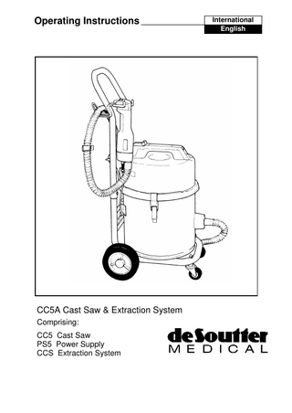
CC5A Cast Saw & Extraction System Comprising: CC5 Cast Saw PS5 Power Supply CCS Extraction System
International English
De Soutter Medical Cast Saw & Extraction System Index
Item
Page
Warnings and Safety Rules ... 3 Product Description ... 3 System Assembly... 4 System Controls ... 5 Operation ... 6 Cutting Technique ... 6 Cleaning and Maintenance... 7 Extractor Bag Replacement ... 7 Fault Finding ... 8 Service Information ... 8 Explanation of Symbols ... 8 Technical Description ... 9 Supplied Accessories ... 10 Optional Accessories ... 10 Conditions for Transport & Storage ... 10 Equipment Part Number Details ... 10 Service Diagram ... 11 Saw Blade Chart ... 12 Guarantee & Liability ... 13
2
Warnings & Safety Rules WARNING!: THIS EQUIPMENT MUST BE EARTHED! Danger!: Possible explosion hazard if used in the presence of flammable anaesthetics. Only permit trained personnel to use this equipment. Do not connect the equipment to the mains supply until all the instructions have been studied. Always check that the voltage stated on the identification plate corresponds with the electrical supply. Carefully inspect all equipment and accessories before use. Do not operate the equipment if it appears damaged or incorrectly installed. Always test the equipment prior to use, and check for malfunction or rapid temperature rise. Do not use suspect or damaged equipment. Always use eye protection when cutting to prevent injury from flying debris. Always ensure that no loose articles can be caught by the moving parts of the equipment. Always disconnect the equipment from the electrical supply when cleaning, changing accessories or when not in use. Always allow the equipment to stop before removing from the cutting site. Do not immerse the equipment in fluids. Do not drop the equipment. Do not clean in an ultrasonic cleaner. Do Not leave the extractor unattended when it is switched on.
Product Description The De Soutter Medical CC5A consists of four items: • CC5 Saw: The De Soutter Medical model CC5 is a low voltage two speed saw designed for the safe removal of surgical casts. • PS5 Power Supply: The PS5 power supply provides the CC5 saw with low voltage electricity. It is located under the CCS debris drum. • CCS Extractor: The CCS extractor provides a powerful suction at the cutting site, removing fumes, dust and debris generated in the cast cutting process. These particles are ducted from the cutting site through the extraction hose and are contained in the disposable bag in the debris drum. • Extraction Hose Kit: The hose kit provides the hose and other accessories required for assembly of the CCS5 system.
3
System Assembly Mains Supply Lead If an unsuitable plug is fitted to the mains lead, remove and destroy this plug before disposal. The wires in the mains lead are coloured in accordance with the following code: Blue - Neutral Brown - Live Green/Yellow - Earth Connect the wires in the mains lead to a suitable plug as follows: Blue wire to the terminal marked either letter N or coloured blue or black. Brown wire to the terminal marked either letter L or coloured brown or red. Green/Yellow wire to the terminal marked either letter E or coloured green. Ensure that the correct fuse is fitted to protect the equipment: refer to the Technical Description for details of which fuse is required. Extractor and Power Supply The system may be supplied in two different formats: 1. PS5 power supply assembled to CCS extractor chassis. • Disconnect the debris drum from the chassis and insert the CC5 saw power cable into the PS5 power supply socket. Insert the cable into the cable restraint and latching clip. Replace the debris drum and re-connect the power supply plug into the socket on the powerhead. 2. PS5 power supply not assembled to CCS extractor chassis. • Disconnect the debris drum from the chassis, and pass the power supply cable through the rear box tray aperture. Secure the tray with the nuts and bolts provided. Locate the power supply by sliding it backwards on the tray retainers, and secure it with the small self tapping screw. Saw & Hose: • Attach the metal connector of the extraction hose assembly into the rear of the CC5 saw and the other end on to the vacuum inlet spigot on the debris drum. • Secure the CC5 power cable to the hose with the clips provided. Handle: • Assemble the handle to the chassis and secure with the nuts and bolts provided. Refer to the diagram on page 7 of this manual. Saw: • Attach the blade of choice to the tool output shaft, secure the clamp screw and tighten with the hexagon key provided. Always check the condition of the blade before use. The blade may be repositioned up to five times, therefore always presenting an unused section. 4
System Controls
Main On/Off Switch: Located at the front of the extractor powerhead handle.
Extractor Controls: Automatic: Set the automatic/manual switch to automatic. The extractor will now operate when the tool is switched on, and purge itself for a few seconds after the tool is switched off. Manual: Set the automatic/manual switch to manual. The extractor may now be operated independently from the saw. HI/ LO Extractor Suction: Select the desired suction level with the HI/ LO suction control. LO suction is normally adequate for general cast cutting, and is much quieter.
Power Supply Controls: The power supply is operated by the illuminated green switch at the rear.
Saw Controls: Operate the saw using the rear mounted On/Off switch (this switch remotely controls the extractor when set in Automatic mode). Select the desired saw speed by setting the switch on the rear of the saw to either (low) or (high). The saw cannot be operated without the extractor.
5
Operation System Operation Set the controls for the extractor suction and saw speed to the desired settings. Switch the PS5 power supply ON. This switch may be left ON permanently. Switch the extractor mains switch ON. In Automatic mode, the system will now be controlled from the On/Off switch on the saw. Cutting Technique Before use, the operator should handle the saw and determine the most convenient grip position. Do not exert excessive working pressure - allow the blade to cut at it’s own rate. Excessive pressure will overload the motor, without increasing cutting efficiency, and will cause the overload to trip. If this occurs reset the overload by pushing the overload button on the power supply. Caution: Excessive cutting pressure will also cause the blade to overheat which may result in injury to the patient. Likewise badly worn blades will generate excessive heat therefore the blades should be inspected and replaced regularly. A new or repositioned blade will improve cutting efficiency. Reduce vibration and temperature of the blade when cutting. Make the first cut both downwards and slightly sideways, at approximately 30 degrees, in order to keep one side of the blade out of contact with the cast. This will allow the operator a greater sense of feel when the blade breaks through. After the first cut, all cuts should be made straight down into the cast. The cutter should be lifted slightly and moved sideways; the second cut can then be taken straight down, the operator feeling the break through quite easily. Cutting can then proceed in a series of downward cuts, lifting and moving sideways progressively. The blade may touch soft mobile tissue momentarily without harm under a light pressure, however it should never be permitted to be in contact with the skin for any length of time.
6
Cleaning and Maintenance The system should be checked visually after each use for each of the following: • Condition of the electrical cables, for wear or abrasion. • Excessive build up of plaster dust in the hood. • The blade for wear and the blade retainer for tightness. • The system as a whole for damage. Never use any equipment you suspect to be damaged. Periodically check the Extractor filters and bag for excessive contamination. Periodic technical maintenance is not required. Cleaning Use suitable disinfecting and cleaning materials as per local decontamination guide lines.
Extractor Bag Replacement and Filter Cleaning For maximum efficiency replace the paper dust bag as soon as the suction performance decreases. Powerhead
To gain access to the dust bag, release the two powerhead latches and remove the powerhead. Lift out the two permanent filters, and remove the dust bag by sliding the cardboard collar from the inlet spigot. Dust bag replacement is carried out in the reverse sequence.
Microfilter cover
Permanent Filters
If after prolonged use the permanent filters appear excessively contaminated, rinse them thoroughly in luke warm water and allow them to dry naturally before use.
Paper Dust Bag Part No. 602763 (Pack of 10)
The Microfilter is not a user serviceable item and can only be replaced by qualified technical personnel.
Debris drum
7
Fault Finding Unit will not start: Check the condition of the fuses and the overload protectors, located: • On the power supply - 2 fuses and 1 overload protector. • On the extractor powerhead handle. To release the built in fuses, depress and twist the fuseholder. Withdraw the fuse in its holder, and inspect and replace as necessary. Reset the overload by pushing the overload button on the power supply. Unit stops in use: Wait five minutes and see if the thermal overloads reset. These thermal overloads are located in the extractor and in the power supply, and operate automatically. Tool cuts slowly: Check the condition of the blade. Adjust and replace the blade as required. Extractor is noisy and suction is poor: Check the paper debris bag and the filters. Change the bag or clean the filters as required. If any problem persists then consult De Soutter Medical Ltd. Service Instructions
See the exploded diagram on page 11 of this manual. This equipment is only user serviceable for parts and assemblies described in the diagram. Any other repairs can only be carried out at an Authorised De Soutter Medical Service Centre. If there are any service queries, including further information or replacement parts, contact De Soutter Medical. Explanation of Symbols
~
l O
Alternating Current (a.c.) Direct Current (d.c.) Class II Type of protection against electric shock.
or
Power On Power Off Refer to Operating Instructions
Type B degree of protection against electric shock
Do Not Immerse
Saw Low Speed
Saw High Speed
Fuse
Serial No. First two numerical digits indicate Year of manufacture.
SN 10/00500 8
Technical Description CC5 Saw Oscillating Frequency, normal speed Oscillating Frequency, high speed Power Consumption Motor Protection
11 900 cycles/ min. 15 200 cycles/ min. 100VA Overload cutout, manual reset (On PS5 Power Supply)
PS5 Power Supply Supply Voltage Supply Frequency Power Output Fuses
230V~ or 120V~ or 100V~ 50 - 60Hz 100 VA 1 x F10A and: 1 x T2A 230V~ 1 x T4A 100V~ & 120V~
Note: The CC5 saw can only be used with the PS5 power supply. CCS Extractor Unit Supply Voltage: Supply Frequency: Vacuum Unit Amperage:
230V~ or 100-120V~ 50 - 60Hz 5 Amp(230V) 7 Amp (100V-120V) 1000W 2500mm Water Gauge 99.997% >0.5um 2 x T6.3A (230V) 2 x T15A (100V-120V)
Motor Power: Suction: Filtration: Fuses:
On/Off switching: Auxiliary Socket Load: Type of protection against electric shock: Degree of protection against electric shock: Degree of protection against harmful ingress of liquids: Mode of Operation: CC5 Saw and PS5 Power Supply Type of Protection against electric shock
Automatic or Manual 1.5A max. Class 1 - Earthed. -Type B Ordinary Continuous.
Class ll - double insulated.
CC5A Complete System - CC5 Saw, PS5 Power Supply & CCS Extractor Degree of Protection against electric shock - Type B Degree of protection against harmful ingress of liquids Ordinary Mode of Operation Continuous
9
Supplied Accessories. Description Saw Blade Hexagon Key
Part No. 6250 204903
Optional Accessories. Description Paper Debris bag (pack of 10) Saw Blades
Part No. 602763 Refer to Chart on page 12
Conditions for Transport & Storage Temperature: Relative Humidity: Atmospheric Pressure:
-20ºC to +40ºC 90% maximum. 1.5 Atmospheres max.
Equipment Part Number Details Model No.
Part. No.
Description
CC5
1270554
Cast Saw
PS5 230V Complete.
609053
Power Supply
PS5 120V Complete.
609983
Power Supply
PS5 100V Complete.
609063
Power Supply
CCS 230V UK Plug
1190
Extractor Unit
CCS 230V Euro Plug
7020
Extractor Unit
CCS 100-120V
7140
Extractor Unit
6400
Extractor Hose Kit
10
Saw Blades
Part No. 1060
Dia. 80
Type Circular PTFE Coated
3950
64
Circular TiN Coated
6230
44
Circular PTFE Coated
6240
50
Circular PTFE Coated
6250
64
Circular PTFE Coated
6260
80
Segment PTFE Coated
7310
64
Circular Diamond Coated
7320
80
Circular Diamond Coated
7960
64
Circular, Stainless Steel
12
Guarantee & Liability De Soutter Medical guarantees all instruments, attachments and accessories to be free from defects in material and workmanship for one year from the date of purchase. De Soutter Medical is not liable by warranty or otherwise in the case of any of the following: • Abuse, misuse or use in other than the designed purpose; • Alteration or unauthorised repair; • If the product has not been used in a reasonable manner and in full compliance with the written instructions. This guarantee does not affect your Statutory Rights in accordance with 1999/44/EEC Service Information All powered instruments should be periodically checked and cleaned: in general, annual servicing is recommended for normal use. User service information is available upon request. Service and repair is also available from your nearest De Soutter Medical Authorised Service Centre.
Repair Service To return an instrument for repair: Record the serial number of the instrument being returned. Enclose a brief statement describing the reason for returning the instrument. Enclose the purchase order number for the instrument if warranty is being claimed. It may be helpful also to include a contact name. Wrap the instrument to prevent damage during shipment and send to the address below. Please ensure that the tool is properly cleaned and disinfected before returning it for service.
13