deSoutter
CCS Dust Extractor Operating Instructions Ver 3.3
Operating Instructions
8 Pages
Preview
Page 1
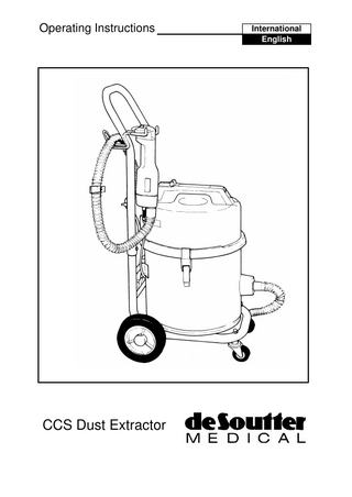
Operating Instructions
CCS Dust Extractor
International English
Electric Cast Saw Dust Removal System Warnings & Safety Rules WARNING!: THIS EQUIPMENT MUST BE EARTHED! Danger!: Possible explosion hazard if used in the presence of flammable anaesthetics. Only permit trained personnel to use this equipment. Do not connect the equipment to the mains supply until all the instructions have been studied. Always check that the voltage stated on the identification plate corresponds with the electrical supply. Carefully inspect all equipment and accessories before use. Do not operate the equipment if it appears damaged or incorrectly installed. Always test the equipment prior to use, and check for malfunction or rapid temperature rise. Do not use suspect or damaged equipment. Always use eye protection when cutting to prevent injury from flying debris. Always ensure that no loose articles can be caught by the moving parts of the equipment. Always disconnect the equipment from the electrical supply when cleaning, changing accessories or when not in use. Always allow the equipment to stop before removing from the cutting site. Do not immerse the equipment in fluids. Do not drop the equipment. Do not clean with liquid or disinfectants. Do not clean in an ultrasonic cleaner. Do Not leave the extractor unattended when it is switched on.
Description The De Soutter Medical CCS extractor provides a powerful suction at the cutting site, removing fumes, dust and debris generated in the cast cutting process. These particles are ducted from the cutting site through the extraction hose and are contained in the disposable bag in the debris drum.
1
Assembly Cast Cutter Power Cable: The vacuum unit power head is supplied with one IEC60320 power socket at the rear. If an IEC60320 plug is not fitted to the cast cutter cable, connect the wires as follows: Brown wire to the plug terminal marked L or coloured red. Blue wire to the plug terminal marked N or coloured black.
Handle: Assemble the handle to the chassis and secure with the nuts and bolts provided.
Extraction Accessory Kit: Assemble the extraction hood to the cast cutter, the elbow to hood and the hose end with metal sleeve to the elbow. Secure the cast cutter cable to the hose with the clips provided. Remove vacuum unit from the chassis by releasing the rear clip. Position the cast cutter cable into the 4 clips on the chassis and twist the clip latches to retain. Replace the vacuum unit, secure by fastening rear clips and insert cast cutter plug into power head socket. Attach the hose to the vacuum inlet and screw into drum spigot.
Operation Plug the power cable into the mains supply. Automatic: Switch the extractor mains switch on and set the automatic/manual switch to automatic. The extractor will now operate when the tool is switched on, and will turn off a few seconds after the tool is switched off. Manual: Switch the extractor mains switch on and set the automatic/manual switch to manual. The extractor and saw may now be operated independently.
2
Cleaning Unplug vacuum unit from electrical supply and wipe external parts with a damp cloth.
Extractor Bag Replacement and Filter Cleaning For maximum efficiency replace the paper dust bag as soon as the suction performance decreases. Powerhead
To gain access to the dust bag, release the two powerhead latches and remove the powerhead. Lift out the two permanent filters, and remove the dust bag by sliding the cardboard collar from the inlet spigot. Dust bag replacement is carried out in the reverse sequence. If after prolonged use the permanent filters appear excessively contaminated, rinse them thoroughly in luke warm water and allow them to dry naturally before use. The Microfilter is not a user serviceable item and can only be replaced by qualified technical personnel.
Microfilter cover
Permanent Filters
Paper Dust Bag Part No. 602763 (Pack of 10)
Debris drum
Fault Finding Unit will not start: Check the condition of the supply fuse and the built in fuse adjacent to the mode switch. To release the built in fuses, depress and twist the fuseholder. Withdraw the fuse in its holder, and inspect and replace as necessary. Unit stops in use: Wait five minutes and see if the thermal overload resets. If it does not, check the fuses. If any problems persist then consult De Soutter Medical Ltd.
3
Optional Accessories & Replacement Filters
Paper Debris bag (pack of 10)
Part No. 602763
Primary Permanent Filter
603203
Secondary Permanent Filter
603213
Equipment Part Number Details Model No.
Part. No.
CCS 230V UK Plug
1190
CCS 230V Euro Plug
7020
CCS 100-120V CCS 230V Australian Plug
7140 9490
Technical Description Supply Voltage:
220-240V a.c. or 100-120V a.c.
Supply Frequency:
50 - 60Hz
Vacuum Unit Amperage:
5 Amp(220-240V) or 7 Amp (100-120V)
Motor Power:
1100W
Suction:
2500mm Water Gauge
Filtration:
99.997% >0.5µm
Fuses:
2 x T6.3A (220-240V) or 2 x T15A (100-120V)
Sound Level:
58dB(A)
On/Off switching:
Automatic or Manual
Auxiliary Socket Load:
1.5A max.
Type of protection against electric shock:
Class 1 - Earthed.
Degree of protection against electric shock:
Type B
Degree of protection against harmful ingress of liquids:
Ordinary
Mode of Operation:
Continuous
4
Explanation of Symbols
l
Power On
O
~
Alternating Current (a.c.) or
Type B degree of protection against electric shock SN 10/00500
Power Off Refer to Operating Instructions Do Not Immerse
Serial No. first Two numerical Digits indicate manufacture.
year
of
Repair Information For service and repair please contact your nearest De Soutter Medical Authorised Service Centre. To return an instrument for repair: • Record the serial number of the instrument being returned. Enclose a brief statement describing the reason for returning the instrument. • Enclose the purchase order number for the instrument if warranty is being claimed. It will be helpful to include a contact name. • Pack the instrument securely and send to the address below. Please ensure that the instrument has been properly decontaminated and sterilized.
Guarantee & Liability De Soutter Medical guarantees all instruments, attachments and accessories to be free from defects in material and workmanship for one year from the date of purchase. De Soutter Medical is not liable by warranty or otherwise in the case of any of the following: • Abuse, misuse or use in other than the designed purpose; • Alteration or unauthorised repair; • If the product has not been used in a reasonable manner and in full compliance with the written instructions. This guarantee does not affect your Statutory Rights in accordance with 1999/44/EEC
Conditions for Transport & Storage Relative Humidity Temperature Atmospheric Pressure
90% Max -20ºC to 40ºC 1.5 Atmospheres Max 5
United Kingdom De Soutter Medical Limited Halton Brook Business Park Weston Road Aston Clinton Bucks HP22 5WF United Kingdom Tel: +44 (0)1296 634 000 Fax: +44 (0)1296 634 033 Email: [email protected] Internet: http://www.de-soutter.com
Australia De Soutter Medical Australia Pty Ltd 2/12-14 Apollo Drive Hallam Victoria 3803 Australia Tel: +61 (0) 3 9702 4441 Fax: +61 (0) 3 9702 4484 Email: [email protected]
Österreich De Soutter Medical Austria Zweigniederlassung Österreich Dietrichsteingasse 10 A-3400 Klosterneuburg Österreich Tel: +43 (0) 676 96 71 770 Fax: +43 (0) 2243 21 656 Email: [email protected]
Belgium De Soutter Medical Belgium In De Bruel 30 3620 Lanaken Belgium Tel: +32 (0) 89/47 15 37 Fax: +32 (0) 89/70 12 19 Email: [email protected]
France De Soutter Medical France 949 Avenue Parc des Expositions 33260 La Teste de Buch France Tel: +33 (0) 5 56 54 89 36 Fax: +33 (0) 9 70 61 37 60 Email: [email protected]
Deutschland De Soutter Medical Germany Niederlassung Deutschland Kladenfloss D-66625 Nohfelden Germany
Italia De Soutter Medical Italia Palazzo Marco Polo II Girasole 20084 Lacchiarella Milano Italia Tel: +39 (0) 2 9009 4098 Fax: +39 (0) 2 9009 2673 Email: [email protected]
Tel: Fax: Email:
+49 (0) 68 52-99 12 46 +49 (0) 68 52-99 12 47 [email protected]
Ref:1157 en_gb 3.3