deSoutter
MULTIDRIVE MCX-500 Operating Instructions Ver 5.2
Operating Instructions
32 Pages
Preview
Page 1
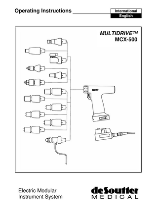
Operating Instructions
International English
MULTIDRIVE™ MCX-500
Electric Modular Instrument System
DE SOUTTER MEDICAL MCX INSTRUMENT SYSTEM Index Item
Page
Section 1: General Instructions Warnings and Safety Rules Product Description Mains Supply Reprocessing Instructions Sterilization Accessory Part Number Details
2 2 2 3 3 6
Section 2: MCX System Assembly Setting Up the Battery System Charging the Batteries Testing the Batteries Setting Up the Corded System Battery/ Module Connection Battery/ Module Removal Attachments Part Number Details
7 7 8 9 11 12 13 13 14
Section 3: MCX-500 Handpiece Controls
15 15
Section 4: MCX System Attachments DX-500 Drill Attachments RX-500 Standard Reamer and HX-500 High Torque Reamer Attachments SX-500 Sagittal Saw Attachment CX-500 Reciprocating Saw Attachment OX-500 Oscillating Drill Attachment WX-500 Wire Driver Attachment MX-500 Mini Sagittal Saw KX-500 Sagittal Saw Attachment
16 16 17 18 19 20 21 23 24
Section 5: System Fault Finding Handpiece fault finding Battery & Charger fault finding Corded System fault finding
25 25 26 27
Conditions for Transport & Storage System Technical Description Explanation of Symbols Service Information Repair Information Guarantee and Liability
27 28 29 30 30 30
0120
SECTION 1: GENERAL INSTRUCTIONS Warnings & Safety Rules Failure to follow these instructions may result in serious injury to the patient or operating staff. Do not attempt to use the equipment until all the instructions have been studied and understood. WARNING! THIS EQUIPMENT MUST BE EARTHED! Never permit untrained personnel to use this instrument system. Always check that the voltage stated on the identification plate corresponds with the electrical supply. Always ensure the correct rated fuses are fitted to either the battery charger or power supply. Always inspect all equipment and accessories before use. Do not use suspect, damaged or worn equipment. Always ensure accessories are correctly connected to the handpiece before use. Always set the instrument trigger mode selector to the SAFE position when changing accessories or when not in use. Always use eye protection when cutting to prevent injury from flying debris. Do not allow loose articles to be caught by the moving parts of the instrument. Never drop the instrument or it’s accessories; always handle with extreme care. Always allow the instrument to stop before removing from the surgical site. Only clean and sterilize the instrument and accessories as directed in these instructions. Do not immerse the instrument in fluids. Always use Stericut or De Soutter Medical approved accessories. Product Description The MCX system is a modular electric instrument system for large bone and trauma surgery, which is used with a rechargeable battery pack or low voltage corded power. The system consists of: • MCX-500 Handpiece: The MCX-500 Handpiece features a powerful reversible motor which acts as the powerplant for the MCX system. The handpiece may be fitted with the following attachments: • DX-500 Drill Attachments • RX-500 Standard Reamer Attachments • HX-500 High Torque Reamer Attachments • SX-500 Sagittal Saw Attachment • CX-500 Reciprocating Saw Attachment • OX-500 Oscillating Drill Attachment • WX-500 Wire Driver Attachment • MX-500 Mini Sagittal Saw • KX-500 Sagittal Saw Attachment Battery Power: • SBX-500 • BCX-500
Battery Pack Battery Charger
Low Voltage Corded Power: • CMX-600 Power Module • PS-600 Power Supply
2
Mains Supply The mains equipment in this system are fitted with IEC 60320 inlets. For details of suitable cordsets to use with this equipment, refer to the Part Number details at the end of this manual. Reprocessing Instructions Warnings: Limitations on reprocessing:
The following reprocessing instructions refer to the MCX-500 handpiece, its surgical tool attachments, sterile battery pack and corded power module only. Do not wash or sterilize the PSX-500 Power supply, BCX500 Battery Charger or mains cord. Refer to separate cleaning and maintenance instruction following this section for more detail. Do not immerse the handpiece in water other than when automatic reprocessing. Do not exceed temperatures 140 C. Do not clean any part of the equipment in an ultrasonic cleaner. Long narrow cannulations and blind holes require particular attention during cleaning. Repeated processing has minimal effect on these instruments. End of life is normally determined by wear or damage during use.
Instructions Point of Use
Do not operate the equipment while still warm
Containment and transportation:
It is recommended that instruments be reprocessed immediately following surgical use. The handling, collection and transportation of soiled equipment should be strictly controlled to minimise risks.
Preparation for cleaning:
Remove all attachments and accessories for cleaning, wash separately, or dispose of as per instructions.
Manual Cleaning
Equipment: Manual cleaning should only be carried out where automatic washer/disinfection is not available. It should be conducted in a dedicated area by trained personnel wearing protective clothing e.g. gloves, waterproof apron and goggles or visor. Use Neutral pH Enzymatic detergents such as Klerzyme and Nylon scrubbing brushes. Dedicated sinks with temperature controlled water, ideally de-ionized or distilled and a Lint-free cloth for drying. Method: 1. Wash off excess contaminant with running water (maximum 35 C) avoiding fluid ingress. Scrub the components thoroughly using a neutral pH enzymatic detergent and nylon brushes to remove all visible traces of contaminant. Pay attention to recesses, blind holes and cannulations. Note: Manually open and close chucks and blade clamps. Use suitable nylon brushes to reach difficult surfaces and inside cannulations. Flush through these areas to ensure any trapped contaminants are removed.
3
2. Rinse off all traces of the detergent with de-ionized or distilled running water (45-65 C). 3. Shake off excess water and dry surfaces with a lint-free cloth. 4. Visually inspect each item to verify that all contaminants are removed in accordance with local reprocessing guidelines.
Automatic Cleaning
Equipment: Automatic Washer/Disinfector capable of meeting relevant national and international cleaning and disinfection standards i.e. BS2745 and HTM2030; Neutral pH Enzymatic detergent such as HAMO Liquid 52 . Method: 1. Large contaminant deposits should be removed manually using the
method described in Manual Cleaning:- item 1. Pay particular attention to recesses, blind holes, chucks, clamps and cannulations. Note: It is recommended that chucks are set to a middle position following the above pre-wash and that the blade clamp washing spacer (part no.11320), supplied for the sagittal saw attachment, is fitted. This facilitates the automatic washer/disinfection process. 2. Place the handpiece, attachments and accessories onto the wire
basket. Ensure that the CMX-500 Power Module and/or SBX-500 sterile battery pack is inverted (i.e. contacts facing down). Note: The placement of items in automatic washer/disinfector baskets can be a critical factor in achieving effective cleaning. Selection of the basket type and position of the items to be cleaned should be done by suitably trained personnel in accordance with the manufacturer’s instructions for the washer/disinfector. 3. Follow manufacturers loading instructions and select the appropriate
cycle recommended. The cycle should include: Pressurized cold water rinse (maximum 35 C). Hot water wash (minimum 55 C) using a neutral pH enzymatic detergent. Warm water rinse. Disinfection rinse (minimum 80 C for 1 minutes). Drying cycle 4. Remove disinfected instruments from the washer/disinfector to a clean area. Remove the sagittal saw blade clamp washing spacer if fitted. 5. Visually inspect each item and verify the cleaning process is complete
and all contaminants have been removed in accordance with local reprocessing guidelines. Disinfection:
Thermal disinfection is recommended and included in the automatic washer/disinfection cycle. See above.
4
Maintenance:
Lubricate collets, chucks and blade clamps using mineral oil such as Blitz
Inspection and Function Testing:
Ensure the handpiece, attachments and non-cutting accessories are in good working order. Note any unusual sounds, vibrations or operating speeds. If operating difficulties are experienced and are not already covered in these operating instructions, refer to the Repair and Servicing Information section of this manual. Re useable cutting accessories (saw blades, drill bits, reamer shells etc.). Inspect for damage and wear. Cutting edges should be sharp and free from damage. Discard worn or damaged cutting accessories into a suitable sharp’s disposal bin. Single use accessories (Sterile saw blades, burrs, K wires etc.). Accessories marked for single use only must not be re used. Dispose of these items in a sharp’s bin or other suitable disposal method.
Packaging:
Sterilization:
Place cleaned instruments, attachments and accessories into the MCX Sterilization container (Part No. 8440). For sterile battery packs, a sterilization tray is also available (Part No 8430). If wrapping is used, material conforming to EN868 allowing rapid penetration of steam should be used. Wrapped or Unwrapped. Vacuum steam autoclave, minimum 3 minutes @ 134C (+3C/ -0C). The equipment is capable of withstanding a standard drying cycle. Note: High temperature may affect the performance and life of the battery. It is recommended for SBX-500 sterile battery packs, the drying cycle, if necessary, is kept to a minimum. Longer than 3 minutes is NOT recommended. Always ensure that the CMX-500 Power Module is inverted (i.e. contacts facing down). Always ensure that the SBX-500 sterile battery pack is inverted (i.e. contacts facing down).
Storage:
Wrapping sterilized instruments in accordance with EN868 is recommended to preserve sterility. The material should present a barrier to micro-organisms and particulate contamination.
Additional Information:
Automated cleaning was validated in accordance with HTM 2030 using an automated washer/disinfector and Neutral Ph enzymatic detergent. Sterilization was validated in accordance with HTM2010 using a 134 C (+3C/ -0C) vacuum steam autoclave. Note: Manual cleaning: Not validated for reasons of non-repeatability.
The instruction’s provided above have been validated by De Soutter Medical Ltd. as being capable of preparing a device for re-use. It remains the responsibility of the reprocessor to ensure that the reprocessing as actually performed using equipment, materials and personnel in the reprocessing facility achieve the desired result. This normally requires validation and routine monitoring of the process. Likewise any deviation by the preprocessor from the instructions provided should be properly evaluated for effectiveness and potential adverse consequences. (07/2002) 5
BCX-500 Battery Charger & PSX-500 Power Supply Cleaning and maintenance Visually check at each use, the condition of the electrical cables for wear, abrasion or general damage. •
Unplug equipment from electrical supply and wipe external parts with a damp cloth.
Sterilization Accessory Part Number Details Description
Part No.
MCX-500 Sterilisation Case Will contain: 1x MCX-500 handpiece, 1x CMX-500 corded module, CMX cable, 11x attachments and accessories.
8440
Battery Sterilisation Tray Will contain: 4x SBX-500 battery packs
8430
6
SECTION 2: MCX SYSTEM ASSEMBLY Setting Up the Battery System Warning: Connect the Charger to a grounded mains circuit only. Warning: Do not insert metal objects into the battery pack receptacles – this will short out the charger. Warning: Do not use batteries not sold or authorised by De Soutter Medical. Warning: Do not charge De Soutter Medical battery packs with other chargers. Warning: Do not sterilise the charger. Warning: Do not immerse the charger or battery packs. Warning: Allow the battery packs to cool before use or charging. Warning: Do not allow the fan at the rear of the charger to become obstructed. Do Not leave the battery packs inserted in the charger when the charger is switched off or disconnected from the mains supply. Charger Fuse Selection Before using the BCX-500 charger, check that the correct fuses are fitted. The fuses are located in the fuse access drawer underneath the power inlet. To access the fuses, slide out the drawer. The correct values are as follows: Voltage 230V 120V 100V
Fuse T2A T4A T4A
When the correct fuses are fitted close the fuse access door.
Fuse Access door Attaching the power cord Plug the appropriate power cord into the receptacle on the rear of the power supply.
7
Switching On The mains power switch is located on the back panel of the charger, adjacent to the inlet. When the correct cord is fitted, switch the charger on. The No charge indicator lights will illuminate. Charging the Batteries/ Charge Indicator Lights Plug the batteries into the charging receptacles on the charger. As the charger begins to charge the battery packs, the charge indicator lights describe the charging status, as follows: • • • • •
Illuminates constantly when no pack is inserted. Illuminates constantly when the pack is faulty. Flashes slowly when pack is first inserted for thirty seconds, whilst battery check takes place. Flashes rapidly (pulses) for 1 hour when pack inserted (applicable to the diagnostic port only). Auto recovery system in operation. Refer to Auto Battery Recovery System section. Illuminates while the pack is charging. Charging the battery pack normally takes approximately 5-40 minutes, depending upon the amount of charge in the battery pack.
•
Illuminates when the battery pack is ready for use.
Battery Care Guidance The performance and life of the battery packs can be considerably enhanced by the following measures: •
Always recharge the batteries directly before sterilization and use within 48 hours of the last charge.
•
New batteries take some time to reach full performance. Battery packs achieve peak performance after approximately six charge/ discharge cycles. Run times of 2.5 to 10 minutes dependant on the procedure demand can be expected.
•
Do not leave the batteries in the autoclave longer than recommended. Leaving the batteries too long in the autoclave will reduce their charge and can damage them.
•
Keep any drying cycle when autoclaving battery packs to a minimum. The heat generated in the drying cycle reduces the charge in the battery packs.
•
Leave the battery packs in the charger when not in use. This ensures that the packs will always be fully charged and ready for use. Battery packs can remain in the charger for prolonged periods without damage.
•
If the pack is not performing well then use the charger test cycle described below. Repeatedly recharging a completely flat battery will not increase its charge and will only damage it further. Note: Using the charger test cycle will fully discharge the battery pack before recharging.
8
Testing the Batteries Because of the arduous conditions in which these battery packs are used, they will eventually fail. The battery charger can perform two separate test procedures to diagnose faults with the battery pack. Battery Auto Recovery System Battery packs can sometimes become excessively discharged. The BCX-500 has a safety feature to prevent it from charging a damaged pack, but it will not charge a very flat battery pack if the charger suspects it may be damaged. The Battery Auto Recovery system checks and rectifies packs in this situation. When To Use The Auto Recovery System Place the battery pack into the non-diagnostic port of the battery charger. If the “Not Charging” light does not flash, then either: • •
The battery pack is seriously damaged, or The battery pack has become excessively discharged.
How To Use The Auto Recovery System Remove the battery pack and place it in the diagnostic port. The following sequence will now take place: • •
The test light will begin to “pulse” flash. The charger is now applying charge at a safe, slow rate. This slow charging will take 1 hour to complete. After the 1 hour charge, the charger will display the following output:
Lights Illuminated
Result
Action
The battery pack has passed the test and will give normal performance. The charger will now proceed to normal fast charging.
None Required
The battery pack has failed the test because it is damaged and cannot be safely charged.
Order a new battery pack. The battery pack cannot be safely used.
The Battery Auto Recovery System normally takes 1 hour 40 minutes to recover a normal pack and fully charge it. Extreme Battery Discharge Batteries can experience extreme discharge – for example, by leaving the battery pack connected to the handpiece or in a disconnected charger for months at a time. If this occurs: • •
Remove the battery pack from the handpiece or charger and leave the pack for 24 hours. Place the battery pack into the diagnostic port of the battery charger and follow the procedure as described above.
9
Battery Capacity Test Even under normal use, the battery pack will eventually fail. The Battery Capacity Test is a useful way to check the remaining life of the battery pack. When To Use The Capacity Test Use this check whenever you suspect that the battery pack is not giving full performance. How To Use The Capacity Test Warning: During the test cycle the heatsink at the rear of the charger may become hot. Test the packs as follows: •
Place the battery to be tested into the left hand charger port.
•
Press the test button. The test light will illuminate and begin to flash slowly.
•
The test light will continue to slow flash until the test cycle is complete. At this stage the charger will display the following outputs:
Lights Illuminated Charge Test
Result
Action
The battery pack has passed the test and will give normal performance. The pack is charged and ready for use.
None Required
The battery pack has failed the test Order a new battery and will give substandard performance. pack – the pack under The pack is charged and ready for use. test will not give much more useful life. The battery has failed the test and cannot be used. The pack has not been recharged.
Dispose of the pack as directed below.
The Battery Capacity Test cycle, including charging, testing and recharging, normally takes 40-90 minutes to complete.
Battery Pack Disposal NiCad batteries must be disposed of responsibly and safely. Do not dispose of them by throwing them into a fire or into water, as they may explode. Dispose of them either by returning them to your De Soutter Medical Distributor or by taking them to a proper refuse depot.
10
Setting Up the Corded System Warning: Connect the Power Supply to a grounded mains circuit only. Warning: Do not sterilize the Power Supply. Warning: Do not immerse the Power Supply. Warning: Do not allow the fan at the rear of the power supply to become obstructed. Fuse Access door
Changing the Fuses Check the fitted fuses and replace them as necessary. The correct values are as follows: Voltage
Fuse
230V 120V 100V
T4A T8A T8A
When the correct fuses are fitted replace the fuse access door. Attaching the Power Cord Insert the appropriate power cord into the receptacle on the rear of the power supply. Connect the mains cord to the mains supply.
11
Power Supply Indicator Lights The power supply indicator lights describe the power supply status, as follows: Green
•
Illuminates when power supply is ready for use.
Red
•
Illuminates when the tool is being driven hard. – Note the Power Supply will still function with the overload light on.
Red and Green Flash
•
Indicates a fault with the corded module or Handpiece. – Unplug the cable immediately and contact your local De Soutter Medical representative.
Switching on • • • •
Switch on the power at the mains supply Switch the Power Supply on at the mains switch on the rear panel. Plug the CMX cable into the socket on the front panel of the PS-600 power supply. Attach the plug on the other end of the cable to the socket on the CMX-600 Power Module.
Battery/ Module Connection Always invert the handpiece when attaching or removing the battery or module. Insert the module into the handpiece as shown in the diagram below.
12
Battery/ Module Removal • • •
Invert the handpiece, and grip the handpiece and module as shown. Slide the catches toward the back of the handpiece. Pull the module vertically up and away from the handpiece.
Attachments Attachment Connection: • Grip the handpiece and attachment as shown, with the attachment spigot pins located in the handpiece locking ring slots. • Rotate the attachment and gently press the attachment towards the handpiece. • When the locking ring reaches full rotation the attachment will locate into the handpiece.
13
Attachment Removal: • Grip the handpiece and attachment as shown. • Using thumb and forefinger rotate the locking ring. • When the locking ring reaches full rotation pull the attachment away from the handpiece. Do Not drop the attachment out of the handpiece. Refer to the diagram below.
Part Number Details Description
Part No.
MCX-500 Handpiece
1281554
Battery System: SBX-500 Sterile Battery Pack BCX-500 Batter Charger
8200 8280
Corded System: CMX-600 Power Module CMX Cable –3m CMX Cable –5m PS-600 Power Supply
11280 9750 9760 11610
Mains Power Cordsets: UK Cordset 3m Euro Cordset 3m US/ Canada Cordset 3m Australia/ New Zealand Cordset 3m
8290 8300 8310 8320
14
SECTION 3: MCX-500 HANDPIECE Controls Trigger Mode Selector The mode selector determines how the instrument can be operated: Trigger The trigger has a progressive action and controls the speed and power of the handpiece.
Trigger
Mode Selector
Reverse
Safety
Forward
15
SECTION 4: MCX SYSTEM ATTACHMENTS DX-500 Drill Attachments Chuck Operation Universal (Jacobs): key. Keyless:
Insert the drill bit into the chuck and tighten with the chuck
Insert the drill bit into the chuck, grip the smaller chuck ring and rotate the chuck body to tighten. Note: Do not operate in reverse, as this will untighten the chuck
Quick Release (AO): Pull the chuck sleeve back and insert the drill bit. Rotate the drill bit until it enters the chuck fully. Release the chuck sleeve. Check that the drill bit is locked in the chuck by pulling the drill bit away from the attachment. Refer to the diagram below.
Technical Description & Part Number Details
Part No. Speed Chuck Capacity Cannulation Diameter
DX-500 Universal DX-500 Universal 0-6.35mm (Jacobs) 0-4mm (Jacobs)
DX-500 Quick Release (AO)
8000 0-1100rpm 0-6.35mm
8150 0-1100 rpm 0-4mm
4.1mm
3.1mm
8010 0-1100rpm Quick Release shank 2.0mm
Supplied Accessories DX-500 Universal: Chuck Key for 0-6.35mm Chuck Chuck Key for 0-4mm Chuck
Part No. 30062 Part No. 8780
Optional Accessories DX-500 Quick Release: 0-4mm Jacobs Chuck Adapter Note: This adapter is not cannulated.
Part No. 6270
16
DX-500 Keyless 0 - 3.2 8460 0-1100rpm 0-3.2mm
DX-500 Keyless 0.8 - 6.4
2.4mm
4.1mm
8470 0-1100rpm 0.8-6.4mm
RX-500 Reamer & HX-500 High Torque Reamer Attachments Chuck Operation The Hudson, AO and Zimmer reamer chucks operate in the same manner. • Pull the chuck sleeve back and insert the reamer shaft. • Rotate the reamer shaft until it enters the chuck fully. • Release the chuck sleeve. • Check that the reamer is locked in the chuck by pulling it away from the attachment. Refer to the diagram below.
Technical Description & Part Number Details RX-500 Hudson RX-500 AO RX-500 Zimmer HX-500 Hudson HX-500 AO HX-500 Zimmer
Part No. 8020 8030 8130 8050 8060 8140
Cannulation Diameter
Speed
4.1mm
0-300 rpm
None
0-170rpm
Adaptor Chucks Description 6.35mm Jacobs Chuck Zimmer Chuck Harris Chuck Hudson Chuck Trinkle Chuck AO Synthes Quick Release Drill AO Synthes/ Protec Reamer Chuck DIN 58 809 Reamer Chuck DHS Chuck
Hudson Drive Part No. 5440 5450 5460 N/A 7910 5470 5480
AO Drive Part No. 7970 6590 6550 6560 6580 7980 N/A
Zimmer Drive Part No. 8800 N/A 10090 10000 10220 10260 10170
5490 N/A
6570 7770
10130 N/A
17
SX-500 Sagittal Saw Attachment Blade Clamp Operation Insertion: • Fit the Sagittal Saw attachment to the handpiece. • Rotate the blade clamp lever, which will open the blade clamp. • Insert the blade into the clamp, and locate the holes in the blade over the pins. • Release the lever, closing the blade clamp. • Check that the blade is secure in the blade clamp. Removal: • Grip the instrument and rotate the blade clamp lever. • Lift the blade slightly and remove it from clamp. • Release the lever. Refer to the diagram below.
Technical Description & Part Number Details
Part No. Speed Blade Hub Type
SX-500 8040 0-13000 cpm De Soutter Medical S80
Optional Accessories For full details of suitable saw blades refer to Stericut data sheets. Supplied Accessories Blade Clamp Washing Spacer
Part No 11320
18
CX-500 Reciprocating Saw Attachment Blade Clamp Operation Insertion: • Grip the instrument and rotate the blade clamp sleeve clockwise. • Insert the blade fully into the blade slot. • Release the sleeve. • Check that the blade is locked in by pulling the blade gently away from the attachment.
Removal: • Grip the instrument and rotate the blade clamp sleeve clockwise. • Remove the blade. • Release the sleeve.
Technical Description & Part Number Details
Part No. Speed Blade Shank Type
CX-500 8050 0-11000 cpm De Soutter Medical S22
Optional Accessories Part No. S22-058 S22-059 S22-060 S22-061 S22-273
Length (mm) 89 54 38 89 73
Cut Width (mm) 1.0 1.0 0.6 1.7 1.0
For full details of suitable saw blades refer to Stericut data sheets.
19