Dräger Medical
Anaesthesia Machines
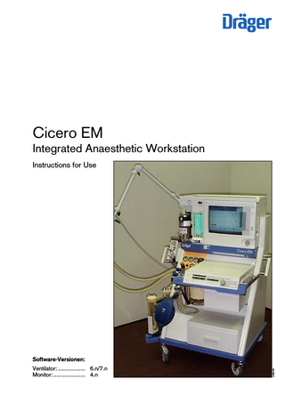
Cicero EM Integrated Anaesthetic Worthstation Instructions for Use
Instructions for Use
196 Pages
Preview
Page 1
Cicero EM Integrated Anaesthetic Workstation Instructions for Use
Ventilator: ... 6.n/7.n Monitor:... 4.n
23529278
Software-Versionen:
Working with these Instructions for Use
Each page is organized according to the following principles:
At the top – the subject ... of the main chapter as listed in the Overall Contents on page 3. It is always contained in a headline and printed in bold type at the beginning of the chapter.
Xxxxxxx Yxxxxxxxxx
Xxxxxxxxx ● Xxxxxxxxxxxxxxxxxxxxxxxxxxxx: Xxxxxxxxxx: Vxxxxxxxxx? Xxxxxxxxxxxxx: Hxxxxxxx ?, Fxxxxxxx ?, Dxxxxxx ? Xxxxxxxxx: Sxxxxxxxxxxxxx ?
1
Xxxxxxxxxx Xxxxxxx xxxxxxxxxxxxxxx 1 Xxxxxxxxxxx Xxxxxxxxxx xxxxx ● Xxxxxxxxxxxxx XXXXXXXXXX cccxxxxxxxxxxxxx xxxxx x 2 Xxxxxxxxxxxxxxxxxx xxxxxxxxx (X xxxxxxxxx).
2
Xxxxxxxxxxxxxxxxxxx Checkliste Cicero EM
● Xxxxxxxxxxxxxxx xxx Xxxxxxxxxxx xxxxxxxxx xxxxxxxx ● Xxxxxxxxxx - xxxxxx xxxxxxxxxxxx ! - xxx xxx Xxxxxxxxxx xxxxxxxxxxxx xxxxx ! ● Xxxxxxxxxx xxxxxxxx xxxxxx xxx xxxxxxxxx Xxxxxxxxxx xxxxxx xxx xxx Xxxxxxxxxxxxx:
Vor jeder Benutzung vom Anwender zu prüfen Vapor
Sicherheitsfüllvorrichtung Stecksystem
Narkosegasfortleitung Atemsystem Atemkalk Notbeatmungsbeutel
– xxxx. –
Zentralversorgung (ZV) Reservegasflaschen Sekretabsaugung
(xxxxxxxx X xxxxxxxx Xxxxxxxxxxx) ● Xxxxxx xxxxxxxxx xxxx xxxxxx Xxxxxxx xxxx Xxxxxxxxx. ● Xxxxxx xxx Xxxxxxx xxx Xxxxxxxx xxxxxxxxxx.
Gasversorgung ORC O2-Flush
06.12.98
11:59 00:00
Druck O2, Air, N2O > 2,7 bar Druck O2, Air > 50 bar Unterdruck vorhanden
Cicero nach Checkliste o.k ? Bitte bestätigen
Pleth
Xxxxxxxxx xxxxxxxxx ● Xxxxxxxxxxxx xxxxxxxx 3 Xxxx xx Xxxxx xxx xx Xxxxx xxxxxxxxxx xcxxxxxxxx - xxx xxx Xxxxxxxcxx -
3 xxxxxx Xxxxxx Xxxxxxxxxxxxxxx xxxxx xxxxxxxxxxxxxx ! ● Xxxxxxxxxxxxx xx Xxxxxxxx xxxxx xxx xxxxxxxxxxxxx 4 Xxxxxxxx xxx xxx Xxxxxxxxxxx xcxx xxxxxxx xxxxxxxxx (xxxxxxxxxxxx) -
XYZ
Left-hand column – the text ... contains explanations, prompts the user to do something and describes the machine's response. The dots and numbers refer to actions, while the numbers also draw attention to details in the illustrations supplementing the text. The numbering starts anew on each page. Right-hand column - the illustrations ... make it easier to locate the various parts of the equipment. Details mentioned in the text are highlighted in bold type or coloured black.
Schauzeichen grün Fester Sitz und vollständig Kalk erneuert, kein Farbumschlag Funktion gewährleistet
Flow O2, Air, N2O vorhanden Funktion Umschalter Air/N2O gewährleistet Flow N2O sinkt proportional mit Flow O2 Strömungsgeräusch, Beutel füllt sich
O2-Xxxxxxx ● Xxxxxxxxxxxxx xxx Xxxxxx xxxxxx xxxxxcxxx ! Xxxxxxxx xxx xxx Xxxxxxxxxxxxxxx xxx Xxxxxxxx xxxxxxxx ● xxxxxxxxxxxxxxxx xxxxxxxxxxxxx xxxxxxxxxxxx
Nullstellung Füllung Zeit seit letzter Inspektion 6<Monate Verschlußschieber eingeschoben und festgezogen Adapter liegt gleichmäßig auf Verriegelt
4
TestAbbruch
Overall contents
For your safety and that of your patients
4
Intended use
5
Emergency Quick-Start
Notes Power failure Gas failure
6
Operating concepts
Master switch Ventilator operating concept Monitor operating concept
9
Preparing for use
Power supply Compressed gas supply Connecting external equipment Checking workstation with checklist
15
Anaesthesia ventilation
Spontaneous breathing/manual ventilation IPPV mode SIMV mode PCV mode Paediatric use Changing patients After use Basic screen configuring Monitoring functions in operation Alarm concept
31
System screen functions
45
Parameter Box
Function keys and indicators Measurement functions
85
Messages - Cause - Remedy
Location of valves and subsystems Warning, caution and advisory messages
99
Care
Stripping down machine Disinfection, cleaning and sterilization Disposing of throw-away articles Re-assembling machine
117
Checking readiness for operation
Checking machine functions Maintenance intervals
131
What's what
139
Technical data
151
Descriptions
Machine functions Operation of the ceiling version
163
Abbreviations and symbols
189
Index
191
3
For your safety and that of your patients
For your safety and that of your patients Strictly follow the Instructions for Use
Liability for proper function or damage
Any use of the apparatus requires full understanding and strict observation of these instructions. The apparatus is only to be used for purposes specified here.
The liability for the proper function of the apparatus is irrevocably transferred to the owner or operator to the extent that the apparatus is serviced or repaired by personnel not employed or authorized by DrägerService or if the apparatus is used in a manner not conforming to its intended use.
Maintenance The apparatus must be inspected and serviced regularly by trained service personnel at six monthly intervals (and a record kept). Repair and general overhaul of the apparatus may only be carried out by trained service personnel. We recommend that a service contract be obtained with DrägerService and that all repairs also be carried out by them. Only authentic Dräger spare parts may be used for maintenance. Observe chapter "Maintenance Intervals".
Accessories Do not use accessory parts other than those in the order list.
Not for use in areas of explosion hazard This apparatus is neither approved nor certified for use in areas where combustible or explosive gas mixtures are likely to occur.
Safe connection with other electrical equipment Electrical connections to equipment which is not listed in these Instructions for Use should only be made following consultations with the respective manufacturers or an expert.
4
Dräger cannot be held responsible for damage caused by non-compliance with the recommendations given above. The warranty and liability provisions of the terms of sale and delivery of Dräger are likewise not modified by the recommendations given above. Dräger Medizintechnik GmbH
Intended use
Intended Use Integrated anaesthetic workstation »Cicero EM« with system monitor Universally applicable, integrated anaesthetic workstation for – Inhalation anaesthesia for adults, children and neonates. – Inhalation anaesthesia in semi-closed to virtually closed systems with »low flow« and »minimal flow« techniques (for minimum gas and anaesthetic consumption). – Automatic ventilation (IPPV). – Synchronized intermittent mandatory ventilation (SIMV). – Pressure-controlled breathing (PCV) in the PCV ventilator. – Manual ventilation (MAN). – Spontaneous breathing (SPONT). – Automatic anaesthetic agent recognition. The following information is displayed in colour on the system monitor: – Airway pressure and temperature – Inspiratory O2 concentration – Expiratory tidal volume – Patient compliance – CO2 and anaesthetic concentration at the Y-piece – Fresh gas balance together with the main haemodynamic parameters monitored with the parameter box: – ECG curve with heart rate and ST segment analysis. – The real-time curve of the invasive blood pressure (iBP) in two channels, with the systolic, diastolic and mean pressure values. – The values of the non-invasive blood pressure (NiBP) with the systolic, diastolic and mean pressure values. – The body temperature in two channels. – The functional O2 saturation (SpO2) with the pulse rate. – The plethysmogram.
Other accessories (optional)
Notes on operation Only non-flammable anaesthetic agents conforming to EN 740 may be used. Risk of fire! Since this apparatus is not approved for use with inflammable anaesthetics (ether, cyclopropane, etc.), it is not necessary to use antistatic (conductive) breathing hoses or face masks. Conductive breathing hoses and face masks may cause burns during high-frequency surgery and are therefore not recommended for this apparatus. Any additional electrical equipment which is latched onto the top of the workstation must also be connected to the base unit by means of an equipotential bonding conductor! Electromagnetic fields exceeding the limits specified in EN 60601-1-2 may interfere with the operation of the device and therefore put patients at risk. Mobile radio telephones must not be used within 10 metres of the workstation! Cicero EM must not be used with magnetic resonance tomography (MRT, NMR, NMI). The workstation should only be moved by the handles! Always operate the device under the supervision of qualified medical personnel in order to obtain prompt assistance in the event of malfunction.
Retrofitting in different devices The software described in these Instructions for Use, in combination with the »Cicero EM«, has passed a conformity evaluation procedure conforming to 93/42/EEC (medical appliances); the corresponding conversion kits therefore bear the mark of conformity.
C
C
The conversion kit can also be installed in the »Cicero EM color« even if the unit itself does not bear the symbol, because the conformity evaluation procedure has confirmed the suitability of the product for this type of device.
Vapor*) Anaesthetic vaporizer for enflurane, isoflurane, halothane and sevoflurane. Connection for two Vapor vaporisers*) Devapor*) Anaesthetic vaporizer for desflurane. Anaesthetic gas scavenging system*) Uninterruptible power supply*) Passive air conditioning*) Heated breathing hoses. pEEG*)
*) Refer to the separate Instructions for Use for this equipment.
5
Emergency Quick-Start
D
Emergency Quick-Start Press the master switch (1) –
The pressure gauges (2) are in the green zone.
–
All lamps on the ventilator light up.
2 Gas/Power ON / I Press
I
Press a function key on the ventilator Recommendation: Press and hold down longer than 1 second.
key for
00129278
MAN SPONT
TEST
IPPV
SIMV
PCV
Pmax PPCV
VT
fIPPV
TI:TE
TIP:TI Flow
PEEP
O
fIMV
The message »Test interrupted« is displayed.
00229278
–
M
1
O
For devices without PCV mode (software 6.n):
Deliver fresh gas O2
–
With the delivery valve buttons (3) under the measuring tubes
–
If necessary fill the system rapidly with the O2 flush (4).
–
The manual ventilation bag should fill.
Set the APL pressure limiting valve (5) to »MAN« Set maximum pressure –
4
AIR
5 6
3
Turn the valve head (6) until the disc is at the desired maximum pressure. MAN SPONT
TEST
IPPV
PCV
Pmax PPCV
VT
fIPPV
TI:TE
TIP:TI Flow
PEEP
fIMV
00329278
SIMV
Lecktest ?
6
Emergency Quick-Start
Notes on Quick Start The Quick Start procedure is permitted a maximum of 10 times in succession, and only if the previous (full) selftest was completed without error. Otherwise, the display on the ventilator and the system screen instruct the user to run through the complete selftest.
Self-test
Manual ventilation remains possible under all conditions! Quick Start can also be triggered by the »Cancel Test« softkey.
●
Quick Start can be triggered at any time, even during a self-test.
cancel test
06-12-98
16:47 00:00
00429278
●
Self-test cancelled
If there is a power failure (manual ventilation is possible) Make sure that the master switch is pressed down –
The acoustic power failure warning is muted after 30 seconds.
Deliver fresh gas - set APL valve –
If required, press the O2 flush button (»O2 +«).
Note: If there is a power failure, the piston of the ventilator is pushed to its end position by the airway pressure. This increases the system volume by a maximum of 1.4 litres.
If there is a gas failure In case of AIR failure (medical air) –
The system automatically switches over to O2 supply.
In case of O2 failure –
The system automatically switches over to the AIR supply. An acoustic alarm is sounded (O2 shortage signal). The supply of N2O is disabled.
If both O2 and air fail The patient must immediately be ventilated with the separate emergency ventilation bag!
7
Operating concepts
Page Master switch... 10 Ventilator operating concept ... 10 Monitor operating concept ... 12
9
Operating concepts Ventilator operating concept
Ventilator operating concept Master switch for power and gas
D
1 Press to switch on. The switch clicks into position. 2 Turn clockwise to switch off.
Gas/Power ON / I Press
2
Hardkeys – for setting the operating modes I
»IPPV« key for IPPV mode.
1
O
00529278
»MAN / SPONT« key for manual ventilation or spontaneous breathing.
D
»SIMV« key for SIMV mode (see illustrations for the specific ventilator versions)
A
00629278
»PCV« key for PCV mode (for PCV ventilator). »TEST« key for leakage test and compliance measurement. Standby key.
for setting ventilation parameters
Ventilator with PCV MAN SPONT
TEST
IPPV
The same key is used in PCV mode to set the plateau pressure. »VT« key for setting the tidal volume. »IPPV« key for setting the ventilation frequency in IPPV mode. »TI : TE« key for setting the time ratio between inspiration and expiration. »TIP : TI / Flow« key for setting the relative inspiratory pause for IPPV and SIMV ventilation. The same key is used in PCV mode to set the inspiratory flow. »PEEP« key for setting the PEEP pressure for IPPV mode. »fIMV« key for setting the ventilation frequency in SIMV mode. 10
PCV
Pmax PPCV
VT
fIPPV
TI:TE
TIP:TI Flow
PEEP
fIMV
O 00729278
»Pmax / PPCV« key for setting the maximum pressure for IPPV and SIMV ventilation.
SIMV
Ventilator without PCV MAN SPONT
TEST
IPPV
SIMV
Pmax
VT
fIPPV
TI:TE TIP:TI PEEP
fIMV
O 00729278
Below the display window:
Operating concepts Operating concept of ventilator
Display window with dialogue function (in combination with the rotary control) Example: adjusting the maximum pressure In the black field, beside the rotary control:
2 The value on the right-hand side is changed by turning the rotary control. Here: »28«. The old and new values are consequently always displayed together.
23
00829278
1
Pmax / mbar
28
2
3 The value on the right (»28«) is confirmed as the definitive value by pressing the control.
3
00929278
1 The set value appears on the right and left-hand sides of the field when a parameter key (Pmax, VT, fIPPV) is pressed. Here: »23«.
If the rotary control is not pressed and not turned again, the machine is reset after 10 seconds without changing the setting. MAN SPONT
TEST
IPPV
SIMV
Pmax PPCV
VT
fIPPV
TI:TE
TIP:TI Flow
PEEP
O
fIMV
This dialogue window also displays advisory messages (see page 100) –
01029278
●
PCV
Kinderschlaeuche
Infant hoses
Example »Infant hoses«:
Display window without dialogue function Top left:
01129278
Continuous indication of the relative piston movement (in % referred to the set stroke volume VT). The set operating parameters correspond with the keys below: – Indication of the maximum pressure Pmax in mbar. – Indication of the tidal volume VT in mL or L. 0%
100%
23
600
12
mbar
ml/L
1/min
Pmax PPCV
VT
fIPPV
01229278
– Indication of the ventilation frequency fIPPV in breaths per minute.
11
Operating concepts Monitor operating concept
Monitor operating concept Hardkeys The right-hand side is reserved for operating elements, the left-hand side for displays.
E
This key switches the system screen from standby to measuring mode and vice versa. The system screen mode depends on the ventilator mode: Standby can only be selected on the system screen if the ventilator is also in standby.
This key is used to deactivate the alarm tone for two minutes. It is reactivated by pressing the key again. The yellow LED in the key lights up while alarms are suppressed (see page 79).
01329278
G
The system screen starts up when the ventilator is started.
During this period, any new advisory and caution messages will not be audibly signalled but will appear as text in the alarm fields. Only new warnings will be signalled once by the appropriate tone sequence. Inside the dark area, there are four keys acting directly on the screen contents:
S Q s U
This key is used to call up a menu of the available display options on the system screen. Selection is made by turning and pressing the rotary control (see page 68). This key always calls up the last standard screen used (see page 68). This key is used to »freeze« the curves on the display so that they can be viewed in more detail. This key is used to generate a manual entry in the list screen (see page 70).
G
01429278
Indicators
Above the key are two bar-shaped indicators that indicate the alarm status even when the acoustic alarm has been switched off. Red (upper) flashing lamp Yellow (lower) flashing lamp Yellow lamp constantly lit
12
Warning Caution Advisory
!!! !! !
Operating concepts Monitor operating concept
Softkeys 2 1
1 Beside the screen, on the right-hand side, there is an unmarked touch-sensitive keypad. 2 The function of these keys depends on the software and is indicated on the screen itself. Only those keys which can be activated are actually shown.
S
3
Pressing some of the softkeys or the screen selector key will open a menu. The area where selections can now be made is turquoise, and the cursor is a yellow rectangle. To select:
Turn rotary control.
01529278
●
The cursor moves within the turquoise area. ●
To confirm: Press rotary control. The selected function appears. Standby / Configuration
alarms inactive ! Settings
iBP 1
All menu levels are displayed in staggered arrangement. Inactivated menus are grey. The selected menu item is highlighted in black and white.
iBP 2
function
OFF
location
ART
sensitivity
42.5
50 ON
function
OFF
location
CVP
sensitivity
42.5
ON
50
ECG
mode adult neon.
NiBP
alarm limits
iBP locations
parameter
iBP channels
screen
SpO2 / Pleth
acoustic
CO2 / O2
list entry
pEEG transport RS 232 (Medibus) record (printer)
11:59 00:00
01629278
basic config.
Select a menu position. Please confirm ! Change the settings. Please confirm again !
IPPV alarm limits Anesth. Agent
Alarms
Calibration
3 Press the »Config« softkey.
mode
4 Under »Settings«, select the option »Colours«. ●
●
Settings
ART AORTA A.Pulm ZVD ICP iBP ? NiBP EKG SpO2/Pleth Temp. pEEG CO2 Flow Paw
Select the desired parameter in the colour menu and confirm. Turn the rotary control until the desired colour is displayed and then confirm
06-12-98
11:59 00:00
adult
neon.
alarm sound
1 2 3 4 5 6 7 8 9
pulse tone
0 1 2 3 4 5 6 7 8 9
pulse tone source
ECG
Pleth.
4
colours curve speed mm/s
12,5
25
50
call standard
Hintergrund
hell
dunkel
Module farbig
ja
nein
Wählen Sie mit dem Drehknopf einen Parameter aus. Bestätigen ! Wählen Sie die gewünschte Farbe. Bestätigen !
01729278
Configuring the colours
13
Preparing for use
Page Electrical power supply... 16 Equipotential bonding... 16 Uninterruptible Power Supply... 17 Compressed gas supply ... 17 Anaesthetic gas scavenging system ... 18 Anaesthetic vaporizer ... 19 Connecting external equipment ... 19 Parameter box ... 20 Checking workstation with checklist... 21 Manual tests... 21 Check Vapor... 22 Check anaesthetic gas scavenging... 22 Check breathing system ... 23 Check soda lime ... 23 Check emergency ventilation bag ... 23 Check piped medical gas supply ... 24 Check reserve cylinders (optional)... 24 Checking the secretion aspiration system ... 24 Check gas delivery... 25 Check Oxygen Ratio Control (ORC)... 25 Check O2 flush ... 25 End of manual test according to checklist ... 25 Self-test... 26 Semi-automatic part of the self-test... 26 Automatic self test ... 27 Fresh gas outlet (option)... 29
15
Preparing for use Electrical power supply Equipotential bonding
Preparing for use The device must be correctly prepared and checked before every use!
Connecting the electrical power supply The mains voltage must be within the voltage range specified on the nameplate on the back panel. 1 Plug the power plug into the wall socket. Auxiliary mains sockets: 2 Sockets for additional devices that are switched on and off with the master switch. (3 sockets. Maximum current per socket: 2 A) The sum of the derived current in the mains line must not exceed 500 µA (IEC 601/1).
P
3
2
01829278
1
Equipotential bonding (e.g. for intracardial or intracranial operations) 3 Connect one end of the earthing cable to the terminal stud on the back panel. ●
16
Connect the other end to the equipotential bonding stud, e.g. on the operating table or ceiling lamps.
Preparing for use UPS Compressed gas supply
Uninterruptible Power Supply (optional, see Instructions for Use of the UPS) When the machine is powered by the UPS battery during a mains power failure, no power is supplied to the auxiliary sockets! The Desflurane Vapor unit is powered by the side connector for non-heating apparatus (No. 9 on page 140) and will therefore continue to run as normal. 1 Plug the Cicero power plug into the socket of the UPS. 2 Plug the UPS mains plug into the mains socket. The UPS can supply the Cicero EM with electrical energy for about 45 minutes. It is activated automatically in the event of a power failure.
1 S3
S4
F2
F2
g
F3
F4
S5
I 0
S6
2
USV - Ein / On manuell
01929278
In the case of a ceiling unit, the auxiliary sockets are not fitted.
Connecting the compressed gas supply 3 Screw hoses for O2, AIR and N2O into the rear of the apparatus and plug connectors into the wall sockets. Switch-on lock: If the machine is switched on without pressure on the O2 line, it is impossible to meter the other gases for safety reasons!
3 4
»Pressure supply« appears on the ventilator. ●
Connect O2 supply and confirm.
●
Check that the supply pressure is adequate on the pressure gauges on the front (pointers must be in the green area).
4 Holder for anaesthetic gas scavenging. See next page and separate Instructions for Use. If the machine is equipped with a vacuum bronchial aspirator (option), a vacuum supply system must be connected. 02029278
●
17
Preparing for use AGS-system Bronchial aspirator
Installing the anaesthetic gas scavenging system: ●
D
Hook the collecting system to the mount on the back of the Cicero: Place the slots of the receiving system over the holders and slide the receiving system down. See also "What's what" on page 146, No. 14.
Detailed view from below after removing soda lime container.
Connecting the transfer hoses 1 Pass transfer hose from behind through the hole in the Cicero EM and
2
1 02129278
2 connect the hose to the scavenging connector of the breathing system (only on first installation - the hose then remains on the connector). 3 Connect the transfer hose to the connector on the receiving system. ●
4
Make sure the connection is secure!
4 Make sure that the connector for the second transfer hose is sealed with a screw plug. Do not plug the openings of the receiving system, otherwise the breathing system could be drained.
3
5
1 02229278
5 Connect the scavenging hose to the output connector of the scavenging system.
6 02329278
6 Plug the connector of the scavenging hose into the wall socket. The visual indicator shows »green«.
D
18
Preparing for use Anaesthetic vaporizer External equipment
Anaesthetic vaporizer: –
Only use the Vapors listed in the list of accessories!
–
Note the separate Instructions for Use of the Vapor.
–
3 2 0 Vol.
Only use the Vapor intended for each anaesthetic agent!
%
1 The fill plug must always be inserted and securely tightened! 2 The thumbwheel must always be set to zero when there is no fresh gas flow.
02429278
3 Vapor must always be secured by means of the locking lever (set to the left-hand limit).
1 Connecting external equipment Connection via the printer interface: 4 with a data cable for printers with serial interface, such as: Deskjet (made by Hewlett-Packard)
4 Connection via the Dräger RS 232 MEDIBUS interface: 5 with data cable for standard PCs or other monitors. ●
6
Paw
CAN
P-Box
VGA extern
m
7 8 VGA intern
O2
Temp. * / Spiro
P 02529278
5
For interface configuration, see page 64.
RS 232 C
Equipment plugs must be secured with screws!
Vent.
●
RS 232 C
This connector may also be used as an RS 232 MEDIBUS interface.
Equipment plugs must be secured with screws!
For interface configuration, see page 63.
After removing the outer back panel, the following connections are accessible: External screen 6 Any S-VGA-compatible screen can be connected. External O2 sensor for inspiratory measurement: 7 Connect to the socket marked »O2«. Airway temperature sensor 8 Connect to the socket marked »Temp«.
19
Preparing for use Parameter box
Fitting the parameter box The parameter box can be operated either in the blue holder or in the slot-in housing. The slot-in housing can be mounted by Dräger Service on the left-hand side of the Cicero EM. The blue holder can be mounted by the user in any position on a standard rail (10 x 25 mm).
EM ero Cic
D
1
In the blue holder, the parameter box can be tilted up and down. In the slot-in housing its position is rigidly fixed.
02629278
In both cases, the synchronising output for an external defibrillator is accessible from the rear.
Slot-in housing: 1 Push the parameter box straight into the slot-in housing. The parameter box locks into position, and the electrical connections are made.
3 2 02729278
To remove the parameter box, pull the blue handle on the box to release the locking lever. The parameter box can then be simply pulled out of the housing. Blue holder: 2 Fix the blue holder in a suitable position. 3 Connect the cable of the mounting base to the connector on the side of the Cicero EM.
6
4 Hang the parameter box onto the mount from above. The plug connector must engage.
6 Defibrillator connection.
02529094
5 To remove, pull the blue handle on the parameter box. The parameter box is released and can be taken out of the blue holder.
5
4
02629094
Tilting the parameter box: 7 The parameter box can be swivelled up and down.
7
02729094
The parameter box is the central component of the Dräger transport function. See the separate section in these Instructions for Use, page 86.
20
Preparing for use Checking workstation with checklist
D
Checking workstation with checklist Manual tests: After switching on, the apparatus runs through a self-test. Prerequisites:
Gas/Power
Machine is fully equipped Instructions for Use are familiar User has been instructed on using the machine -
ON / I Press
I
Switching on:
O
00129278
1
Duration: approx. 5 minutes
1 Press the master switch. (Combined master switch for gas and power) The self-test starts The user must first check: On the ventilator: Self-Test
– Indication of software version, all indicator lamps light up for approx. 2 seconds. A single tone sounds.
»Self-test« appears briefly in the display window. The Ventilator display goes dark. No operations on the ventilator are required during the self test. On the screen:
02929278
D
– The message
Technology for Life
– The internal program memories are tested. All LEDs and display elements light up for approx. 2 seconds. The LED in the standby key remains lit.
E
Cicero EM Version 4.0 06-12-98
– Two warning tones sound.
Self-test In case of emergency: press any ventilator function key for quick startup
03029278
– A clock symbol u appears on the screen = duration of self-test. – The keys are still inactive. Please wait!
Check-list Cicero EM
Shortly afterwards:
To be verified by the user prior to each use Vapor
– The checklist appears.
Safety-fill
Indication in user advisory field: Is the Cicero EM o.k. according to checklist? Please confirm!
●
Gas scavenger Breathing system Soda lime Emergency breathing bag
The user is consequently prompted to check the points listed.
Central gas supply Backup cylinders Suction
The equipment must be checked every time, immediately before being used!
Gas delivery ORC O2-flush
06-12-98
11:59 00:00
operational complete, locked in place no colour change present, functional
all pressures greater than 2.7 bar all pressures greater than 50 bar functional
cancel test
O2, Air, N2O present N2O flow changes proportionally to O2 audible flow, breathing bag fills
03129278
●
handwheel set to zero fill - level ok less than 6 months since last inspection correctly seated and locked plug secured in place
Is the Cicero EM o.k. according to check-list ? Please confirm !
21
Preparing for use Checking workstation with checklist
Check Vapor:
Check-list Cicero EM To be verified by the user prior to each use
– Set the handwheel to »O «.
Vapor
handwheel set to zero fill - level ok less than 6 months since last inspection correctly seated and locked plug secured in place
– Filling level OK? Safety-fill
03129278
– Last inspection less than six months ago? Safety filler: – The plug is inserted and secured. Vaporiser mount:
0
– Vaporiser is correctly seated.
Vol.
%
Locking mechanism:
02429278
– Plug-in system is locked (lever to the left as far as possible).
Gas scavenger Breathing system Soda lime Emergency breathing bag
C
t l
l
Check anaesthetic gas scavenging:
ll
p ug secu ed n p ace
operational complete, locked in place no colour change present, functional
t
th
27b
03129278
Safety f
D
– Is indicator in wall socket green? (Only when using Dräger systems; note sounds of gas flow in other cases.) – Hose connected to breathing system?
– Are the two hoses fitted correctly?
1 02229278
– Is the anaesthetic gas scavenging system correctly installed?
– Are the vents open? – Are all hoses free of kinks?
03229278
1 Is the transfer hose of the anaesthetic gas scavenging system free of condensate? Drain if necessary.
22