Dräger Medical
Babylog 8000 series Technical Documentation IPM Rev 1.0
Technical Documentation
332 Pages
Preview
Page 1
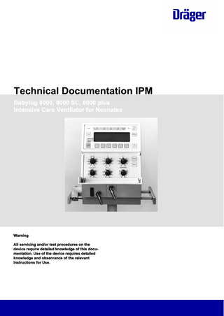
Technical Documentation IPM Babylog 8000, 8000 SC, 8000 plus Intensive Care Ventilator for Neonates
Warning All servicing and/or test procedures on the device require detailed knowledge of this documentation. Use of the device requires detailed knowledge and observance of the relevant Instructions for Use.
No.0811-0000001917_Publication
– This page has been intentionally left blank –
2
Babylog 8000, 8000 SC, 8000 plus
Table of contents
Table of contents 5 6 9 10 45 46 47 49
No.0811_0000001917_Publication
General General notes... Function descriptions Function description... Maintenance instructions Cooling Air Filter... O2 Sensor... Annex
Babylog 8000, 8000 SC, 8000 plus
3
No.0811-0000001917_Publication
– This page has been intentionally left blank –
4
Babylog 8000, 8000 SC, 8000 plus
General
This chapter contains general notes and definitions that are important for the use of this documentation. 6
Babylog 8000, 8000 SC, 8000 plus
5
No.0811_0000001917_Publication
General notes ...
General General notes
General notes
Notes on use
Read through the following notes thoroughly before applying this documentation. Dräger reserves the right to make changes to the device and/or to this documentation without prior notice. This documentation is intended solely as an information resource for experts.
Copyright and other protected rights
The content of this documentation, in particular its design, text, software, technical drawings, configurations, graphics, images, data and their selection and its composition and any amendments to it ("content") are protected by copyright. The content must not (in whole or in part) be modified, copied, distributed, reproduced, republished, displayed, transmitted or sold without the prior written consent of Dräger.
Definitions WARNING! A WARNING statement provides important information about a potentially hazardous situation which, if not avoided, could result in death or serious injury. CAUTION A CAUTION statement provides important information about a potentially hazardous situation which, if not avoided, may result in minor or moderate injury to the user or patient or in damage to the medical device or other property. NOTE A NOTE provides additional information intended to avoid inconvenience during operation and/or servicing. =
Identification of actual condition
Maintenance
=
Measures to maintain the specified condition
Repair
=
Measures to restore specified condition
Servicing
=
Inspection, maintenance, repair
No.0811_0000001917_Publication
Inspection
6
Babylog 8000, 8000 SC, 8000 plus
General General notes
General safety precautions
Read through each section thoroughly before beginning servicing. Always use the correct tools and the specified test equipment. Otherwise the device may not work correctly or may be damaged. WARNING! Improper servicing If the medical product is not properly serviced, the safety of the patient and/or the operator may be put at risk. –
Have the medical product checked and maintained on a regular basis by appropriately qualified experts, otherwise the proper functioning of the device may be compromised.
–
Have repairs to the medical product carried out only by personnel who have undergone product-specific Dräger training.
NOTE Dräger recommends entering into a service contract with DrägerService and having all repairs likewise carried out by DrägerService. WARNING! Replacement parts not certified by Dräger standards Dräger cannot guarantee or confirm the operational safety of third-party replacement parts used on the device. –
Use only replacement parts certified to Dräger standards for servicing of the device, otherwise the proper functioning of the device may be compromised.
–
Pay attention to the „Servicing“ section of the Instructions for Use.
WARNING! Non-conforming test values If test values do not conform to specifications, the safety of the patient may be put at risk. –
Do not put the device into operation if test values do not conform to specifications.
–
Contact your local service organization.
WARNING! Impermissible modifications to the device If impermissible modifications are made to the device, the safety of the patient may be put at risk. –
Do not modify the device without Dräger's permission.
No.0811_0000001917_Publication
WARNING! Risk of infection The device may transmit pathogens following use on the patient. –
Before carrying out any servicing, ensure that the device and its components have been handed over by the user cleaned and disinfected.
–
Service only cleaned and disinfected devices and device components.
Babylog 8000, 8000 SC, 8000 plus
7
General General notes
WARNING! Risk to patients –
Ensure that no patient is connected to the device before starting maintenance or repair work.
NOTE
No.0811_0000001917_Publication
Where reference is made to legislation, regulations and standards, in respect of devices used and serviced in Germany they are based on the laws of Germany. Users and technicians in other countries must comply with their national laws and/or international standards.
8
Babylog 8000, 8000 SC, 8000 plus
Function descriptions
This chapter contains descriptions of the device's technical functions. 10
No.0811_0000001917_Publication
Function description...
Babylog 8000, 8000 SC, 8000 plus
9
Function descriptions Function description
Function description
General
Ventilation modes
Additional Functions
Babylog 8000/Babylog 8000 plus has a flow measurement function. The Babylog 8000 SC has no flow measurement, but can be upgraded to a Babylog 8000 using the “flow measurement” conversion kit. The Babylog 8000/Babylog 8000 plus/Babylog 8000 SC offers the following ventilation modes: –
IPPV (Intermittent Positive Pressure Ventilation), controlled and assisted constant-volume ventilation
–
SIPPV (Synchronized Intermittent Positive Pressure Ventilation), synchronized controlled and assisted constant-volume ventilation
–
IMV (Intermittent Mandatory Ventilation)
–
SIMV (Synchronized Intermittent Mandatory Ventilation) weaning method for spontaneously breathing patients
–
CPAP (Continuous Positive Airway Pressure) spontaneous breathing with positive airway pressure
–
PSV (Pressure Support Ventilation) (optional as of software version 5.n)
The Babylog 8000/Babylog 8000 plus/Babylog 8000 SC has the following (optional) additional functions: –
High-frequency ventilation (HV) (as of software version 4.n)Volume guarantee (VG) (as of software version 5.n)
–
Volume guarantee (VG) (as of software version 5.n)
CAUTION The PEEP/CPAP rotary knob has been modified in Babylog 8000/Babylog 8000 plus with software version 5.n or higher. The user must intentionally initiate a PEEP/CPAP setting below 2.5 mbar (2.5 cmH2O), an additional method of patient monitoring (e.g. respiration, SpO2) must be used so that a patient disconnection and/or its direct consequences are reliably detected and appropriately alarmed.
–
Setting of small PEEP/CPAP values is limited at 2.5 mbar by a mechanical lock. Values below 2.5 mbar can only be set after deliberately overcoming this mechanical lock.
The Babylog 8000/Babylog 8000 plus/Babylog 8000 SC contains the following integrated monitoring: –
Fraction of inspired O2 (FiO2)
–
Airway pressure (Paw)
–
Flow (Flow *) (Babylog 8000/Babylog 8000 plus)
–
Minute volume (MV)
–
Tidal volume (VT) No.0811_0000001917_Publication
Monitoring
–
10
Babylog 8000, 8000 SC, 8000 plus
Function descriptions Function description
Block Diagrams Block Diagram of the Components in Babylog 8000 / Babylog 8000 SC with LC Display
Assemblies of the Babylog 8000/Babylog 8000 SC with LC-Display
No.0811_0000001917_Publication
Fig. 1
Babylog 8000, 8000 SC, 8000 plus
11
Function descriptions Function description
Block Diagram of the Components in Babylog 8000 / Babylog 8000 plus with EL Display
Assemblies of the Babylog 8000/Babylog 8000 plus with EL Display
No.0811_0000001917_Publication
Fig. 2
12
Babylog 8000, 8000 SC, 8000 plus
Function descriptions Function description
Block diagram of the Babylog 8000 / Babylog 8000 SC / Babylog 8000 plus
Fig. 3
Airway monitoring
Assemblies of the Babylog 8000/Babylog 8000 SC/Babylog 8000 plus
In the ventilation modes IPPV/IMV and CPAP, the airway pressure (Paw), the flow at the Y-piece VT (Babylog 8000), and the fraction of inspired O2 (FiO2) are measured. Depending on the selected mode and the menu settings, the parameters are monitored and displayed on the screen. Pressure and flow curves as well as their storage can be displayed graphically on the LC display or EL display. In all ventilation modes, the chronological sequence of the airway pressure (Paw) is displayed in the LED bargraph.
No.0811_0000001917_Publication
Airway pressure
Two internal pressure sensors measure the pressure at the inspiratory outlet (Pinsp) and the pressure at the expiratory inlet (Pexp). The airway pressure is calculated as follows: Paw = Pinsp – 0.7 (Pinsp – Pexp) The following pressures are calculated from the Paw pressure signal: –
Peak pressure (Peak)
–
Mean airway pressure (Pmean)
–
Positive end-expiratory pressure (PEEP)
Babylog 8000, 8000 SC, 8000 plus
13
Function descriptions Function description
The peak pressure is the maximum positive pressure of the most recent respiratory cycle. After 30 s, at the latest, a new respiratory cycle must be recognized and a new measured value for the peak pressure must be generated, otherwise the current measured value is no longer valid and is removed from the display. The mean airway pressure is the initial value of a software digital filter. The PEEP is either the pressure value during the expiratory phase at a zero expiratory flow or the last measured value before the next inspiration. Like the peak pressure, the PEEP is no longer valid after 30 s and is removed from the display if a new measured value is not generated within the 30-s period. Trigger Signal
In order to generate a trigger signal, the inspiratory flow must be integrated during spontaneous breathing and compared to the adjustable trigger threshold.
Measurement of the inspired O2
A O2 sensor in the inspiration line measures the O2 content of the respiratory gas. Calibration data of the O2 sensor is maintained after switching off the Babylog. If the Babylog has been out of operation for more than 24 hours, a calibration will automatically be carried out upon power-on. The operator may also initiate a calibration manually, e.g. as required after replacing an O2 sensor. A two-step calibration with 21% and 100% O2 is always carried out in order to achieve a higher measurement accuracy over the whole concentration range and/or to be able to recognize a spent sensor cell. The calibration procedure is described under section “ Monitoring functions”. If the O2 measurement fails, the Babylog generates an alarm. This alarm status is shown in the status field of the screen by the flashing indication "FiO2"
Patient flow (Babylog 8000/ Babylog 8000 plus)
A direction-sensitive hot-wire flowmeter integrated into the Y-piece measures the inspiratory and expiratory flows through the tube. This measurement function must be reactivated each time after switching on Babylog and after each replacement of the sensor by calibrating the sensor. The flow signal is used to calculate the following values: –
Tidal volume (VT)
–
Minute volume (MV)
–
Percentage of the MV uptake through spontaneous breathing
–
Tube leakage
Unlike the tidal volume, the minute volume is not related to a respiratory cycle. In the same way the inspiratory MV is calculated for leak rate detection. The expiratory minute volume is displayed. In addition to the complete minute volume, Babylog also calculates the expiratory minute volume uptake through spontaneous breathing. Babylog calculates the percentage by comparing the total minute volume and the minute volume uptake through spontaneous breathing:
14
Babylog 8000, 8000 SC, 8000 plus
No.0811_0000001917_Publication
The tidal volume is the expiratory flow signal applied between two breathing phase cycles.
Function descriptions Function description
spont. = (MVspontan/MV) * 100% The leakage at the tube can be estimated by comparing the inspiratory and the expiratory minute volume. The leakage at the tube L is calculated as follows: L= (MVinsp _ MVexp)/(MVinsp + MVexp) * 100 The respiratory rate f is measured through the inspiratory respiratory phase cycles. All measured values derived from the patient flow become valid only after successful calibration of the flow sensor. If the flow sensor or the measuring electronics fails, an alarm is generated. However, Babylog can still be used without the functions depending on the flow measurement. This alarm status is shown in the status field of the screen by the flashing indication "flow".
Monitoring functions Fraction of inspired O2 (FiO2)
The system checks whether limit values are kept and all functions are ok. If a function fails or if the limit values are not met, Babylog will generate an alarm. O2 Measurement The measured O2 value is checked against upper and lower limit values. The alarm limits are automatically set at ±4 vol.% below the set FiO2value. A time delay makes sure no alarm is activated when the set value (O2) is changed or when the O2 sensor is calibrated. The absolute sensor voltages are checked. The differential voltage between the two sensor cells must be lower than (U1 + U2)/8 +1 mV. The output voltage of each individual cell must be between 9.5 mV and 123.6 mV. O2 Calibration The O2 sensor is either automatically calibrated 24 hours after the last calibration or manually after selection from the mode menu. If the O2 sensor is replaced during operation the new O2 sensor will be calibrated automatically. Babylog does not detect a replaced sensor if the replacement took place while the device was off. In this particular case, the operator has to calibrate the new O2 sensor manually.
No.0811_0000001917_Publication
By switching over a valve the sensor is separated from the respiratory gas flow and purged with the calibration gas (O2). This leads to a change in concentration at the O2 sensor. The switching of the calibration valve is detected by this change of concentration. The calibration valve is deactivated as soon as the calibration is completed. A two-step calibration with 21% O2 and 100% O2 is carried out in order to achieve a higher measurement accuracy over the whole concentration range and to be able to recognize a spent sensor cell.
Babylog 8000, 8000 SC, 8000 plus
15
Function descriptions Function description
During the calibration procedure the microprocessor system processes (synchronizes) one of the two O2 sensor channels. The O2 channels are then submitted to a specific sequence of states controlled by one of the microprocessor systems and monitored for correct sequence and maximum period by the other. For instance, searching of the calibration values for 21% or 100% must not last longer than 3.5 minutes each. The calibration value for 21% must be between 9.2 mV and 26 mV, and for 100% between 43.6 mV and 123.6 mV; this applies to both channels. The zero voltage resulting from both values must be between –6 mV and +6 mV. After calibration is completed, the software checks whether the limit values respond correctly. Calibration stops if a control gas fails. Compressed-gas supply
The current measured values of the O2 and AIR gas supplies are considered when the valve bank is adjusted. The inlet pressure for O2 and AIR is 1.7 bar. If the pressure falls below the limit value, a visible and audible alarm is generated. The operator is informed about the cause of the alarm by a plain text message on the display. If the adjusted O2 concentration is 21% or 100%, only an advisory message (no alarm) is displayed if the non-added gas type fails. If the pressure exceeds the limit value, the safety venting mechanism is activated and the continuous flow is switched off. The Babylog will continue to operate only when the pressure has decreased to a permissible level.
Airway Pressure Monitoring
Depending on the selected mode and parameter settings, a certain airway pressure time profile is set. The Babylog generates an alarm if the actual profile is different.
Disconnect monitoring
The Babylog recognizes whether the hose system is connected incorrectly. If the hose system has been connected incorrectly, the continuous flow is (partly) directed to atmosphere. No pressure builds up in the hose system. Babylog checks during each breathing cycle whether a sufficiently high pressure is available during inspiration. Since inspiratory breaths occur in the mandatory ventilation modes IPPV/IMV, SIPPV and SIMV, this monitoring does not function in the CPAP mode.
Fig. 4
16
Disconnect monitoring Babylog 8000, 8000 SC, 8000 plus
No.0811_0000001917_Publication
If the AIR supply fails, the Babylog control switches to O2 supply. If the O2 supply fails, Babylog 8000/8000 SC switches to AIR supply.
Function descriptions Function description
During each mandatory breath, the level of the disconnection pressure (Pdis) must be exceeded without interruption for at least the disconnection time (Tdis), otherwise an alarm will be generated. Pdis is a function of the settings Pinsp and PEEP. If Pinsp is set considerably higher than the actually attained pressure, the Pdis alarm level likewise increases. Depending on the flow and the inspiration time settings, the level might not be attained any more. Babylog generates an alarm even if there is no leakage in the breathing system. Babylog 8000 (software version 5.n) / Babylog 8000 plus (software version 5.n): CAUTION – Due to their functional principle (ejector) the devices affected (software version 5.n) operate near their limit range when very low PEEP values (less than 2.5 mbar) are set. Therefore, when using the Babylog 8000 plus (software version 5.n) or the Babylog 8000 (software version 5.n) and PEEP settings below 2.5 mbar, an additional method of patient monitoring (e.g. respiration, SpO2) must be used so that a patient disconnection and/or its direct consequences are reliably detected and appropriately alarmed. –
Overpressure and low pressure alarms
Setting of small PEEP/CPAP values is limited at 2.5 mbar by a mechanical lock. Values below 2.5 mbar can only be set after deliberately overcoming this mechanical lock.
During the inspiratory and expiratory phases, the airway pressure (Paw) must not exceed the set pressure limit by more than 10 mbar. If the set pressure limit is exceeded by 10 mbar to 20 mbar, Babylog generates an alarm and, at the same time, reduces the inspiratory breath time. The remaining time is added to the CPAP phase. If the set pressure limit is exceeded by more than 20 mbar, an alarm is activated and the breathing system is vented. In the CPAP phase, the airway pressure must be ±4 mbar of the set PEEP/CPAP. Otherwise an alarm will be generated. If the limit is exceeded by more than 10 mbar, venting is carried out as during the inspiratory phase even if the pressure falls below the absolute level of -2 mbar. These overpressure and low pressure alarms apply to all ventilation modes.
No.0811_0000001917_Publication
Babylog 8000 up to Software Version 3.0
Fig. 5
Alarms
Babylog 8000, 8000 SC, 8000 plus
17
Function descriptions Function description
Dynamic stenosis limit The dynamic stenosis limit applies to Babylog 8000 units with software version 4.0 and Babylog 8000 SC units with software version 1.0.The limit value is (Pinsp + 5 mbar). If this limit value is exceeded, the microprocessor system reads in the actual measured value at 8.3-ms intervals (sampling frequency). The limit value (Pinsp + 5 mbar) is subtracted from each of the actual measured values and entered in a summer. As soon as the sum of 40 mbar (stenosis 1) is reached, Babylog switches over from inspiratory phase to expiratory phase. If a sum of 70 mbar is reached, despite of the safety measure (stenosis 1), the system will carry out an emergency venting.
Fig. 6 Minute volume monitoring (Babylog 8000/ Babylog 8000 plus)
Dynamic stenosis limit
The abbreviation MV (for minute volume) is used in the following text. Babylog 8000 with Software Versions 2 and 3 The monitoring menu is used to set the upper and lower alarm limits in the range of 0.03 L/min to 15 L/min. The upper and lower alarm limits are continuously compared with the measured MV value. If the value exceeds the upper alarm limits or falls below the lower alarm limit, the system will activate an alarm. Monitoring is deactivated during calibration of the flow sensor to allow the measured MV value to stabilize. If the flow measurement system fails, the MV monitoring becomes ineffective.
The monitoring menu is used to set the upper and lower alarm limits in the range of 0.00 L/min to 15 L/min. The upper and lower alarm limits are continuously compared with the measured MV value. If the value exceeds the upper alarm limits or falls below the lower alarm limit, the system will activate an alarm. Monitoring is deactivated during calibration of the flow sensor to allow the measured MV value to stabilize. If the flow measurement system fails, the MV monitoring becomes ineffective.
18
Babylog 8000, 8000 SC, 8000 plus
No.0811_0000001917_Publication
Babylog 8000 Software with Version 4.0 or Higher
Function descriptions Function description
Babylog 8000 plus The Babylog 8000 plus has software 5.n installed Audible Alarm Generator Monitoring
The Babylog has two signal tone generators (loudspeaker and piezo). During normal operation, the loudspeaker is the audio interface to the operator in the event of alarms. The piezo is only used in the event of power or loudspeaker failure. At the end of the self-test, the loudspeaker is triggered with a test signal. This test signal is monitored with a microphone. If there is no feedback, the Babylog generates error 817.
Operating voltage monitoring
During operation, the Babylog uses comparators to continuously monitor whether the operating voltages are within specified limits. When the Babylog is switched on, these comparators are checked by a defined changing of the comparator reference voltage.
Rotary potentiometer monitoring
Input via rotary potentiometers are processed by two channels. Two microprocessor systems read the input via independent channels and compare the results.
ROM Test
During operation, the ROM area used is summed up per byte in a long word variable (long word = 32 bits) which is compared to the check sum stored in the ROM. If the check sums do not match, an error message will be displayed.
RAM Test
During operation the RAM area used is tested with a simple algorithm. By writing 55 hex or AAhex in each cell every bit is checked for settability and resettability.
Temperature monitoring
A temperature sensor measures the internal temperature of the Babylog. If the temperature is not within the range of –20 °C to 75 °C, an alarm will be generated. If the temperature is too high, a message will inform the operator about a possible failure of the fan.
Relay and Valve Monitoring
An excess-current monitoring function is integrated into the trigger electronics of the valves. The excess-current monitoring is checked after the Babylog is switched on. If a valve is switched on and operated with the operate voltage for an excessive period of time, the excess-current monitoring function responds within a specific time. The relay which enables de-energizing of the whole pneumatics assembly is also tested once after power-on. For this purpose, the relay is switched on and off once and the voltages at the relay contact are measured. During operation, the system checks whether the voltage at the relay contact corresponds to the switching condition.
No.0811_0000001917_Publication
Battery monitoring
The Babylog contains a rechargeable NiCd battery for power failure alarm. The battery is recharged automatically during operation and its charge checked periodically. An error message is displayed if the voltage is too high or too low.
Flow measurement monitoring (Babylog 8000/ Babylog 8000 plus)
During operation, the flow sensor is checked for correct functioning, freedom of damage and intact contacts.
Babylog 8000, 8000 SC, 8000 plus
19
Function descriptions Function description
Alarms, cautions and advisory messages
The Babylog alarm structure has three priority levels:
Alarms
=
Immediate action required.
Warnings
=
Checking required.
Notes
=
Information for the operator.
The priority level is indicated by the different tone sequences of the individual audible alarm. Message display
When an alarm occurs the corresponding message is displayed as plain text message in a window of the display. The message can be canceled momentarily by pressing the Reset/Check key (or OK key as of software version 5.n). After a certain time out, the message appears again if its cause still exists. If several alarms have occurred simultaneously, the highest-level alarm is shown on the display. Other alarms will be queued. A message whose cause no longer exist will not be displayed any more.
Display and Menu
The display shows parameters and text messages. The functions of the Babylog are set with keys and potentiometers. The screen is separated into different areas:
Fig. 7
Screen display structure
–
The graphics field displays real-time curves.
–
The measured-value field displays monitoring parameter in digital representation.
–
The status field displays the operating mode and other status information.
–
The menu line displays the current function of the keys below the screen.
In some cases, the graphics and measured-value fields are combined to form one large field.
The “Monitoring/Mode” key and the six keys below the LC display are used for the menu. The “Monitoring/Mode” key toggles between the two main menus, the monitoring menu and the mode menu. This works from any menu status always reaching the basic status of the other main menu. The function of the keys depends on the respective menu status and is indicated in the menu line of the display by an abbreviation or a symbol.
20
Babylog 8000, 8000 SC, 8000 plus
No.0811_0000001917_Publication
Babylog 8000/Babylog 8000 SC with LC Display