Pocket Guide
24 Pages
Preview
Page 1
D-21865-2020
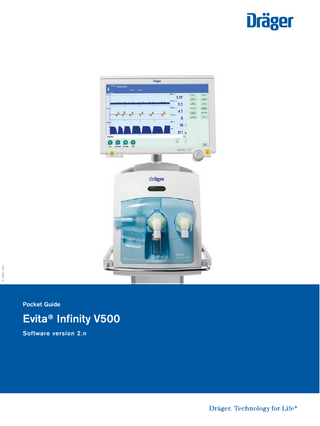
Pocket Guide
Evita® Infinity V500 Software version 2.n
02 |
QUICK GUIDE EVITA® INFINITY V500
Content System overview
04
Operating concept
08
Getting started
12
Operation
17
Alarms
20
Monitoring
22
The Evita® Infinity V500 Pocket Guide is not a replacement or substitute for the Instructions for Use. It is for informational purposes only. Any use of the device requires full understanding and strict observation of the Instruction for Use. The availability of functionality depends on the country and availability. Options may not be included in a present device or may come at extra costs. The pocket guide may not reflect the latest software version of the device.
| 03
Intended use Evita V500 ventilation unit The Evita V500 ventilation unit of the Infinity Acute Care System is intended for the ventilation of adults, paediatric patients and neonates. Evita V500 provides mandatory ventilation modes and ventilation modes for supporting spontaneous breathing and also airway monitoring. The Evita V500 ventilation unit is used with Dräger Infinity C Series Medical Cockpits. The Evita V500 ventilation unit is intended for use in different medical care areas. Infinity Medical Cockpit C700 Medical Cockpits are intended to be used to monitor waveforms, parameter information, and alarms as well as to control settings. The Infinity Series Medical Cockpits are intended to be used in environments where patient care is provided by trained healthcare professionals.
04 |
QUICK GUIDE EVITA® INFINITY V500
System overview Intensive care Ventilator
Display unit Infinity C500
Ventilation unit
Gas supply unit GS500 Power supply unit PS500 Trolley with 4 brakes
Evita® Infinity V500
| 05
System overview Cockpit Front Panel
Alarm bar
ON/OFF button AC power LED – lights up when the device is connected to AC power Battery LED – indicates battery status
Touch screen
Rotary knob (touch turn confirm)
Audio paused button
06 |
QUICK GUIDE EVITA® INFINITY V500
System overview Cockpit Back Panel
Alarm bar
VESA mounting holes
USB ports Isolated network connectors
Serial communication ports Single link Digital Visual Interface (DVI)
| 07
System overview Ventilation unit, front panel
Flap
Operation display of ventilation Expiration valve
Expiratory flow sensor Nebulizer port
Inspiration valve Emergency air intake
Water trap
08 |
QUICK GUIDE EVITA® INFINITY V500
Operating concept Main screen
Header bar Monitoring area with curves, loops, trends and measured values
Therapy bar with the therapy controls for the ventilation parameters of the active ventilation mode
Main menu bar with buttons for opening dialog windows and activating functions
| 09
Operating concept Main screen
Patient category
System data, e.g., state of charge of the batteries
Therapy status: Therapy type, ventilation mode, additional settings
Alarms, messages and instructions for the user
Alarm status: Alarm silence and display of remaining time
10 |
QUICK GUIDE EVITA® INFINITY V500
Operating concept Alarm priorities A certain priority, indicating the urgency, is assigned to each alarm. The following table shows the differences between the alarm priorities with respect to identification and the action required. Colour
Alarm priority
Action required
Red
High !!!
Immediate action is necessary in order to avert an acute danger
Yellow
Medium !!
Prompt action is necessary in order to avert a danger
Turquoise
Low !
Attention is necessary, but a delayed response is sufficient
Alarm message field: High priority alarm Alarm message field: Medium priority alarm Alarm message field: Low priority alarm
| 11
Operating concept Touch – Turn – Confirm Selecting and setting parameters and functions Touch the control element. The control element turns yellow.
Turn the rotary knob to the right or to the left to make the setting. The value is displayed in the control element.
Confirm by pressing the rotary knob. The setting is applied, and the control element turns grey or blue again.
12 |
QUICK GUIDE EVITA® INFINITY V500
Getting started Switching on Evita V500 and Infinity C500 Prerequisites:
– Evita V500, Infinity C500, PS500 and GS500 are reprocessed and assembled
– The mains power supply and the gas supply are connected.
Ventilation unit, left side: Toggle switch
– The Evita V500 toggle switch is set to On.
1. Press the key on Infinity C500. The system is started. The start dialog is displayed.
Evita V500 provides you with two options: – Use settings of previous patient or – Admit new patient
1.
– If the Start dialog is closed using the X button, Evita V500 adopts the settings of the previous patient.
| 13
Getting started Selecting the breathing circuit and the breathing gas humidifier
2. Touch the Br. circuit/ Humidifier tab.
2.
1. Touch the Start/ Standby ... button in the main menu bar.
3. Touch the button ▼.
3./4.
4. Select the breathing circuit used from the selection list. If the breathing circuit used is not included in the selection list select Other from the selection list. 5. Confirm with the rotary knob.
6.
1.
5.
5. Select the Humidification type.
Performing the device check
1. Touch the Start/ Standby ... button in the main menu bar.
2. Touch the System check tab.
3. Touch the Device check tab.
4. Touch the Start button.
2.
The system check is only possible in standby mode.
4.
3. 6.
5. Confirm with the rotary knob.
6. The questions must be answered by touching the Yes or No buttons. The Next test button can be used to skip the test steps. 5.
1.
14 |
QUICK GUIDE EVITA® INFINITY V500
Getting started Performing the breathing circuit check After the device check the user is requested to perform the check of the breathing circuit. Prerequisite: The System check page is opened. 1. Touch the Breathing circ. check tab.
2. Touch the Start button.
3. Confirm with the rotary knob.
2. 5./6.
4.
1.
4. When requested by Evita V500 in the instruction field: Seal the patient connection port, e. g., with a sterile glove. 3.
5. Confirm with OK.
6. When requested, open the patient connection port and confirm with OK.
Selecting a patient Admitting a new patient For a new patient, Evita V500 determines the ventilation parameters’ start up settings based on the patient category or the body weight Ventilation parameter startup settings by body height/body weight. Prerequisite: The Weight function was configured and a new patient was admitted.
1.
2. Set the body height by turning the rotary knob and push to confirm.
2.
1. Touch the button for the body height (In the Adult and Ped. pat. patient categories only).
| 15
Getting started Setting ventilation Ventilation parameter start-up settings by patient category The Start/Standby page contains the buttons for the patient category: – New Adult – New Ped. pat. – New Neo.
1.
1. Touch the button for the desired patient category.
2.
2. Confirm with the rotary knob.
In the Neo. patient category, the patient's body weight is set directly. The Start/Standby page contains the button for this start up body weight. 1. Touch the button for the start up body weight.
2. Using the rotary knob, set the start up body weight and confirm the value.
1.
2.
The button for the current body weight is displayed. After the patient has been admitted, the current body weight corresponds to the start up body weight.
16 |
QUICK GUIDE EVITA® INFINITY V500
Getting started Selecting the Tube or NIV application mode Evita V500 can switch between non-invasive ventilation and tube ventilation. 2.
The application mode can only be selected in standby mode. 1. Touch the Start/ Standby ... button in the main menu bar.
3.
2. Touch the Tube/NIV tab.
3. Touch the Tube or NIV button.
4. Confirm with the rotary knob.
1.
4.
Observe the information on changing the application mode!
Evita V500 can choose between therapy types Ventilation and O2 therapy. The therapy type can only be changed in standby mode.
2.
Selecting the therapy type
1. Touch the Start/ Standby ... button in the main menu bar.
2. The Start/Standby page is displayed. 3. Touch the Ventilation or the O2 Therapy button.
3.
4. Confirm with the rotary knob.
4.
1.
| 17
Operation 3.
Setting ventilation Opening the Ventilation settings dialog window.
The Ventilation settings dialog window can be opened as follows:
1.
1. Touch the Ventilation settings ... button in the main menu bar. or 2. Touch the button in the therapy bar. or 3. Touch the displayed ventilation mode in the header bar.
2.
Selecting ventilation modes The Ventilation settings dialog window contains tabs for selecting the ventilation modes. 1. 4 tabs have ventilation modes permanently assigned to them.
2. The Other modes tab can be used to select another ventilation mode, which can be selected from the available ventilation modes.
1.
2.
18 |
QUICK GUIDE EVITA® INFINITY V500
Operation Setting ventilation parameters 1. Prerequisite: The General settings page is opened.
2. Touch the corresponding therapy control, e. g., RR. The colour turns yellow.
3. Set the value by turning the rotary knob and push to confirm.
4.
4. Information is displayed in the message field, e. g., when the setting limit of a parameter has been reached.
1.
3.
2.
Additional settings for ventilation The ventilation modes can be combined with additional settings to optimize ventilation.
1. Touch the Additional settings tab.
2. Touch the tab of the respective additional setting.
4. Touch the corresponding therapy control.
5. Set the value by turning the rotary knob and push to confirm.
2.
1.
3. 4.
5.
3. Use the buttons to activate or deactivate the additional setting.
| 19
Operation 3.
Switching on O2 Therapy
2.
1. O2 therapy can only be switched on in standby mode. Touch the Start/ Standby ... button in the main menu bar.
3.
Evita V500 opens the Start/Standby dialog window.
1.
2. Touch the Standby button and confirm with the rotary knob.
2.
Evita V500 is in standby mode.
3. Touch the O2 Therapy button. The message field displays the information to use specific masks for O2 therapy.
Connect the mask for the O2 therapy. Touch the Start ventilation button and confirm with the rotary knob.
O2 therapy is switched on. Evita V500 displays the main screen with the therapy bar for O2 therapy. The message O2 Therapy is displayed in the header bar.
Ending operation 1. Switch Evita V500 to standby mode: Touch the Start/ Standby ... button in the main menu bar.
2.
2. Touch the Standby button and confirm with the rotary knob.
3. Press the key on Infinity C500.
Evita V500 opens the Shut down device dialog. Touch the OK button and confirm with the rotary knob.
1.
2.
3.
Evita V500 ends operation.
29 |
QUICK GUIDE EVITA® INFINITY V500
Alarms Display of alarms Optical alarm signals Alarm bar Alarm message field
Blinking parameter field
Display of alarms – Acoustic alarm signals Evita V500 generates different alarm tone sequences to indicate alarms acoustically. The acoustic alarm signal can be suppressed for 2 minutes maximum.
1.
1. Press the audio silence key.