Dräger Medical
Infinity Monitoring System
Infinity Acute Care System Quick Reference Guide sw VG7.n Edition 1 Aug 2018
Quick Reference Guide
32 Pages
Preview
Page 1
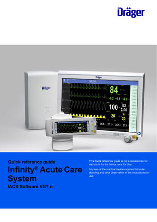
Quick reference guide
Infinity® Acute Care System IACS Software VG7.n
This Quick reference guide is not a replacement or substitute for the Instructions for Use. Any use of the medical device requires full understanding and strict observation of the Instructions for use.
Contents Contents... Trademarks... Side view of the M540... Dialogs and pages... To place the Cockpit in standby mode... To place the Cockpit into privacy mode... To admit a patient manually... To discharge a patient... To change the patient category in the Demographics page... To adjust the alarm volume... To initiate an audio pause from the Cockpit... To initiate an audio pause from the M540... To initiate an audio pause remotely... To pause alarm monitoring temporarily... To activate alarm monitoring after pausing... To deactivate alarm monitoring permanently... To activate alarm monitoring after deactivating. . . To configure the alarm settings... To configure the alarm settings of multiple parameters... To access the alarm history... To view a snapshot of a stored event... The Code function... Configuring the parameter content of the graphical trends... To modify the parameter selection for a graphical trend page... Electrode placement for adult and pediatric patients... ECG parameter setup functions... To select the arrhythmia modes... Accessing the arrhythmia functions... Respiration parameter setup functions... Patient preparation for respiration monitoring... SpO2 and Pulse CO-Ox monitoring with Masimo SET MCable... SpO2 and pulse rate monitoring with Nellcor OxiMax MCable... Temperature parameter setup functions... Non-invasive blood pressure parameter setup functions... Labeling Invasive pressure channels... Zeroing a pressure transducer... Invasive pressure parameter setup functions... To setup a PPV configuration... To calculate a PPV measurement... To setup an SPV configuration... To calculate an SPV measurement...
2
2 3 3 4 4 4 4 4
Mainstream CO2 monitoring... Microstream CO2 monitoring... Screen setup... Screen setup – auto view functions... Printing reports...
26 27 28 28 29
5 5 5 5 5 6 6 6 6 6 7 8 8 8 9 10 10 12 14 14 15 16 17 18 19 20 20 21 22 24 24 25 25
Quick reference guide
– Infinity Acute Care System – IACS VG7.n ®
Trademarks
–
Pulse CO-Oximeter Signal Extraction®
are trademarks of Masimo Corporation. –
Infinity®
–
MCable®
–
Medical Cockpit®
–
MPod®
–
are trademarks of Dräger. –
Microstream®
is a trademarks of Oridion Medical 1987 Ltd.
Masimo®
–
Nellcor®
–
OxiMax®
–
SatSeconds®
are trademarks of a Medtronic company.
–
SET® (Signal Extraction Technology)
–
Masimo® rainbow® SET®
All devices referenced in these instructions for use may not be approved for sale in all countries. Please check with your local Dräger representative.
Side view of the M540
A B F
C
310
D E A Non-invasive blood pressure connector
F
ECG connector
B Temp (2) / Aux connector C SpO2 connector D Hemo connector E CO2 connector
Quick reference guide
– Infinity Acute Care System – IACS VG7.n ®
3
Dialogs and pages The user can also access parameter-specific dialogs and pages directly by selecting the corresponding parameter fields on the main screen. For example, if the user selects the heart rate (HR) parameter field, the Sensor parameters dialog with the ECG page appears.
To place the Cockpit in standby mode 1
Select the
2
Select the Standby button on the toolbar.
symbol next to the Start/Standby... button on the main menu bar to display the Standby toolbar.
or 1
Select the Start/Standby... button on the main menu bar to display the Standby dialog.
2
Select the Start tab if it is not already selected.
3
Select the Standby button next to the menu selection Monitor.
To place the Cockpit into privacy mode 1
Select the symbol
2
Select Privacy on the toolbar.
next to the Start/Standby... button on the main menu bar.
or 1
Select the Start/Standby... button on the main menu bar.
2
Select the Start tab if it is not already selected.
3
Select Privacy next to the menu selection Display.
To admit a patient manually Touch the left most field on the header bar of the Cockpit to access the Demographics page. or 1
Select Start/Standby... on the main menu bar.
2
Select the Demographics tab (if not already selected).
To discharge a patient 1
Select the left most field on the header bar of the Cockpit to access the Demographics page.
2
Select the Start tab (if not already selected).
3
Select the Discharge button.
1
Select Start/Standby... on the main menu bar.
2
Select the Start tab (if not already selected).
3
Select the Start button. A pop-up window with the message Caution discharge will delete patient data appears.
4
Select the Discharge button in the pop-up window.
or
4
Quick reference guide
– Infinity Acute Care System – IACS VG7.n ®
To change the patient category in the Demographics page Select the left most field on the header bar to access the Demographics page directly. or 1
Select Start/Standby... on the main menu bar.
2
Select the Demographics tab (if not already selected).
3
Select the desired patient category button (Adult, Pediatric, or Neonate), next to the selection Patient category.
4
Press the rotary knob to confirm the setting.
To adjust the alarm volume 1
Select the Alarms... button on the main menu bar.
2
Select the Settings tab.
3
Select the button Alarm volume [%] and select the desired volume (5%, 10 to 100% in increments of 10%).
To initiate an audio pause from the Cockpit Press the yellow hardware version.
or
key on the Cockpit. The appearance of the yellow key depends on the Cockpit
or Press the F1 keyboard key. Pressing the key that initiated the audio pause period again, cancels the audio pause state, and all alarm events are reported as usual.
To initiate an audio pause from the M540 Press the yellow key on the M540 in an IACS configuration. You can audio pause alarms on the M540 when it is docked or while it is on transport.
To initiate an audio pause remotely Refer to the instructions for use of any remote device within the same monitoring unit for instructions on how to initiate an audio pause. Pressing the key that initiated the audio pause period again, cancels the audio pause state, and all alarm events are reported as usual.
Quick reference guide
– Infinity Acute Care System – IACS VG7.n ®
5
To pause alarm monitoring temporarily 1
Select the
symbol next to the Alarms... button on the main menu bar of the Cockpit.
2
Select the All alarms paused button.
To activate alarm monitoring after pausing 1
Select the
symbol next to the Alarms... button on the main menu bar of the Cockpit.
2
Select the All alarms paused button again.
To deactivate alarm monitoring permanently 1
Select the
symbol next to the Alarms... button on the main menu bar of the Cockpit.
2
Select the All alarms off button on the toolbar.
To activate alarm monitoring after deactivating 1
Select the
symbol next to the Alarms... button on the main menu bar of the Cockpit.
2
Select the All alarms off button again on the toolbar.
To configure the alarm settings 1
Select Sensor parameters... on the main menu bar.
2
Select the desired parameter tab (for example, ECG).
–
Str/Rec – stores an event for later review and generates a timed recording.
or Select the parameter field to access the parameter setup page directly. 3
Select the Alarm on/off button (A), to activate or deactivate alarm monitoring. A crossed-out triangle appears in the parameter field when alarm monitoring is deactivated.
4
Select the setup button (C) to adjust the upper alarm limits.
5
Select the setup button (D) to adjust the lower alarm limits.
6
Select one of the following settings for the Archive buttons (E) to determine what happens in response to an alarm:
6
–
Off – no event is stored and no recording is generated.
–
Store – stores the event for later review.
–
Record – generates a timed recording.
A C
A C
A C
D E
D E
D E
Quick reference guide
B
F
– Infinity Acute Care System – IACS VG7.n ®
To configure the alarm settings of multiple parameters 1
Select the Alarms... button on the main menu bar.
2
Select the Limits tab (if not already selected).
3
Select the General tab along the right edge of the page.
4
Use the display filter button (I) to determine whether the table displays all parameters or only parameters that are currently connected.
5
Select the corresponding button in the Alarm on/off column (C) to activate or deactivate alarm monitoring. A crossed-out triangle appears in the parameter field when alarm monitoring is deactivated.
6
Select the corresponding button in the Lower column (D) to adjust the lower alarm limits.
7
Select the corresponding button in the Upper column (F) to adjust the upper alarm limits.
8
Use one of the following settings in the Archive column (G) to determine what happens in response to an alarm:
9
–
Off – no event is stored and no recording is generated.
–
Store – stores the event for later review.
–
Record – generates a timed recording
–
Str/Rec – generates a timed recording and stores the event.
Select the Auto set all button (J), to auto adjust the alarm limits of all parameters.
A B
C
D
E
F
H H H
I
J
Quick reference guide
G
– Infinity Acute Care System – IACS VG7.n ®
7
To access the alarm history 1
Select the Alarms... button on the main menu bar.
2
Select the Alarm history tab.
To view a snapshot of a stored event 1
Select Alarms... on the main menu bar.
2
Select the Alarm history tab.
3
Select the row of the event marked with the
symbol that you wish to view.
The Code function You can configure a set of monitoring functions that can be activated during emergency care by selecting the Code button on the main menu bar. Depending on which of these settings are activated, any of the following happens when you select the Code button: –
A continuous recording starts
–
NIBP measurements start in continuous mode
–
The alarm volume of the alarm condition with the highest priority is automatically reduced to the minimum setting.
–
The pre-configured All alarms off setting determines if the alarm annunciation is deactivated and the All alarms off message appears in the header bar when you press the Code button.
In addition to activating the pre-configured features, a timer with a red background appears in the header bar with the following two buttons: –
Stop for stopping the timer. The label of the button changes to Start.
–
Reset button for resetting the timer to zero.
The Code button does not function unless the M540 is docked.
To activate the Code function Press the Code button on the main menu bar.
To deactivate the Code function Press the Code button on the main menu bar a second time. All functions are deactivated.
8
Quick reference guide
– Infinity Acute Care System – IACS VG7.n ®
Configuring the parameter content of the graphical trends Except for the Graph vitals page whose parameter assignments are fixed, you can customize the parameter content for the Graph and the Ventilation / Anesthesia graphical trend pages. The following diagram depicts the setup window for customizing the parameter content of each graphical trend page.
J
A L
K
G
B
C
E
D
489
I
H F A Display filter button
B Button that closes the setup window C Group of parameter buttons entitled Medibus.X for selecting parameters originating from Medibus X devices using the device connectivity option. D OK button E Cancel button F
Clear all button – deselects any buttons that are currently selected.
G Group of parameter buttons entitled Other for selecting miscellaneous parameters such as SpO2, temperature, and so on. H Group of parameter buttons entitled CO2 for selecting CO2-related parameters. I
Group of parameter buttons entitled More devices for selecting parameters such as NMT, BIS, and CCO. These parameters originate from external devices using the device connectivity option.
J
Group of parameter buttons entitled ECG for selecting ECG-related parameters.
K Group of parameter buttons entitled Pressures for selecting pressure-related parameters. L
Group of parameter buttons entitled Vent devices for selecting ventilation parameters originating from Medibus devices using the device connectivity option.
Quick reference guide
– Infinity Acute Care System – IACS VG7.n ®
9
To modify the parameter selection for a graphical trend page In the following steps, the letters in parentheses refer to the diagram of the trend setup page. 1
Access the Graph or the Ventilation / Anesthesia tab.
2
Select the trend setup symbol Setup dialog.
3
Use the display filter button (A) to toggle between the filtered or unfiltered display. When the button is on a light green background only the buttons of the connected parameters are displayed. When the symbol appears on a dark green background the buttons of all parameters, whether monitored or not, are displayed.
4
Select the parameters to display in the selected trend window. Up to five parameters can be selected for each trend panel.
5
Select the OK button (D) to confirm the selection and reconfigure the trend page. Select the Cancel button (E) to exit the screen without accepting the changes.
6
Repeat steps 2 to 5 to configure the parameter setup for other graphical trend panels.
next to a graphical trend panel in the selected trend page to activate the
Electrode placement for adult and pediatric patients
315
314
Standard configuration, three electrodes (IEC/AHA)
10
Quick reference guide
317
316
Standard configuration, five electrodes (IEC/AHA)
– Infinity Acute Care System – IACS VG7.n ®
319
318
Pacer configuration, five electrodes (IEC/AHA)
Quick reference guide
– Infinity Acute Care System – IACS VG7.n ®
322
12-lead configuration, ten electrodes for 12-lead Rest ECG monitoring (IEC)
324
12-lead configuration, ten electrodes for 12-lead Rest ECG monitoring (AHA)
321
320
Standard configuration, six electrodes (IEC/AHA)
11
Electrode placement for neonates AHA electrode placement (neonates)
495
328
IEC electrode placement (neonates)
ECG parameter setup functions All ECG setup functions take place in the ECG pages. Selection
Available settings
Description Settings 1 page
Pulse tone volume
Off, 5, 10 (default) to 100% in increments of 10%
Sets the volume of the pulse tone.
Tone source
–
ECG (default)
Sets the source of the pulse tone.
–
SpO2
–
ECG (default) – derives the heart rate from the ECG signal.
–
Arterial – derives the heart rate from the arterial blood pressure signal. The heart rate parameter field label changes to APR and appears in the color of ART.
–
SpO2 – derives the heart rate from the pulse oximetry signal. The heart rate parameter field label changes to PLS* and appears in the color of SpO2.
–
Auto – derives the heart rate either from the ECG signal or other available sources. If an ECG signal is not available, the M540 switches to ART, and then to SpO2.
HR source
Waveforms
12
1, 2 (default), 3
Selects a different source for the heart rate when the ECG channel is unavailable due to artifact resulting from surgical procedures.
Selects the number of displayed waveforms.
Quick reference guide
– Infinity Acute Care System – IACS VG7.n ®
Selection
Available settings
Description
Leads
–
Three electrodes: I, II, III
–
Five electrodes: I, II, III, aVR, aVL, aVF, V
Assigns specific leads for each waveform depending on which lead mode is selected.
–
Six electrodes: I, II, III, aVR, aVL, aVF, V, V+
–
Six electrodes (with TruST activated): I, II, III, aVR, aVL, aVF, dV1, V2, dV3, dV4, V5, dV6
–
Ten electrodes: I, II, III, aVR, aVL, aVF, V1 to V6
–
Default for lead 1: II
–
Default for lead 2: V (with TruST and a 6-wire lead set plus a 4-wire lead set, the default is: V2)
–
Default for lead 3: aVF
Size [mV/cm]
0.25, 0.5, 1 (default), 2, 4, 8 mV/cm
Sets the scale of individual ECG waveforms.
Color
Red, green (default), blue, yellow, light blue, purple, orange, white
Determines the color of the waveforms and parameter labels and values.
Filter
–
Settings 2 page
–
Off – provides the greatest sensitivity to noise or artifact (the message Filter off appears in the waveform channel).
Controls the sensitivity to various artifact sources.
–
None of these filter settings are of diagnostic quality. The diagnostic passband range of 0.05 – 150 Hz is used for diagnostic ECG, regardless of whether the filter is set to Off or Monitor.
Passband: 0.08 – 40 Hz
Monitor (default) – recommended for standard monitoring; reduces wandering isoelectric line, muscle artifact, and power line interference. No message appears in the waveform channel. –
Passband: 0.5 – 40 Hz
–
ESU – reduces signal distortion during electrosurgery (the message Filter ESU appears in the waveform channel).
Pacer detection
–
On (default)
–
Off – the message Pacer off appears in the waveform channel
(Not available in neonatal mode)
–
Fusion – the message Pacer fusion appears in the waveform channel
QRS sync marker
–
On – displays QRS synchronization markers
–
Off (default)
–
Quick reference guide
Passband: 0.5 – 16 Hz
– Infinity Acute Care System – IACS VG7.n ®
Determines whether pacer impulses are detected.
Determines whether vertical white markers appear on the waveform to identify QRS complexes. The markers help determine when it is safe to perform synchronized cardioversion.
13
Selection
Available settings
Description
Cable type
–
Auto detect (default)
–
3-, 5-, 6-electrodes, and 12 leads
When set to Auto detect, this feature detects the number of connected lead wires automatically. If auto detect mode does not detect the connected lead set, it allows you to select the cable type manually. “12” denotes a combination of a 6-wire lead set and 4- wire lead set for 12-lead monitoring.
(TruST is only available with a 6-wire lead set)
When using the ECG extension cable, the system always assumes the cable is a 6-wire lead set.
ARR Processing
–
ECG1
–
ECG1 & 2 (default)
ECG1 setting – arrhythmia processing occurs only on the lead displayed in waveform channel 1.
The ECG1 & 2 selection is not available if the neonatal patient category is selected.
ECG1 & 2 setting – arrhythmia processing occurs on the leads displayed in the waveform channels 1 and 2.
Size all ECG [mV/cm]
0.25, 0.5, 1 (default), 2, 4, 8 mV/cm
Sets the amplitude of all displayed ECG leads.
QRS threshold
–
Normal (default)
–
Low
This function is only available for adult and pediatric patients. Normal – detects QRS complexes ≥0.5 mV. Low – detects QRS complexes ≥0.2 mV.
Resp. monitoring
–
On (default for neonate)
–
Off (default for adult/pediatric)
Activates/deactivates respiration monitoring.
Show all page This page displays all available leads (up to 12).
To select the arrhythmia modes
Accessing the arrhythmia functions
Select the heart rate parameter field to select the ECG page directly.
Select the heart rate parameter field to select the ECG page directly.
or 1
or
Select Sensor parameters... from the main menu bar.
1
Select Sensor parameters... from the main menu bar > ECG tab to access the ECG page.
2
Select the ARR settings tab.
2
Select the ECG tab to access the ECG page.
3
Select the ARR settings tab.
4
Select one of the following modes next to ARR mode button, located below the arrhythmia alarm setup table: – Off – Basic – Advanced (only available when the full arrhythmia option is unlocked)
14
Quick reference guide
– Infinity Acute Care System – IACS VG7.n ®
Respiration parameter setup functions All respiration setup functions take place in the Resp. page. Selection
Available settings
Description Settings 1 page
RRi apnea time [s]
Off, 10, 15 (default), 20, 25, 30 seconds Determines how long an apnea has to last before an alarm is triggered.
Apnea archive
–
Off
–
Str./ Rec. – a recording and an event storage is triggered automatically in response to an apnea.
–
Store (default) – a waveform segment is stored in response to an apnea.
–
Record – a recording is triggered automatically in response to an apnea.
Determines what happens in response to an apnea. In case of false apnea alarms, it is advised to observe the patient’s breathing pattern (belly or chest), and reposition electrodes accordingly, or to adjust the detection threshold manually.
Relearn
None
Initiates a relearning of the respiration signal, only in Auto mode.
Resp. lead
I, II (default)
Selects the lead for respiration monitoring.
Resp. marker
–
On
–
Off (default)
Superimposes a vertical line on the respiration waveform when a breath is detected.
–
On (default in neonatal mode)
–
Off (default in adult/pediatric mode)
Resp. monitoring
Activates/deactivates respiration monitoring.
Size [%]
10% to 100% (in 10% increments) – default: 50%
Adjusts the waveform size
Color
Red, green, blue, yellow, light blue, purple, orange, white (default).
Determines the color of the waveforms, parameter labels, and values.
Settings 2 page Coincidence detect – –
On Off (default)
Determines whether or not you are alerted when the respiratory rate is within 20% of the heart rate, which is an indication that the M540 is counting heart beats as respiration.
Mode
Auto (default), Manual
Determines the processing mode for the breathrelated impedance change.
Resp. threshold
10% to 100% (in 10% increments) – default: 50%
Adjusts the breath detection threshold.
Quick reference guide
– Infinity Acute Care System – IACS VG7.n ®
15
Patient preparation for respiration monitoring
314
495
IEC electrode placement (neonates)
IEC electrode placement (adult)
327
16
Quick reference guide
328
AHA electrode placement (neonates)
AHA electrode placement (adult)
– Infinity Acute Care System – IACS VG7.n ®
SpO2 and Pulse CO-Ox monitoring with Masimo SET MCable SpO2 parameter setup functions General SpO2 setup functions take place in the SpO2 page. Selection
Available settings
Description
Pulse tone volume
Off, 5%, 10% (default), 20%, 30%, 40%, 50%, 60%, 70%, 80%, 90%, 100%
Sets the volume of the pulse tone.
Tone source
– –
Selects the source of the pulse tone which affects either the ECG or the SpO2 parameter field display. For the SpO2 selection, the higher the pitch of the tone, the higher the SpO2 saturation percentage.
Waveform size [%]
10%, 20%, 30%, 40% (default), 50%, 60%, 70%, 80%, 90%, 100%
FastSat mode
On, Off (default)
ECG (default) SpO2
Sets the amplitude of the SpO2 waveforms. If the waveform height exceeds the display size of the channel, the waveform appears clipped (this does not affect the SpO2 signal processing). Allows rapid tracking of arterial oxygen saturation changes. When the Averaging time setting is set to 2 to 4s, the FastSat mode selection is grayed out.
Sensitivity mode
Averaging time
–
Normal (default) – standard mode
Determines the level of detection sensitivity.
–
APOD (adaptive probe off detection) – the least sensitive mode for detecting a reading on patients with low perfusion. Provides the best detection for detached sensors. This mode is useful for patients at particular risk for sensors becoming detached such as children or patients who are restless.
The message APOD or Max appear in the SpO2 parameter field when the corresponding sensitivity setting is selected. When the setting Normal is selected, no message appears in the parameter field.
–
Max – provides maximum sensitivity for poor signals
2 to 4, 4 to 6, 8 (default), 10, 12, 14, 16 s
Determines how quickly the reported SpO2 value responds to changes in the patient’s oxygen saturation. A longer averaging time provides a more accurate result. However, in clinical situations where rapid physiological changes have to be monitored, use a shorter averaging time.
Color
Red, green, blue, yellow, light blue, purple, orange, white (default).
Quick reference guide
Determines the color of the waveforms and parameter labels and values.
– Infinity Acute Care System – IACS VG7.n ®
17
SpO2 and pulse rate monitoring with Nellcor OxiMax MCable SpO2 parameter setup functions All SpO2 setup functions take place in the SpO2 page. Selection
Available settings
Description
Pulse tone volume
Off, 5%, 10% (default), 20%, 30%, 40%, 50%, 60%, 70%, 80%, 90%, 100%
Sets the volume of the pulse tone.
Tone source
ECG (default), SpO2
Selects the source of the pulse tone which affects both the ECG and the SpO2 parameter field display. For the SpO2 selection, the higher the pitch of the tone, the higher the SpO2 saturation percentage.
Waveform size [%]
10%, 20%, 30%, 40% (default), Sets the amplitude of the SpO2 waveforms. 50%, 60%, 70%, 80%, 90%, 100% If the waveform height exceeds the display size of the channel, the waveform appears clipped (without affecting the SpO2 signal processing).
Response mode
–
Normal (default) – up to 90% change within 5 to 7 seconds
Establishes the frequency the oximeter uses to calculate, record, and display SpO2 saturation levels:
–
Fast – up to 90% change within 2 to 4 seconds
–
Fast mode responds to changes in blood oxygen saturation levels in 2 to 4 seconds when calculating%SpO2.
–
Normal mode responds to changes in blood oxygen saturation in 5 to 7 seconds when calculating%SpO2.
SatSeconds alarm
Color
18
Off (default), 10, 25, 50, 100 SatSeconds
Red, green, blue, yellow, light blue, purple, orange, white (default).
This selection does the following: –
Analyzes desaturation events by multiplying their duration (seconds) by the number of percentage points the patient exceeds the alarm limit.
–
Eliminates nuisance alarms caused by brief and numerous violations of lower and upper alarm limits.
–
Overrides the alarm validation setting and the SpO2 high priority desaturation alarm.
Determines the color of the waveforms and parameter labels and values.
Quick reference guide
– Infinity Acute Care System – IACS VG7.n ®
Temperature parameter setup functions All temperature setup functions take place in the Temp./Temp. 1/Temp. labels pages. Selection
Available settings
Description
Ta
–
TOral
Ta configures the first temperature value on the M540.
Tb
–
TEso
–
TNasal
Tb configures the second temperature value on the M540.
–
TRect
–
TBlad
–
Tcore
–
TBld1
–
TBlnkt
–
TSkin
–
TR
–
TL
∆T
Difference Ta–Tb
Color 1)
Red, White (default), Yellow, Green, Light blue, Blue, Purple, Orange
Determines the color of all temperature parameter labels and values.
T1a
–
T1Oral
T1a configures the third temperature value.
T1b
–
T1Eso
T1b configures the fourth temperature value.
–
T1Nasal
–
T1Rect
–
T1Blad
–
T1core
–
T1Bld1
–
T1Blnkt
–
T1Skin
–
T1R
–
T1L
∆T1 Color 1) 1)
Difference T1a–T1b Red, White (default), Yellow, Green, Light blue, Blue, Purple, Orange
Determines the color of all temperature parameter labels and values.
This setting is a patient default which may be unique for each patient category; it is part of the profile.
Quick reference guide
– Infinity Acute Care System – IACS VG7.n ®
19
Non-invasive blood pressure parameter setup functions All non-invasive blood pressure setup functions take place in the NIBP page. Selection
Available settings
Description
Interval time [min]
Off (default), 1 min, 2 min, 2.5 min, 3 min, 5 min, 10 min, 15 min, 20 min, 25 min, 30 min, 45 min, 60 min, 120 min, 240 min
Defines intervals for non-invasive blood pressure measurements.
Inflation mode
Adult (default), Pediatric, Neonate
Sets the threshold for maximum cuff inflation.
Continuous mode
On, Off (default)
Initiates successive non-invasive blood pressure measurements for 5 min.
Chime
On, Off (default)
Determines whether or not a tone sounds at the end of a completed non-invasive blood pressure measurement.
Venous stasis
On, Off (default)
Stops the blood flow to the lower part of the cuffed limb for a fixed time.
Color
Red, green, blue, yellow, light blue, purple, orange, white (default).
Determines the color of the parameter values and labels.
(Cardiac bypass mode and ECMO mode automatically deactivate interval measurements)
Labeling Invasive pressure channels To assign a pressure label manually Select the invasive pressure parameter field to access the Invasive pressures dialog directly. or 1
Select Sensor parameters... on the main screen.
2
Select the Invasive pressures tab.
3
Select the desired parameter tab on the right side of the dialog.
4
Select the button next to Label on the left side of the dialog.
5
Click on the desired label to assign it to one of the pressure parameters.
3
Select the Label pressures tab.
4
Select the desired invasive pressure by pressing one of the buttons in the upper row of buttons.
5
Select the desired label by pressing one of the buttons in the lower two areas, which are labeled Pulsatile labels and Non-pulsatile labels. The invasive pressure selected in step 4 now displays the label selected in step 5.
or 1
Select Sensor parameters... on the main screen.
2
Select the Invasive pressures tab.
20
Quick reference guide
– Infinity Acute Care System – IACS VG7.n ®