enFlow
Handheld SpO2 Devices
3800, 3900 and 3900P With and Without TruTrak Technical Reference Manual March 2005
Technical Reference Manual
104 Pages
Preview
Page 1
GE Healthcare
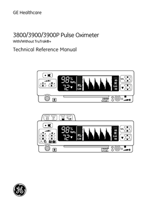
3800/3900/3900P Pulse Oximeter With/Without TruTrak®+
Technical Reference Manual
♥
GE Healthcare
3800/3900/3900P Pulse Oximeter With/Without TruTrak®+
Technical Reference Manual
♥
6050-0006-404 March 2005
Important Rx Only (USA) Attention! Consult the accompanying instructions, including all safety precautions, before using or servicing this device.
Responsibility of the manufacturer The safety, reliability, and performance of this device can be assured only under the following conditions: •
Fittings, extensions, readjustments, changes, or repairs are carried out by authorized personnel.
•
The electrical installation complies with relevant standards and regulations.
•
The device is used according to the accompanying operating instructions and is serviced and maintained in accordance with this manual.
Service and repair Service and repair procedures must be performed by authorized service personnel. Repair this device or its parts only in accordance with instructions provided by the manufacturer. To order replacement parts or for assistance, contact an authorized service office. When shipping the monitor for repair, clean the monitor, allow it to dry completely, and pack it for shipment in the original shipping container, if possible.
Trademarks Datex®, Ohmeda®, OxyTip®, TruTrak®, PerfTrak®, TeleOximetry®, and PIr™ are the property of GE Healthcare Finland Oy. All other product and company names are the property of their respective owners.
0537
GE Healthcare Finland Oy Helsinki, Finland +358 10 394 11 www.gehealthcare.com © 2005 General Electric Company. All rights reserved.
Contents 1/Overview Related information...1-1 Technical competence...1-1 1.1
General description...1-2 1.1.1 Major components, block interconnect diagram...1-2 1.1.2 General subassembly description...1-2 Power inlet module...1-2 Power supply...1-3 Battery...1-3 System board...1-3 Oximetry board...1-3 Sensor filter board...1-3 Front panel...1-3 3900P printer ...1-3
1.2
Compliance with standards ...1-4 1.2.1 General safety requirements...1-4 Safety checks for software...1-4 1.2.2 Electromagnetic compatibility (EMC)...1-5 Electromagnetic effects ...1-8
1.3
Specifications...1-9 1.3.1 General...1-9 Circuitry...1-9 Displays ...1-9 Audio indicators...1-9 Dimensions and weight...1-9 1.3.2 Factory settings... 1-10 Mode switches... 1-10 1.3.3 Measurement... 1-11 SpO2 ... 1-11 Pulse rate ... 1-11 PI r pulsatile value... 1-11 Interfering substances ...1-11 Sensor emitter wavelength ranges...1-11 1.3.4 Alarms... 1-12 Audible alarms... 1-12 Alarm limits ... 1-12 1.3.5 Environmental... 1-12 1.3.6 Electrical... 1-12 Power... 1-12 Current leakage...1-12 Fuse... 1-12 Battery... 1-13 1.3.7 RS-232 connector... 1-13
1.4
Precautions ...1-14 1.4.1 Warnings... 1-14 1.4.2 Cautions... 1-15
1.5
Safety guidelines...1-16 1.5.1 Cleaning... 1-16
i
Contents 2/Theory of Operations
ii
2.1
Power supply and power inlet module...2-1
2.2
System board ...2-2 System board functions...2-2 2.2.1 System board data management...2-2 Microprocessor ...2-3 SRAM...2-3 Flash memory and software upgrade socket...2-3 RS-232 connector interface ...2-3 Mode switch...2-3 Alarm signal and pulse tone generator...2-3 Microprocessor supervisor ...2-3 Audio amplifier ...2-4 Front panel interface...2-4 Background debug ...2-4 (3900/3900P) Real-time clock...2-4 (3900P) Printer interface ...2-4 2.2.2 System board power management ...2-4 + 5 V supply...2-4 Battery charger...2-5 Battery monitor...2-5 AC monitor...2-5 + VR supply...2-5 Power on/standby circuitry...2-5
2.3
Switch board...2-6
2.4
Oximetry board...2-7 2.4.1 Oximetry board power supply section...2-7 2.4.2 Oximetry board digital section...2-7 Microprocessor ...2-7 Flash memory...2-7 SRAM...2-7 DAC ...2-7 Reset circuit...2-7 2.4.3 Oximetry board analog section...2-8 Detector preamplifier...2-8 Interference detect...2-9 Multiplexed low-pass filter...2-9 Test circuit...2-9 Ambient light subtraction ...2-9 Composite gain stage ...2-9 Demultiplex and low-pass filter...2-9 High-pass filter and multiplex...2-9 AC gain stage...2-9 Demultiplex low pass ...2-9 Analog multiplexor and buffer...2-10 Multiplexor... 2-10 LED drive... 2-11 Sensor monitor... 2-11 Sensor identification ... 2-11
2.5
Passive filtering (sensor filter board or flex cable)...2-11
2.6
3900P Printer interface...2-12
Contents 2.6.1 Printer board... 2-12 Motor driver... 2-12 Tachometer shaper...2-12 Head drivers... 2-12 ESD protection... 2-12 Temperature sensor/keypad decoder ...2-13 2.6.2 Printer button board...2-13
3/Test and Upgrade Procedures 3.1
Functionality test ...3-1 3.1.1 Printer test (3900P)...3-3 3.1.2 Diagnostic self-test...3-4
3.2
Electrical safety check ...3-4
3.3
Software upgrade...3-5 3.3.1 Remove the cover and identify the system board...3-6 3.3.2 (Optional) Check the installed software versions...3-6 3.3.3 System software upgrade using the U-LOADER or LOADER chip...3-7 3.3.4 System software upgrade using the SYS chip...3-9 3.3.5 Oximetry software upgrade (monitors without TruTrak+)...3-11 3.3.6 Install the cover and check the installation...3-12
4/Troubleshooting 4.1
Messages...4-1
4.2
System failure error codes...4-5 4.2.1 Nonfatal errors-the system continues running ...4-5 4.2.2 Fatal errors-the system sounds an alarm tone and halts ...4-6
4.3
Troubleshooting guide...4-8
4.4
3900/3900P TeleOximetry messages and troubleshooting...4-12 4.4.1 TeleOximetry status messages...4-12 4.4.2 TeleOximetry troubleshooting guide... 4-14
4.5
Test points...4-15 4.5.1 System board test points...4-15 4.5.2 Oximetry board test points ...4-16 Oximetry board in TruTrak+ monitors ...4-16 Oximetry board in monitors without TruTrak+...4-17
5/Repair and Replacement Procedures 5.1
Oximeter cover...5-2 5.1.1 Removing the cover...5-2 5.1.2 Replacing the cover...5-2
5.2
Front panel assembly...5-3 5.2.1 Front panel, remove and disassemble ...5-3 5.2.2 Sensor filter replacement (board or flex cable)...5-4 Sensor filter board...5-4 Sensor filter flex cable...5-4 5.2.3 Sensor connector replacement...5-4 5.2.4 Switch board LCD replacement...5-4 5.2.5 Button pad replacement...5-4 iii
Contents 5.2.6 Switch board replacement ...5-5 5.2.7 Front panel, reassemble and reinstall...5-5 5.3
Power-related components...5-7 5.3.1 Power supply replacement...5-7 5.3.2 Equipotential ground connector replacement...5-7 5.3.3 Power inlet module replacement...5-8 5.3.4 Fuse replacement ...5-9 5.3.5 Battery replacement...5-10
5.4
Speaker replacement ...5-11
5.5
System board replacement ...5-12
5.6
Oximetry board replacement...5-14
5.7
3900P Printer repair...5-15 5.7.1 Printer board replacement...5-15 5.7.2 Printer button board replacement...5-15
6/Illustrated Parts
iv
6.1
Service kits...6-2
6.2
Front panel assembly...6-6 6.2.1 Front panel components ...6-6 6.2.2 Front panel assembly drawing (3800)...6-7 6.2.3 Front panel assembly drawing (3900/3900P)...6-8
6.3
Chassis assembly...6-9 6.3.1 Chassis components...6-9 6.3.2 Chassis assembly drawing ...6-10
6.4
Printer/cover assembly (3900P)...6-11 6.4.1 Printer/cover components... 6-11 6.4.2 Printer/cover assembly drawing...6-12
6.5
System board ...6-13 6.5.1 System board components shown... 6-13 6.5.2 System board layout (all monitors except 3800 without TruTrak+) ... 6-13 6.5.3 System board layout (3800 REF 6051-0000-064 and 6051-0000-163)...6-14
6.6
Oximetry board...6-15 6.6.1 Oximetry board layout (TruTrak+ monitors)...6-15 6.6.2 Oximetry board layout (monitors without TruTrak+)...6-16
6.7
Switch board...6-17
6.8
Sensor filter flex cable (TruTrak+ monitors)...6-18
6.9
Sensor filter board (monitors without TruTrak+)...6-18
6.9
3900P Printer boards ...6-19 6.9.1 3900P Printer board...6-19 6.9.2 3900P Printer button board...6-19
1/Overview This manual provides instructions for servicing all Model 3800, Model 3900, and Model 3900P pulse oximeters. This includes models with TruTrak®+ technology, the patented technology for enhanced performance during conditions of clinical patient motion. Important: Only OxyTip®+ sensors can be used with TruTrak+ monitors. The 3900P is identical to the 3900, except that it contains an integral printer. All references to printer functions and components are for the 3900P only. This chapter contains: •
A general description of the oximeter and its main components.
•
Oximeter specifications.
•
Precautions, including specific warnings and cautions you must follow when servicing the oximeter.
•
Safety procedures you must follow when handling or repairing equipment that may be contaminated.
Related information For a detailed description of your monitor’s components, functions, general operating guidelines, and RS-232 interface, see the 3900/3900P Pulse Oximeter User’s Manual or the 3800 Pulse Oximeter User’s Manual. If you need to reference printed circuit board schematics and component lists, purchase and refer to the information contained in the 3800/3900/3900P PCA Drawings Service Kit. See chapter 6 for a description and order number. For information related to sensors (sensor application and cleaning, for example), refer to the instructions for the sensor.
Technical competence CAUTION: Only qualified service personnel should perform the procedures described in this manual. Only trained service personnel or competent individuals who are experienced with servicing medical devices of this nature should perform the procedures described in this service manual.
1-1
3800/3900/3900P Technical Reference Manual
1.1 General description The 3800, 3900, and 3900P pulse oximeters are noninvasive, arterial oxygen saturation and pulse rate monitors. Through the use of a sensor applied to the patient and connected to the monitor, these pulse oximeters measure the absorption of selected wavelengths of light to calculate pulse rate and arterial oxygen saturation. The light generated in the sensor passes through the tissue and is converted into an electronic signal by a photodetector in the sensor. The electronic signal passes to the oximeter and is amplified. Analog and digital signal processing convert the light intensity information into SpO2 and pulse rate values. Both models feature two easy-to-read displays that present patient data and status information. •
The numeric LEDs (light-emitting diodes) show the SpO2 and pulse rate values.
•
The LCD (liquid crystal display) shows alarm messages, the plethysmographic waveform (or data), and the high and low SpO 2 and pulse rate limit settings. This display also shows the Relative Perfusion Index (PIr®) pulsatile value and menus as appropriate for the monitor.
1.1.1 Major components, block interconnect diagram AC Power
Power inlet module
Power supply +12 V
3900P Printer board
Front panel
Mode switches
RS-232 port
3900P Printer button board
System board
Oximetry board
Sensor filter board
Oximetry sensor
Battery
1.1.2 General subassembly description The descriptions that follow discuss the interaction of major components within the pulse oximeter. More detailed information for each component is found in chapter 2.
Power inlet module The primary function of the power inlet module is to allow the oximeter to be connected to an AC power source. It also serves as a filter for electromagnetic compatibility (EMC) compliance and contains fuses to limit the current flow. This module is connected to the power supply.
1-2
1/Overview
Power supply The power supply converts power from any AC source between 90 and 264 VAC at 47 to 63 Hz to +12 VDC. It also provides the necessary isolation between the patient and the mains. The +12 VDC is connected to the system board for further conditioning.
Battery Power for the unit, when it is not connected to the AC mains power, is supplied by the battery. The nominal battery voltage is 8 V. The battery is connected to the system board, which conditions the battery and charges the battery when the unit is connected to the AC mains power.
System board This board conditions power from the +12 V power supply and the battery. It charges the battery when supplied with a DC voltage from the power supply. On power up it reads the position of the mode switches on the back panel. It communicates through the RS-232 port. The board sends data to the front panel for display and monitors the button switches. An upgrade socket on the board provides a means of upgrading the software. The board monitors and sends commands to the oximetry board via a serial interface and a few discrete digital lines. The board communicates printer functions to the 3900P printer board. It also contains a real-time clock for use in 3900/3900P monitors.
Oximetry board This board drives the LEDs in the oximetry sensor and receives the photodetector signals. The signals pass through the sensor filter board. The photodetector signal is conditioned and processed on the oximetry board and the output is used to determine patient oxygen saturation, perfusion, and pulse rate. The output is sent to the system board.
Sensor filter board This board filters out unwanted electrical signals (EMC, surges, noise, etc.). These are internal signals that should not leave the unit and external signals that should not enter the unit.
Front panel This panel displays information sent to it by the system board: saturation, pulse rate, plethysmographic waveform, alarm messages, and alarm indicators. The panel also contains the primary user-interface switches. It displays the AC power status and contains the power/standby switch.
3900P printer The printer board and printer button board interface to the system board. The system board controls the 3900P printer to provide printed output of current monitoring data, stored trend, and summary data.
1-3
3800/3900/3900P Technical Reference Manual
1.2 Compliance with standards Compliance with standards The presence on the monitor of any symbol described below indicates compliance with the standard represented by that symbol. Medical Device Directive 93/42/EEC of the European Union for a class I (with a measuring function), IIa, IIb, or III device. 0537
Medical electrical equipment classified in the US and Canada with respect to electric shock, fire, and mechanical hazards only, in accordance with the Canadian Standards Association CAN/CSA C22.2 No. 601.1 and Underwriters Laboratories Inc. UL 2601-1. Medical electrical equipment classified with respect to electric shock, fire, and mechanical hazards only, in accordance with the Canadian Standards Association CAN/CSA C22.2 No. 601.1. Medical electrical equipment classified with respect to electric shock, fire, and mechanical hazards only, in accordance with Underwriters Laboratories Inc. UL 2601-1.
1.2.1 General safety requirements The 3800, 3900, and 3900P pulse oximeters comply with the requirements of EN 606011 Part 1: General requirements for safety of medical electrical equipment. Type BF applied part. Type of protection against electric shock: Class I/Internal electrical power source Degree of protection against ingress of liquids: Ordinary (IPX0) Mode of operation: Continuous The oximeter also complies with the following: EN 865
Pulse oximeters – Particular requirements
EN 475
Medical devices – Electrically-generated alarm signals.
Safety checks for software Software design controls include performance of a risk analysis using methods consistent with EN 1441 Medical devices – Risk analysis. To ensure proper operation of the software, the monitor employs three separate watchdog circuits for the microprocessors, power-on self-tests (including memory checksum and calibration verification), and memory tests during monitoring. The software continuously monitors the patient sensor and, if a failure is detected, discontinues power to the sensor.
1-4
1/Overview
1.2.2 Electromagnetic compatibility (EMC) The 3800, 3900, and 3900P pulse oximeters comply with the requirements of EN 606011-2: Electromagnetic compatibility - Requirements and tests. Emissions
EN 55011 Group I, Class B
The 3800, 3900, and 3900P oximeters were tested with no peripheral devices when operating on battery power. The 3800 pulse oximeter was tested with an RS-232 cable attached when operating on AC power. The 3900 and 3900P pulse oximeters were tested with an RS-232 cable and analog output cables attached when operating on AC power. A USRobotics Sportster Fax Modem was connected to the 3900 when Electrical Safety and EMC testing was performed. The analog output was measured using a fiber optic link during testing. When installing and using this monitor, take precautions to ensure electromagnetic compatibility. Table 1-1. Guidance and manufacturer’s declaration - electromagnetic emissions The 3800/3900/3900P TruTrak+ is suitable for use in the electromagnetic environment specified below. The customer or the user of the 3800/3900/3900P TruTrak+ should assure that it is used in such an environment. Emissions test RF emissions CISPR 11 RF emissions CISPR 11 Harmonic emissions IEC 61000-3-2 Voltage fluctuations/flicker emissions IEC 61000-3-3
Compliance
Electromagnetic environment - guidance
Group 1
The 3800/3900/3900P TruTrak+ uses RF energy only for its internal function. Therefore, its RF emissions are very low and are not likely to cause any interference in nearby electronic equipment.
Class B
Class A
The 3800/3900/3900P TruTrak+ is suitable for use in all establishments, including domestic establishments and those directly connected to the public low-voltage power supply network that supplies buildings used for domestic purposes.
Complies
1-5
3800/3900/3900P Technical Reference Manual
Table 1-2 Guidance and manufacturer’s declaration - electromagnetic immunity The 3800/3900/3900P TruTrak+ is intended for use in the electromagnetic environment specified below. The customer or the user of the 3800/3900/3900P TruTrak+ should assure that it is used in such an environment: Immunity test
IEC 60601-1-2 test level
Compliance level
Electrostatic discharge (ESD)
± 6 kV contact
± 6 kV contact
± 8 kV air
± 8 kV air
± 2 kV for power supply lines
± 2 kV for power supply lines
± 1 kV for input/output lines
± 1 kV for input/output lines
Surge
± 1 kV differential mode
± 1 kV differential mode
IEC 61000-4-5
± 2 kV common mode
± 2 kV common mode
Voltage dips, short interruptions and vol tage variations on power supply input lines
< 5 % UT
< 5 % UT
(> 95 % dip in U T) for 0,5 cycle
(> 95 % dip in U T) for 0,5 cycle
40 % UT
40 % UT
(60 % dip in UT) for 5 cycles
(60 % dip in UT) for 5 cycles
70 % UT
70 % UT
(30 % dip in UT) for 25 cycles
(30 % dip in UT) for 25 cycles
IEC 61000-4-2
Electrical fast transient/burst IEC 61000-4-4
IEC 61000-4-11
Power fre quency (50/60 Hz) magnetic field
< 5 % UT
< 5 % UT
(> 95 % dip in U T) for 5 sec
(> 95 % dip in U T) for 5 sec
3 A/m
3 A/m
IEC 61000-4-8 NOTE: U T is the a.c. mains voltage prior to application of the test level.
1-6
Electromagnetic environment guidance Floors should be wood, concrete, or ceramic tile. If floors are covered with synthetic material, the relative humi dity should be at least 30%. Mains power quality should be that of a typical commercial or hospital env i ronment Mains power quality should be that of a typical commercial or hospital env i ronment. Mains power quality should be that of a typical commercial or hospital env i ronment. If the user of the 3800/3900/3900P TruTrak+ requires continued operation during power mains interruptions, it is recommended that the 3800/3900/3900P TruTrak+ be powered from an uninterrupt i ble power supply or a battery. Power frequency magnetic fields should be at levels characteristic of a typ i cal location in a typical commercial or hospital environment.
1/Overview
Table 1-3 Guidance and manufacturer’s declaration - electromagnetic Immunity The 3800/3900/3900P TruTrak+ is intended for use in the electromagnetic environment specified below. The customer or the user of the 3800/3900/3900P TruTrak+ should assure that it is used in such an environment: Immunity test
IEC 60601 test level
Compliance level
Electromagnetic environment - guidance
P ortable and mobile RF communications equipment should be used no closer to any part of the 3800/3900/3900P TruTrak+, inclu ding cables, than the recommended separation distance calculated from the equation applicable for the frequency of the transmitter. Recommended Separation Distance Conducted RF IEC 61000-4-6
3 Vrms 150 kHz to 80 MHz
Radiated RF IEC 61000-4-3
3 V/m 80 MHz to 2,5 GHz
d = 0.70 P 5V
5 V/m
d = 0.70 P
80 MHz to 800 MHz
d = 1.40 P
800 MHz to 2,5 GHz
where P is the maximum output power rat ing of the transmitter in watts (W) according to the trans mitter manufacturer and d is the recommended separation dis tance in meters (m). Field strengths from fixed RF transmitters, as determined by an electromagnetic site survey, a should be less than the compliance level in each fre quency range.b Interference may occur in the vicinity of equipment marked with the following symbol:
NOTE 1:
At 80 MHz and 800 MHz, the separation distance for the higher frequency range applies.
NOTE 2:
These guidelines may not apply in all situations. Ele ctromagnetic propagation is affected by absorption and reflection from structures, objects, and people.
a
Field strengths from fixed transmitters, such as base stations for radio (cellular/cordless) telephones and land mobile radios, amateur radio, AM and FM radio broadcast, and TV broadcast cannot be predicted theoreti cally with accuracy. To assess the electromagnetic environment due to fixed RF trans mitters, an electromagnetic site survey should be considered. If the measured field strength in the location in which the 3800/3900/3900P TruTrak+ is used exceeds the applicable RF compliance level above, the 3800/3900/3900P TruTrak+ should be observed to verify normal operation. If abnormal performance is observed, additional measures may be necessary, such as reorienting or relocating the 3800/3900/3900P TruTrak+.
b
Over the frequency range 150 kHz to 80 MHz, field strengths should be less than 5 V/m.
1-7
3800/3900/3900P Technical Reference Manual
Electromagnetic effects Electromagnetic interference, including interference from portable and mobile radio frequency (RF) communications equipment, can affect this monitor. Table 1-4 Recommended Separation Distances between Portable and Mobile RF Communications Equipment and the 3800/3900/3900P TruTrak+ The 3800/3900/3900P TruTrak+ is intended for use in an electromagnetic environment in which RF disturbances are controlled. The customer or the user of the 3800/3900/3900P TruTrak+ can prevent electromagnetic interference by maintaining a minimum distance between portable and mobile RF communications equipment (transmitters) and the 3800/3900/3900P TruTrak+ as recommended below, according to the maximum output power of the communications equipment. Separation distance according to the frequency of the transmitter Rated maximum output power of transmitter
m 150 kHz to 80 MHz
80 MHz to 800 MHz
800 MHz to 2,5 GHz
d = 0.70 P
d = 0.70 P
d = 1.40 P
0.01
0.07
0.07
0.14
0.1
0.22
0.22
0.44
1
0.70
0.70
1.40
10
2.2
2.2
4.4
100
7.0
7.0
14.0
W
For transmitters rated at a maximum output power not listed above, the recommended separation distance d in meters (m) can be estimated using the equation applicable to the frequency of the transmitter, where P is the maximum output power rating of the transmitter in watts (W) according to the transmitter manufacturer. NOTE 1:
At 80 MHz and 800 MHz, the separation distance for the higher frequency range applies.
NOTE 2:
These guidelines may not apply in all situations. Electromagnetic propagation is affected by absorption and reflection from structures, objects, and people.
Indications that the monitor is experiencing electromagnetic interference include the following: •
Variations in the PerfTrak waveform display.
•
Sudden increases or decreases in the waveform height that do not correlate to the physiological condition of the patient.
•
Sensor-related messages that are not resolved by the instructions found in this manual.
•
The display of dashes on numeric LEDs when a valid physiological signal is present.
•
(3900P) Printed output that is garbled, solid black, or missing.
This interference may be intermittent and careful correlation between the effect and its possible source is important. Indications of interference should not occur if the monitor is used within its intended electromagnetic environment.
1-8
1/Overview
1.3 Specifications Unless otherwise indicated, all specifications are nominal and are subject to change without notice.
1.3.1 General Circuitry Microprocessor-controlled Automatic self-test of oximeter when powered on Automatic setting of default parameters Automatic alarm messages (3800) Up to 12 hours of stored trend data output through the RS-232 serial port for SpO2 , pulse rate, and alarm messages (3900/3900P) Real-time data output or up to 24 hours of stored trend data output through the RS-232 port for SpO 2, pulse rate, PI r pulsatile value, and alarm messages; SpO2 and pulse rate output through two analog channels
Displays The displayed SpO 2, pulse rate, and PIr values are updated every second. The plethysmographic waveform sweep is updated every 4 seconds.
Numeric display (Light Emitting Diodes-LEDs) Arterial oxygen saturation (SpO 2) reading Pulse rate reading
Graphic display (Liquid Crystal Display-LCD) Plethysmographic waveform High and low SpO2 and pulse rate alarm limits settings Sensor condition alarms Messages-alarm messages and system operational status messages Contrast adjustment (All monitors except 3800 without TruTrak+) PI r pulsatile value (3900/3900P) SpO2 real-time or stored data graph (3900/3900P) PI r pulsatile value real-time or stored data graph
Audio indicators Adjustable-volume pulse beep; pitch modulation reflects changing SpO2 levels Adjustable-volume alarm tone Alarm silence (120 seconds); all mute (continuous silence) Out-of-limits alarms for SpO 2 and pulse rate Sensor-condition, system-failure, and recharge-battery alarms
Dimensions and weight (3800/3900) height x width x depth: 9.4 cm (3.7 in) x 24.4 cm (9.5 in) x 22.5 cm (8.9 in) (3900P) height x width x depth: 10.4 cm (4.1 in) x 24.4 cm (9.5 in) x 22.5 cm (8.9 in) Weight: 3800/3900-2.9 kg (6.5 lbs); 3900P-3.2 kg (7.0 lbs)
1-9
3800/3900/3900P Technical Reference Manual
1.3.2 Factory settings Parameter
3900/3900P
3800
High SpO2 limit
OFF (appears as – – –)
OFF (appears as – – –)
Low SpO2 limit
85%
85%
High pulse rate
130 bpm
Adult mode: 130 bpm Neonate mode: 200 bpm
Low pulse rate
40 bpm
Adult mode: 40 bpm Neonate mode: 100 bpm
Alarm volume
3
3
Pulse volume
2
2
Save limits
No
Not applicable
Data output mode (printer and modem)
SpO2
Not applicable
Data output resolution
6-second
Not applicable
All mute
Yes
Not applicable
Serial transmission baud rate
9600
Not applicable
Analog
0.0 V
Not applicable
Print contrast
5
Not applicable
Date format
DD/MM/YY
Not applicable
Time format
HH MM
Not applicable
Switch
3900/3900P options
3800 options
Language
Danish, Dutch, English (factory setting), Finnish, French, German, Italian, Japanese, Norwegian, Portuguese, Polish, Spanish, and Swedish
English (factory setting), French, German, Italian, Japanese, Portuguese, Spanish, and Swedish
Averaging mode
Long / TruTrak+ (12 sec. factory setting), Medium (6 sec.), and Short (3 sec.)
Long / TruTrak+ (12 sec. factory setting), Medium (6 sec.), and Short (3 sec.)
Patient mode
Not applicable
Adult (factory setting) and Neonate
(TruTrak + monitors) PI r pulsatile value display
Yes (factory setting) and No
Yes (factory setting) and No
(Monitors without TruTrak +) Fractional (factory setting) SpO2 calibration and functional
Fractional (factory setting) and functional
EMI line frequency
60 Hz
Mode switches
1-10
60 Hz
1/Overview
1.3.3 Measurement SpO 2
TruTrak + monitors
Monitors without TruTrak +
Calibration
Functional
Fractional or Functional
Range
0 to 100%
0 to 100%
Accuracy, Arms (previously represented by 1 SD)
70 to 100% ± 2 digits 70 to 100% ± 3 digits during conditions of clinical patient motion (with TruTrak + enabled) Below 70% unspecified
Accuracy, 1 SD
80 to 100% ± 2% 60 to 79% ± 3% Below 60% unspecified
Resolution
Pulse rate Range Accuracy (assuming a constant pulse rate) Resolution
1%
1%
TruTrak + monitors
Monitors without TruTrak +
30 to 250 bpm ± 2% or ± 2 bpm (whichever is greater)
20 to 255 bpm 40 to 235 bpm ± 1.7% of reading
Accuracy during conditions of clinical patient motion: unspecified 1 bpm TruTrak + monitors and 3900/3900P without TruTrak +
PIr pulsatile value
1 bpm
3800 without TruTrak+
Range
0.00 to 9.99
Not applicable
Averaging interval
12 seconds
Not applicable
Resolution
0.01
Not applicable
Interfering substances Carboxyhemoglobin may erroneously increase readings. The level of increase is approximately equal to the amount of carboxyhemoglobin present. Dyes, or any substances containing dyes, that change usual arterial pigmentation may cause erroneous readings.
Sensor emitter wavelength ranges Red LED peak wavelength range: 650 to 670 nm Infrared (IR) LED peak wavelength range: 930 to 950 nm Average power: ≤ 1 mW
1-11
3800/3900/3900P Technical Reference Manual
1.3.4 Alarms Audible alarms Setting levels available: Alarm: 1 through 5 Pulse beep: OFF and 1 through 5 Volume intensity at 1-meter distance: Setting of 1: 45 decibels (minimum) Setting of 5: 85 decibels (maximum)
Alarm limits SpO2 alarm limit range: High = 50 to 100%, or OFF Low = OFF, or 50 to 100% Pulse rate alarm limit range in beats per minute (bpm): TruTrak + monitors
Monitors without TruTrak +
High = 30 to 235, or OFF Low = OFF, or 30 to 235
High = 40 to 235, or OFF Low = OFF, or 40 to 235
1.3.5 Environmental Parameter
Operating
Transport and Storage
Temperature
0 to 50 ºC (32 to 122 ºF)
–40 to 70 ºC (–40 to 158 ºF) 3900P with printer paper: –20 to 45 °C (4 to 113 °F)
Relative humidity, noncondensing
20% to 95%
5% to 95%
Pressure
1060 to 697 hPa
1060 to 188 hPa
Approximate elevation
–378 to 3048 m (–1240 to 10,000 ft.)
–378 to 12.2 km (–1240 to 40,000 ft.)
1.3.6 Electrical Power Consumption (typical): 15 watts (3900P-20 watts) Input voltage range: 90 to 264 VAC at 47-63 Hz Current (typical): 0.45 Arms at 100 V, 0.37 Arms at 120 V, 0.25 Arms at 220/230/240 V
Current leakage With power on, forward or reverse polarity: 100 microamperes maximum Ground resistance: less than 0.1 Ω
Fuse T2.0AH/250V, 5mm (OD) x 20 mm (Length)
1-12
1/Overview
Battery Type: 8 volt, sealed lead-acid Capacity: 3.2 ampere hours Operation time for a new battery at normal operating temperatures: At least 5 1/2 hours (with all functions operative from a fully charged battery). 3900P-approximately 4 hours when printing. Low battery indicator (LOW BATTERY): indicates the remaining battery capacity is between 5 and 15 minutes. Important: To prevent permanent damage to the battery, recharge a discharged battery within eight hours after LOW BATTERY is displayed. Charge time: 4 hours = 80% capacity 8 hours = 100% capacity Life: several hundred charge/discharge cycles Shelf life: 6 months (maximum if not recharged) when stored at room temperature; batteries stored for extended periods of time should be recharged every six months to maintain the charging capacity.
1.3.7 RS-232 connector Connector type: 9-pin standard D, female 3900/3900P-pins 1 and 4 are not used. 3800-pins 1, 4, 6 and 9 are not used.
Serial output RS 232
1
2 = oximeter receives data 3 = oximeter transmits data 5 = signal ground 7 = RTS (Request To Send) 8 = CTS (Clear To Send)
Data output every 2 seconds (auto-output mode) or 6 seconds (trend-output mode): •
(All monitors) SpO2 , pulse rate, alarm limit violation messages, and displayed alarm messages
•
(3900/3900P) Relative Perfusion Index, time stamp, and custom patient label
Baud rate: 3800-9600 baud; 3900/3900P-9600, 19.2 K, 38.4 K, or 57.6 K baud Full duplex; no parity 8 bits per character; 1 start bit; 1 stop bit Handshaking: CTS/RTS
(3900/3900P) Analog output RS 232
1
5 = signal ground 6 = SpO2 (0 to 1 Vdc ± 20 mV = 0 to 100% ± 2.0%) 9 = Pulse rate (0 to 1 Vdc ± 20 mV = 0 to 255 bpm ± 2.0%)
1-13